Table of Contents
Advertisement
Quick Links
Advertisement
Table of Contents

Related Manuals for Sony DVP-K800D


Summary of Contents for Sony DVP-K800D
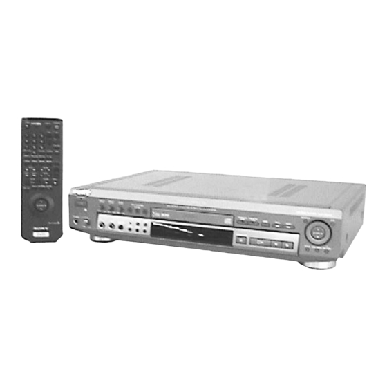
- Page 1 DVP-K800D RMT-D106E SERVICE MANUAL Chinese Model E Model Hong kong Model Spanish Model Taiwan Model • Refer to the OPERATION MANUAL (9-921-669-21) and DVD MECHANISM OPERATION MANUAL (9-921-669-31) for DVD mechanism. SPECIFICATIONS CD/DVD PLAYER MICROFILM...
- Page 2 COMPONENTS IDENTIFIED BY MARK ! OR DOTTED LINE WITH MARK ! ON THE SCHEMATIC DIAGRAMS AND IN THE PARTS LIST ARE CRITICAL TO SAFE OPERATION. REPLACE THESE COMPONENTS WITH SONY PARTS WHOSE PART NUMBERS APPEAR AS SHOWN IN THIS MANUAL OR IN SUPPLEMENTS PUBLISHED BY SONY.
-
Page 3: Table Of Contents
Users are expected to take of the followings by thermselves SCHEMATIC DIAGRAMS --- “C” code ..................8 5-2. Consult Sony Service --- “E” code, E : YY: ZZ ......8 4-1. FRAME SCHEMATIC DIAGRAM ........... 4-1 4-2. PRINTED WIRING BOARDS AND GENERAL SCHEMATIC DIAGRAMS ............ - Page 4 TEST MODE 5-1. How to Enter Test Mode ............. 5-1 5-2. System Control Diagnosis ............5-1 5-2-1. Selection of Check Items ............5-2 5-2-1-1. Testing the Selected Item ............5-2 5-2-1-2. Testing All Items ............... 5-3 5-2-2. Error Display ................5-3 5-2-3.
-
Page 5: Service Note
DVP-K800D SERVICE NOTE DISK REMOVAL PROCEDURE (at POWER OFF) Insert a cross-tip screwdriver into a hole at the bottom, and rotate the cam gear 1 in direction A. (See Fig. 1) Note: To prevent a damage of cam gear, rotate it in direction A by 1/4 turn. -
Page 6: Replacing Optical Pick-Up
REPLACING OPTICAL PICK-UP 3-1. Handling 1) A red laser diode for DVD requires more attention to static 3) In handling the KHS-180A (RP), do not touch inhibited parts electricity than general infrared laser diodes for CD. shown in Fig. 5, but grip the slide base bearing and U-shaped guide. -
Page 7: Note On Assembling Mechanical Deck
NOTE ON ASSEMBLING MECHANICAL DECK 4-1. Application of Grease Grease must be applied if the following parts are replaced. (See Fig. 6) Note 1: Recommended grease is Foil KG-70MP. Note 2: In applying grease, take care not to allow grease to stick to other parts (particularly, rubber belt, spindle motor, and optical pick-up). Base unit holder Skew cam 2 bosses... -
Page 8: Cleaning Spindle Motor Turntable
4-2. Cleaning Spindle Motor Turntable 4-4. Deformation of Insulator 1) Remove the tray. (Refer to 2-2) 1) Assemble the spindle base into the base unit. 2) Clean the spindle motor turntable if disc antiskid rubber (black) 2) Lock with 4 shoulder screws. (See Fig. 9) is dirty. -
Page 9: Note On Mounting Fg-43 Board
Jitter/Gain TOC/Control Data Read Others Spin Down Seek Error Recovery 5-2. Consult Sony Service – – – “E” code, Fig. 11 E : YY : ZZ 4-7. Note on Mounting TK-47 Board Refer to the item “5-8. Appendix” for details. - Page 10 CLV servo does not lock in within the specified time. UNKONWN FG servo does not reach the target speed within the NO DISC specified time. CD 12 cm Spindle is not rotating at x1 speed. (RF Edge) CD 8 cm System control requests address that does not exist.
-
Page 11: General
DVP-K800D SECTION 1 This section is extracted from GENERAL instruction manual. - Page 20 1-10...
- Page 21 1-11...
- Page 22 1-12...
- Page 23 1-13E...
-
Page 24: Disassembly
DVP-K800D SECTION 2 DISASSEMBLY NOTE: Follow the disassembly procedure in the numerical order given. 2-1. UPPER CASE 1 Tapping screws 1 Tapping screws Case Case 2 Vertically up Front panel 1 Tapping screws 2-2. FRONT PANEL BLOCK ASSEMBLY CN205 5 Screw +BVTP3 ×... -
Page 25: Board
2-3. AU-217 BOARD AU-217 board 3 Screws +BVTP 3 × 8 1 Connector (From CN205) 2 Screws +BVTP 3 × 10 1 Flat cable (From CN204) 5 Flat cables (From CN201and CN203) 2-4. MB-78 BOARD 2 Screws +BVTP 3 × 8 3 Cover (upper) 1 Connectors From CN001... -
Page 26: Power Block
2-5. KR-35 BOARD 1 Flat cable (From CN503) 1 Connector 3 Screws +BVTP 3 × 8 (From CN501) 1 Flat cable (From CN502) KR-35 board 2 Screw +BVTP 3 × 10 2-6. POWER BLOCK 2 Screws +WHD B3 1 Connector (From CN201) 1 Connector (From CN101) -
Page 27: Board, Mc-115/Vr-68 Board Block
2-7. TK-47 BOARD 1 Screws +BVTP 3 × 8 2 Chassis bracket (B) 3 Screws +BVTP 3 × 8 3 Screws +BVTP 3 × 8 Mechanism deck 4 Flexible board (From CN001) TK-47 board 4 Flexible board (From CN002) 4 Connector (From CN004) 5 Screws +BVTP 3 ×... -
Page 28: Circuit Boards Location
2-9. CIRCUIT BOARDS LOCATION Power Block VR-68 AU-217 MIC/ECHO AUDIO D/A CONVERTER, LEVEL LINE OUT HP-116 FG-43 PHONES (SLED MOTOR) JACK FR-156 POWER SWITCH MC-115 MIC 1, 2 JACKS KR-35 KARAOKE MB-78 DSP/ VIDEO, SERVO/SYSTEM MIC 3, 4 JACKS CONTROL, AUDIO TK-47 (RF, SERVO) FL-106... -
Page 29: Block Diagrams
DVP-K800D SECTION 3 BLOCK DIAGRAMS 3-1. OVERALL BLOCK DIAGRAM TK-47 BOARD MB-78 BOARD AU-217 BOARD IC352 IC208 OPTICAL PICK-UP DVD RF SPD IF OPTICAL BLOCK DIGITAL IC503 KHS-180A/JIN IC011 CD DATA CD DATA SPDIF AC3 IC806 CD BCK CD BCK... -
Page 30: Rf/Servo Block Diagram
DVP-K800D 3-2. RF/SERVO BLOCK DIAGRAM CN451 1 CD 0.5 V/div 0.2 µsec/div MB-78 BOARD CN303 CN451 3 DVD TK- 47 BOARD CHECK Q010 IC004 CN451 JIT PWM OPTICAL PICK-UP BUFFER CD RF 0.5 V/div 0.1 µsec/div FOR CHECK BLOCK IC006... - Page 31 DVP-K800D 3-3. VIDEO/AUDIO BLOCK DIAGRAM MB-78 BOARD AU-217 BOARD Q353 BUFFER IC208 IC352 CN252 CN201 IC804 158 DOUT CTL SPDIF OPTICAL IC203 DIGITAL OUT MPEG2 A/V IC252 DOLBY DIGITAL COAXIAL DECODER VIDEO ENCODER IC252 ^¢ DVD IC807 IC251 IC351 J354 TO/FROM 41 38 .
-
Page 32: Audio Block Diagram
DVP-K800D 3-4. AUDIO BLOCK DIAGRAM AU-217 BOARD J354 KR-35 BOARD J501 LINE AUDIO CN201 AUDIO MUTE MIC 4 Q215 FROM IC501 AC3 BLOCK MA MUTE MUTE MB-78 BOARD CONT SCKG3 CN252 SOG3 (Page 3-13) IC501 HP-116 BOARD D2LT IC215 IC206... -
Page 33: System Control Block Diagram
DVP-K800D 3-5. SYSTEM CONTROL BLOCK DIAGRAM MB-78 BOARD IC807 S G/A IC506 63 56 IC804 59 62 . 64 67 ID0-7 IC806 L G/A IC811 41 34 CN801 BUS GATE TO/FROM RF/SERVO DBSO BLOCK DBSI HD0-15 (Page 3-3) CHECK 70 73 . 75 78 DIAGN . -
Page 34: Mode Control Block Diagram
DVP-K800D 3-6. MODE CONTROL BLOCK DIAGRAM FL-106 BOARD ND101 FLUORESCENT INDICATOR TUBE T101 IC101 Q115,117 DISPLAY DRIVER DC-DC MB-78 BOARD CONV. CN601 CN101 SCLK SCLK SCLK IC604 I/F MYCON FLCS FLCS IC807 25 FLCS Q101-114 IC807 24 SCLK SCLK REG+5V... -
Page 35: Ac3 Block Diagram
DVP-K800D 3-7. AC3 BLOCK DIAGRAM MB-78 BOARD CN101 384FS 2CH IC205 3 384FS 2CH FROM VIDEO IC203 111 SPDIF AC3 BLOCK IC205 8 768FS (Page 3-5) SCKG4 IC804 134 SCKG4 DDLT1 IC804 136 DDLT1 DDLT2 IC804 137 DDLT2 DDLT3 IC804 138... -
Page 36: Power Supply Block Diagram
DVP-K800D 3-8. POWER BLOCK DIAGRAM MB-78 BOARD AU-217 BOARD IC352 CN201 OPTICAL CN001 CN801 D+5V DIGITAL L002 F005 REG +5.2V D+5V D+5V BLOCK FL003 CHECK IC806 IC203 IC351 L006 S+5V FL007 AV DEC VIDEO D/A IC214 L351 A+5V L007 F006... -
Page 37: Printed Wiring Boards And Schematic Diagrams
DVP-K800D SECTION 4 PRINTED WIRING BOARDS AND SCHEMATIC DIAGRAMS 4-1. FRAME SCHEMATIC DIAGRAM 4-2. PRINTED WIRING BOARDS AND SCHEMATIC DIAGRAMS THIS NOTE IS COMMON FOR WIRING BOARDS AND SCHEMATIC DIAGRAMS (In addition to this, the necessary note is printed in each block) (For printed wiring boards) •... -
Page 38: Rf, Servo) Printed Wiring Board
DVP-K800D TK-47 (RF, SERVO) PRINTED WIRING BOARD There are few cases that the part printed on this diagram isn’t mounted in this model. —Ref. No.: TK-47 Board; 3,000 Series— TK-47 BOARD CN001 CN002 CN004 CN005 CN008 CN201 D003 D004 IC004... -
Page 39: Rf, Servo) Schematic Diagram
DVP-K800D DVP-K800D TK-47 (RF, SERVO) SCHEMATIC DIAGRAM —Ref. No.: TK-47 Board; 3,000 Series— RF, SERVO TK-47... - Page 40 DVP-K800D MB-78 (VIDEO, SERVO/SYSTEM CONTROL, AUDIO) PRINTED WIRING BOARD There are few cases that the part printed on this diagram isn’t mounted in this model. —Ref. No.: MB-78 Board; 1,000 Series— MB-78 BOARD CN001 IC303 B-12 CN002 IC361 E-23 CN101...
-
Page 41: Dsp) Schematic Diagram
DVP-K800D MB-78 (DSP) SCHEMATIC DIAGRAM —Ref. No.: MB-78 Board; 1,000 Series— CN451 3 DVD 0.5 V/div 0.1 µsec/div CN451 1 CD 0.5 V/div 0.2 µsec/div IC506 ^∞ DVD/CD 4.6 Vp-p 27 MHz 4-17 4-18 4-19 MB-78 (1/9) -
Page 42: Av Decoder) Schematic Diagram
DVP-K800D MB-78 (AV DECODER) SCHEMATIC DIAGRAM • See page 4-13 for MB-78 BOARD printed wiring board. —Ref. No.: MB-78 Board; 1,000 Series— AV DECODER 4-20 4-21 4-22 MB-78 (2/9) -
Page 43: Video Encoder) Schematic Diagram
DVP-K800D MB-78 (VIDEO ENCODER) SCHEMATIC DIAGRAM • See page 4-13 for MB-78 BOARD printed wiring board. —Ref. No.: MB-78 Board; 1,000 Series— IC203 &£&¢&§-&•*™*£ IC252 !∞ DVD 5 Vp-p 1 V/div 50 nsec/div !º IC209 1 DVD/CD IC252 !§ 5 Vp-p 1.3 Vp-p... -
Page 44: Interface) Schematic Diagram
DVP-K800D MB-78 (INTERFACE) SCHEMATIC DIAGRAM • See page 4-13 for MB-78 BOARD printed wiring board. —Ref. No.: MB-78 Board; 1,000 Series— !¢ IC604 *£ DVD/CD 5.6 Vp-p 4 MHz !∞ IC303 !ª@™@£ DVD 4.6 Vp-p 6.6 µsec !∞ IC303 !ª@™@£ CD 2.5Vp-p... -
Page 45: Motor Drive) Schematic Diagram
DVP-K800D MB-78 (MOTOR DRIVE) SCHEMATIC DIAGRAM • See page 4-13 for MB-78 BOARD printed wiring board. —Ref. No.: MB-78 Board; 1,000 Series— MOTOR DRIVE 4-29 4-30 MB-78 (5/9) -
Page 46: Power Supply) Schematic Diagram
DVP-K800D MB-78 (POWER SUPPLY) SCHEMATIC DIAGRAM • See page 4-13 for MB-78 BOARD printed wiring board. —Ref. No.: MB-78 Board; 1,000 Series— (SEE PAGE 4-78, 4-82) (SEE PAGE 4-59) (SEE PAGE 4-78, 4-82) POWER SUPPLY 4-31 4-32 MB-78 (6/9) -
Page 47: Ac3 Decoder) Schematic Diagram
DVP-K800D MB-78 (AC-3 DECODER) SCHEMATIC DIAGRAM • See page 4-13 for MB-78 BOARD printed wiring board. —Ref. No.: MB-78 Board; 1,000 Series— @™ IC101 9 DVD 2.8 Vp-p @ 36.86 MHz @£ IC101 !¡ DVD 4.6 Vp-p 27 MHz @¢... -
Page 48: Video/Audio Input/Output) Schematic Diagram
DVP-K800D AU-217 (VIDEO/AUDIO INPUT/OUTPUT) SCHEMATIC DIAGRAM —Ref. No.: AU-217 Board; 2,000 Series— VIDEO/AUDIO INPUT/OUTPUT 4-44 4-45 4-46 AU-217... -
Page 49: Video/Audio Input/Output) Printed Wiring Board
DVP-K800D AU-217 (VIDEO/AUDIO INPUT/OUTPUT) PRINTED WIRING BOARD There are few cases that the part printed on this diagram isn’t mounted in this model. —Ref. No.: AU-217 Board; 2,000 Series— AU-217 BOARD CN201 IC352 CN203 IC353 CN204 CN205 Q202 Q205 D201... -
Page 50: Display, Operation Switches) Printed Wiring Boards
DVP-K800D FL-106 (DISPLAY, OPERATION SWITCHES) PRINTED WIRING BOARDS There are few cases that the part printed on this diagram isn’t mounted in this model. —Ref. No.: FL-106 Board; 2,000 Series— FL-106 BOARD CN101 F-10 CN102 CN103 F-12 D101 D102 D103... -
Page 51: Display, Operation Switches) Schematic Diagram
DVP-K800D FL-106 (DISPLAY, OPERATION SWITCHES) SCHEMATIC DIAGRAM —Ref. No.: FL-106 Board; 2,000 Series— (SEE PAGE 4-28) (SEE PAGE 4-67) DISPLAY, OPERATION SWITCHES 4-51 4-52 FL-106... -
Page 52: Sled Motor) Printed Wiring Boards
DVP-K800D DVP-K800D FG-43 (SLED MOTOR) PRINTED WIRING BOARD — Ref. No. FG-43 Board; 8,000 Series — There are few cases that the part printed on this diagram isn’t mounted in this model. Power Block VR-68 AU-217 MIC/ECHO AUDIO D/A CONVERTER,... -
Page 53: Sled Motor) Schematic Diagrams
DVP-K800D FG-43 (SLED MOTOR) SCHEMATIC DIAGRAM —Ref. No.: FG-43 Board; 2,000 Series— SLED MOTOR 4-55 FG-43... -
Page 54: Phones Jack) Printed Wiring Boards
DVP-K800D HP-116 (PHONES JACK) PRINTED WIRING BOARD — Ref. No. HP-116 Board; 2,000 Series — There are few cases that the part printed on this diagram isn’t mounted in this model. Power Block VR-68 AU-217 MIC/ECHO AUDIO D/A CONVERTER, LEVEL... - Page 55 DVP-K800D HP-116 (PHONES JACK) SCHEMATIC DIAGRAM —Ref. No.: HP-116 Board; 2,000 Series— PHONES JACK 4-57 4-58 HP-116...
-
Page 56: Kr-35 (Karaoke Dsp/Mic
DVP-K800D KR-35 (KARAOKE DSP/MIC 3, 4 JACKS) SCHEMATIC DIAGRAM —Ref. No.: KR-35 Board; 4,000 Series— KARAOKE DSP/MIC 3, 4 JACKS 4-59 4-60 KR-35... -
Page 57: Mic 1, 2)
DVP-K800D KR-35 (KARAOKE DSP/MIC 3, 4 JACKS) PRINTED WIRING BOARD There are few cases that the part printed on this diagram isn’t mounted in this model. — Ref. No. KR-35 Board; 4,000 Series — KR-35 BOARD CN501 IC503 CN502 IC505... - Page 58 DVP-K800D MIC-115 (MIC 1, 2 JACKS) SCHEMATIC DIAGRAM —Ref. No.: MIC-115 Board; 4,000 Series— (SEE PAGE 4-71) MIC 1, 2 JACKS 4-63 4-64 MIC-115...
- Page 59 DVP-K800D MIC-115 (MIC 1, 2 JACKS) PRINTED WIRING BOARD There are few cases that the part printed on this diagram isn’t mounted in this model. — Ref. No. MIC-115 Board; 4,000 Series — Power Block VR-68 AU-217 MIC/ECHO AUDIO D/A CONVERTER,...
-
Page 60: Power Switch) Schematic Diagrams
DVP-K800D FR-156 (POWER SWITCH) SCHEMATIC DIAGRAM —Ref. No.: FR-156 Board; 2,000 Series— (SEE PAGE 4-52) POWER SWITCH 4-67 4-68 FR-156... -
Page 61: Power Switch) Printed Wiring Boards
DVP-K800D FR-156 (POWER SWITCH) PRINTED WIRING BOARD There are few cases that the part printed on this diagram isn’t mounted in this model. — Ref. No. FR-156 Board; 2,000 Series — Power Block VR-68 AU-217 MIC/ECHO AUDIO D/A CONVERTER, LEVEL... -
Page 62: Mic/Echo Level) Schematic Diagrams
DVP-K800D VR-68 (MIC/ECHO LEVEL) SCHEMATIC DIAGRAM —Ref. No.: VR-68 Board; 4,000 Series— MIC/ECHO LEVEL 4-71 4-72 VR-68... -
Page 63: Mic/Echo Level) Printed Wiring Boards
DVP-K800D VR-68 (MIC/ECHO LEVEL) PRINTED WIRING BOARD There are few cases that the part printed on this diagram isn’t mounted in this model. — Ref. No. VR-68 Board; 4,000 Series — Power Block VR-68 AU-217 MIC/ECHO AUDIO D/A CONVERTER, LEVEL... -
Page 64: Power Block Hs-930Sh (Switching Regulator) Printed Wiring Board
DVP-K800D POWER BLOCK HS-930SH (SWITCHING REGULATOR) PRINTED WIRING BOARD There are few cases that the part printed on this diagram isn’t mounted in this model. EXCEPT E MODEL — Ref. No. HS-930SH Board; 8,000 Series — Power Block VR-68 AU-217... -
Page 65: Power Block Hs-930Sh (Switching Regulator) Schematic Diagram
DVP-K800D POWER BLOCK HS-930SH (SWITCHING REGULATOR) SCHEMATIC DIAGRAM EXCEPT E MODEL — Ref. No. HS-930SH Board; 8,000 Series — T101 D211 S2L20U L211 11.8 11.8 10µH C112 D109 2.6A 0.047µF D1N60 630V C114 R211 Q211 1µF C211 C212 2SJ488 400V 330µF... -
Page 66: Power Block Hs-930Sf (Switching Regulator) Printed Wiring Board
DVP-K800D POWER BLOCK HS-930SF (SWITCHING REGULATOR) PRINTED WIRING BOARD E MODEL — Ref. No. HS-930SF Board; 9,000 Series — Power Block VR-68 AU-217 MIC/ECHO AUDIO D/A CONVERTER, LEVEL LINE OUT HP-116 FG-43 PHONES (SLED MOTOR) JACK FR-156 POWER SWITCH MC-115... -
Page 67: Power Block Hs-930Sf (Switching Regulator) Schematic Diagram
DVP-K800D POWER BLOCK HS-930SF (SWITCHING REGULATOR) SCHEMATIC DIAGRAM E MODEL — Ref. No. HS-930SF Board; 9,000 Series — T101 D211 S2L20U L211 11.8 11.8 10µH C112 D109 2.6A 0.047µF D1N60 630V C114 R211 Q211 1µF C211 C212 2SJ488 400V 330µF 47µF... -
Page 68: Test Mode
5-1. How to Enter Test Mode When main power of DVP-K800D is off, input [TITLE], [CLEAR] then [POWER] from remote commander to enter the test mode. The following menu appears on the video display. However, this message take some extra time to appear when it enter the test mode for the first time after the primary power is turned on, because the IF microprocessor calculates check-sums. -
Page 69: Selection Of Check Items
5-2-1. Selection of Check Items The desired check item can be selected when Model No. is being displayed. When any numeric key is pressed, diagnosis of the selected item is performed. When any key other than the numeric key is pressed, all item test is selected. 5-2-1-1. -
Page 70: Testing All Items
Syscon Diagnosis IF con Ver. 1. 220 (9315) SYScon Ver. 1. 000 (0000) ← Enter item number [0202] Select Sub No. ; 02-02 ** Press Remocon Key ** SIRCS:FF KEY:FF When an wrong item number is entered by mistake, it can be cleared by pressing the [CLEAR] key. When [CLEAR] is pressed, the selected number is cleared. -
Page 71: Diagnosis Check Item List
5-2-3. Diagnosis Check Item List * The item number (1) and the item number (x-1) means all item check. (2) Memory (9) Audio related items (2-2) ROM check (9-2) Sampling frequency: 44.1 kHz (2-3) RAM check (DMA is used) (9-3) Sampling frequency: 48 kHz (9-4) Sampling frequency: 96 kHz... -
Page 72: Brief Description Of Check Procedures
5-2-4. Brief Description of Check Procedures The diagnostic check procedures of each item are briefly describes in the order of menu. (2) Memory (2-2) ROM check Checksum calculation Error: Error is not detected. 8-bit data is added to the respective addresses of ROM starting from 0x00000 to 0xfffff. Result of the calculation is displayed in hexadecimal number using 4 digits. - Page 73 (5) Drive block (5-2) EEPROM (serial) Data write→Data read and check if data agree Error 05: Write data and read data do not agree. 11: Serial transfer error 12: EEPROM does not become ready. 16-bit data is written into address 0 of EEPROM. Then the “Data write-then-read agreement check” is performed. Prior to this check, content of the address 0 is read to be saved.
- Page 74 (5-6) Servo DSP reset line Write into register→Resetting hardware→Read from register Error 02: Reset error 13: Data Ready cannot be not set. 14: DSP download error When testing the RAM version, confirm that the register can no more be read once the register is reset. When download error is not detected, content of the DSP address 200h, is read.
- Page 75 (6-7) Decrypt IC reset Write into register→Resetting hardware→Read from register Error 02: Reset error 05: Write data and read data do not agree. The test is performed in the way that, after writing “0xfc” to the interrupt mask register, the registered is check if it is initialized to “0x00”...
- Page 76 (7-5) AV DRAM ROM data→AVD→DRAM→AVD read-out then agreement check Error 03: Data write error 04: Data read error 05: Write data and read data do not agree. 06: DMA transfer DREQ error 07: DMA transfer address error In this test, the ROM pattern is copied to the entire area to be checked. During this copying, address of the copy source (ROM) is returned by 254 bytes after every copying of 256 bytes.
- Page 77 (8) Video consumer related items (8-2) 1914 (serial) Color bar output from NTSC encoder. (Color bar enable command) Error 11: Serial transfer error The test is set to start up the serial communication to NTSC encoder with the V sync interrupt so that the color bar enable command is transferred to 1914.
- Page 78 (8-8) S-terminal DC check Color bar output from NTSC encoder Error 11: Serial transfer error Color bar is output in the same way as described in (8-2). Color bar is turned off after repeating on/off of the VS signal twice. (8-9) EURO-AV output check (EURO model only) Color bar output from NTSC encoder ROM audio data→ARP→AVD→2 ch DAC→Analog Audio Out...
- Page 79 (9-3) Sampling frequency: 48kHz 18.4320 MHz oscillation Error 37: PLL DAC serial transfer interrupt is not detected. Sampling frequency: 48kHz is set to PLL DAC. When error is not detected, a message is output which prompts key input. Observe output waveform at the terminal CXD8696R SCK02. (9-4) Sampling frequency: 96 kHz 36.8640 MHz oscillation Error...
- Page 80 (9-9) Audio mute line ROM audio data→ARP→AVD→Analog Audio Out (Mute) Error 10: Data transfer from ARP→ to AV decoder is not possible. 35: 2 ch DAC serial transfer interrupt is not detected. 37: PLL DAC serial transfer interrupt is not detected. Bit stream data of MPEG-audio that is stored in ROM is sent to AV decoder through ARP, and is output in analog form from 2 ch DAC.
- Page 81 (10) AC-3 related items (10-2) AC-3 decoder register Write into serial register→Read from register and check if data agree Error 05: Write data and read data do not agree. 11: Cannot receive serial data. 55: AC3 decoder (DSP) serial transmission interrupt is not detected. This test is performed by writing a 20-bit data to the address 02F61h of the AC-3 decoder (DSP) and read it to check that the write data and the read data agree.
- Page 82 (10-6) AC-3 decoder test tone AC-3 DSP 5 channel sequential test tone output Error 43: AC3 DAC (For main output) serial transfer interrupt is not detected. 44: AC3 DAC (For center output) serial transfer interrupt is not detected. 45: AC3 DAC (For surround output) serial transfer interrupt is not detected. 55: AC3 decoder serial transfer interrupt is not detected.
- Page 83 (10-10) AC-3 to 2 ch (DCS path) AC-3 DSP test tone→2 ch DAC→Audio Out Error 35: 2 ch DAC serial transfer interrupt is not detected. 37: PLL DAC serial transfer interrupt is not detected. Test tone from the AC-3 decoder is output from the 2 ch L and R terminals. When error is not detected, a message is output which prompts key input.
-
Page 84: Diagnosis Error Code Table
(11-6) KARAOKE AC-3 ROM audio data→ARP→AVD→KARAOKE DSP→AC3 DEC→6ch DAC Error 10: Data transfer from ARP→ to AV decoder is not possible. 35: 2 ch DAC serial transfer interrupt is not detected. 37: PLL DAC serial transfer interrupt is not detected. 43: AC3 DAC (For main output) serial transfer interrupt is not detected. -
Page 85: Drive Auto Adjustment
5-3. Drive Auto Adjustment When the [1] key of remote commander is pressed from the initial menu, the automatic adjustment menu appears as shown below. Drive Auto Adjustment SA. FFFFFF SI. FF EMG. 00 Select No. ← The message flashes 0:ALL 2:CD 1:DVD-SL... -
Page 86: 1] Dvd Single Layer Disc
5-3-2. [1] DVD Single Layer Disc When “[1] DVD Single Layer Disc” is selected and the DVD single layer disc is inserted, the adjustment is performed in the order described below. The adjustment values are saved in EEPROM. DVD single layer adjustment procedure LD ON ↓... -
Page 87: 2] Cd Disc
5-3-3. [2] CD disc When “[2] CD Disc “ is selected and a CD is inserted, the adjustment is performed in the order described below. The adjustment values are saved in EEPROM. CD adjustment procedure LD ON Auto Loop Filter Offset Spindle Start Auto Focus Offset Tilt ON... -
Page 88: Drive Manual Operation
5-4. Drive Manual Operation Drive Manual Operation SA.FFFFFF SI.FF EMG.00 0.Disk Type 1.Manual Control 1 2.Manual Control 2 3.Manual Control 3 4.Manual Adjust 1 5.Manual Adjust 2 6.Auto Adjust 7.Check When the [2] key of remote commander is pressed from the initial menu, the manual adjustment menu appears as shown above. When using the Manual Operation, be sure to follow the precautions described below. -
Page 89: Manual Control (1)
DVD SL 12cm Adjust the single layer DVD disc. CD 12cm Adjust the CD disc. DVD DL 12cm Adjust the dual layer DVD disc. DVD SL 8cm Adjust the single layer DVD disc. CD 8cm Adjust the CD disc. DVD DL 8cm Adjust the dual layer DVD disc. -
Page 90: Manual Control (3)
Display of basic machine Manual Contorol 2 SA.FFFFFF SI.FF ENG.00 0.Pause off 4.Eject 1.FCS.Srch off 5.Load Eject and loading can be executed using the Open/Close button. 3.Tilt_H DVD SL 12cm Display of changer machine Manual Contorol 2 SA.FFFFFF SI.FF ENG.00 0.Pause off 4.Open 1.FCS.Srch off 5.Close... -
Page 91: Manual Adjustment (1)
FWD 32TJ 32 track jump (N track jump) forward RVS 32TJ 32 track jump (N track jump) reverse FWD 500TJ 500 track jump (fine searcj) forward RVS 500TJ 500 track jump (fine searcj) reverse FWD 10kTJ 10k track jump (direct search) forward RVS 10kTJ 10k track jump (direct search) reverse FJ0→1... -
Page 92: Manual Adjustment (2)
5-4-6. Manual Adjustment (2) Manual Adjust 2 SA.042A0B SI.00 EMG.00 0.Jitter 1.Focus Offset 2.Tilt Offset 3.L.F. Offset pppppppp ......DVD SL 12cm The manual adjustments in which jitter measurement is performed, can be executed using this display. When a number is selected from 1 or 2 or 3, present setting of the selected item is shown. -
Page 93: Check
Auto EQ It optimizes the RF equalizer. The adjustment value is stored in EEPROM. Perform this adjustment when CLV is locked in. Auto L. F. Offset It performs the electrical offset inside CXD1865R. The adjustment value is stored in EEPROM. It is recommended to perform this adjustment when CLV is locked in. -
Page 94: Mechanism Aging
5-5. Mechanism Aging The mechanism aging display appears when the [3] key of remote control is key from the initial menu display. Mecha Aging ← The message flashes Initialize Now Abort: STOP Key The mechanism aging starts when disc is inserted, the key is operated depending upon the flashing message and the [PLAY] key is pressed. Press [STOP] to stop aging. -
Page 95: History Of Emergencies Display
5-6-2. History of Emergencies Display History of emergencies is displayed in the following format. The data is shown by hexadecimal numbers. No. EMG MECHA DISC MODE ERR2 ERR3 ERR4 ERR5 ERR6 ERR7 ERR8 ERR9 No.: This is the memory number of emergency. The latest emergency is stored in memory No. 1. The previous emergencies are stored in No. -
Page 96: Appendix
5-8. Appendix —— 7x : Seek system —— 70: System control requests address that does not exist. 5-8-1. Emergency Code Table 71: System control requests time code that is not exist. 72: System control requests track No. that is not exist. Automatic Adjustment, Manual Control $ 73: Seek operation is not completed within the specified number of times. -
Page 97: Drive Mechanism Mode Table
5-8-4. System Control Microprocessor Operation For HI microprocessor debugging Mode Table C0: The installed HI microprocessor ROM does not match the (Valid only when EMG codes are bigger than OxA0.) destination. C1: HI microprocessor UART1 communication port has History of emergencies $ abnormality. -
Page 98: Electrical Adjustment
DVP-K800D SECTION 6 ELECTRICAL ADJUSTMENT 6-1. POWER SUPPLY CHECK In making adjustment, refer to 6-4. Adjustment Related (MB-78 board) Parts Arrangement. This section describes procedures and instructions necessary for Mode adjusting electrical circuits in this set. Instrument Digital Voltmeter EVER +5.3V Check... -
Page 99: System Control Adjustment
6-3. SYSTEM CONTROL ADJUSTMENT 6-4. VIDEO SYSTEM ADJUSTMENT 6-4-1. Video Level Adjustment 6-3-1. 27MHz Free Run (MB-78 board) (AU-217, MB-78 boards) <Purpose> <Purpose> 27MHz is the reference clock for the MPEG system. This adjustment is made to satisfy the NTSC Standard, and if not adjusted correctly, the brightness will be too large or small. -
Page 100: Checking Composite Video Output Y (Au-217 Board)
6-4-3. Checking Composite Video Output Y 6-4-5. Checking S Video Output DC Level 6-5. ADJUSTMENT RELATED PARTS ARRANGEMENT (AU-217 board) (AU-217 board) <Purpose> <Purpose> This checks composite video output Y. If it is incorrect, correct This checks signals for S1 and S2 compatible TV. If they are not MB-78 BOARD (Side A) brightness will not be attained when connected to, for instance, correct, the TV will not switch automatically to letter box, etc. -
Page 101: Repair Parts List
4-995-075-11 KNOB (REC) (E,SP) 3-988-031-11 BUTTON, OPEN (E,SP) 4-995-075-21 KNOB (REC) (CH,HK,TW) 3-988-031-21 BUTTON, OPEN (CH,HK,TW) 3-945-284-62 KNOB, VOLUME (E,SP) 4-963-404-21 EMBLEM (5-A), SONY (E,SP) 4-963-404-81 EMBLEM (5-A), SONY (CH,HK,TW) 3-945-284-72 KNOB, VOLUME (CH,HK,TW) 1-475-686-71 COMMANDER, STANDARD (RMT-D106E)(E,SP) 3-950-989-01 NUT (M7), HEXAGON... -
Page 102: Chassis Section
7-1-2. CHASSIS SECTION supplied not supplied not supplied supplied not supplied Mechanism deck supplied not supplied Ref. No. Part No. Description Remarks Ref. No. Part No. Description Remarks 3-970-608-11 SUMITITE (B3), +BV 3-988-042-01 PLATE, MIC JACK 1-783-339-11 CABLE, FLEXIBLE FLAT (FMT-21) * 63 A-6065-142-A KR-35 BOARD, COMPLETE * 53... -
Page 103: Dvd Mechanism Chassis Block Assembly (1)
7-1-3. DVD MECHANISM CHASSIS BLOCK ASSEMBLY (1) not supplied #151 #151 #152 not supplied M903 #151 Ref. No. Part No. Description Remarks Ref. No. Part No. Description Remarks 3-975-090-01 TRAY 3-975-089-01 BRACKET, PRESS PULLEY 3-975-073-02 GEAR, CAM * 161 3-975-074-01 PULLEY, PRESS 3-975-087-01 GEAR, DRIVE 3-975-077-01 SCREW, BU STOPPER 3-975-086-01 GEAR, TRAY DRIVING... -
Page 104: Dvd Mechanism Chassis Block Assembly (2)
7-1-4. DVD MECHANISM CHASSIS BLOCK ASSEMBLY (2) #153 M501 M902 M901 #154 Ref. No. Part No. Description Remarks Ref. No. Part No. Description Remarks * 201 3-975-066-01 STOPPER, SKEW SHAFT 1-783-341-11 CABLE, FLEXIBLE FLAT (FMF-28) * 202 3-975-061-01 INSULATOR * 213 3-975-059-01 RETAINER, SKEW GEAR * 203 3-975-056-01 BASE, SPINDLE... -
Page 105: Electrical Parts List
AU-217 7-2. ELECTRICAL PARTS LIST NOTE: • Due to standardization, replacements in the • RESISTORS When indicating parts by reference number, parts list may be different from the parts All resistors are in ohms. please include the board name. specified in the diagrams or the components METAL: metal-film resistor used on the set. - Page 106 AU-217 Ref. No. Part No. Description Remarks Ref. No. Part No. Description Remarks C354 1-126-925-11 ELECT 470uF IC206 8-759-422-21 IC NJM4580V(TE2) C355 1-164-004-11 CERAMIC CHIP 0.1uF IC207 8-759-422-21 IC NJM4580V(TE2) C356 1-104-664-11 ELECT 47uF IC208 8-759-422-21 IC NJM4580V(TE2) C357 1-164-004-11 CERAMIC CHIP 0.1uF IC209 8-759-422-21 IC NJM4580V(TE2)
- Page 107 AU-217 Ref. No. Part No. Description Remarks Ref. No. Part No. Description Remarks < RESISTOR > R256 1-216-089-91 RES,CHIP 1/10W R257 1-216-085-00 METAL CHIP 1/10W R201 1-216-033-00 METAL CHIP 1/10W R258 1-216-025-91 RES,CHIP 1/10W R202 1-208-798-11 RES,CHIP 4.7K 0.50% 1/10W R259 1-216-081-00 METAL CHIP 1/10W...
- Page 108 AU-217 FL-106 FG-43 Ref. No. Part No. Description Remarks Ref. No. Part No. Description Remarks R318 1-216-025-91 RES,CHIP 1/10W R379 1-216-017-91 RES,CHIP 1/10W R319 1-216-025-91 RES,CHIP 1/10W R380 1-216-017-91 RES,CHIP 1/10W R320 1-216-025-91 RES,CHIP 1/10W R381 1-216-017-91 RES,CHIP 1/10W R321 1-216-025-91 RES,CHIP 1/10W R382...
- Page 109 FL-106 Ref. No. Part No. Description Remarks Ref. No. Part No. Description Remarks < DIODE > Q106 8-729-421-22 TRANSISTOR UN2211 Q107 8-729-421-22 TRANSISTOR UN2211 D101 8-719-404-49 DIODE MA111 Q108 8-729-421-22 TRANSISTOR UN2211 D102 8-719-056-06 DIODE SLR-342DC3F (VOCAL) Q109 8-729-421-22 TRANSISTOR UN2211 D103 8-719-404-49 DIODE MA111 Q110...
- Page 110 FL-106 FR-156 HP-116 Ref. No. Part No. Description Remarks Ref. No. Part No. Description Remarks R162 1-216-055-00 METAL CHIP 1.8K 1/10W < DIODE > R163 1-216-059-00 METAL CHIP 2.7K 1/10W R164 1-216-061-00 METAL CHIP 3.3K 1/10W D401 8-719-064-11 DIODE SPR-325MVW (ON/STANDBY) R165 1-216-065-91 RES,CHIP 4.7K...
- Page 111 HP-116 KR-35 Ref. No. Part No. Description Remarks Ref. No. Part No. Description Remarks < RESISTOR > C567 1-163-251-11 CERAMIC CHIP 100PF C573 1-163-021-91 CERAMIC CHIP 0.01uF R001 1-216-029-00 METAL CHIP 1/10W C574 1-163-021-91 CERAMIC CHIP 0.01uF R002 1-216-029-00 METAL CHIP 1/10W C575 1-163-263-11 CERAMIC CHIP...
- Page 112 KR-35 Ref. No. Part No. Description Remarks Ref. No. Part No. Description Remarks < IC > R570 1-216-073-00 METAL CHIP 1/10W R571 1-216-033-00 METAL CHIP 1/10W IC501 8-759-369-74 IC NJM4556AM-TE2 R576 1-216-049-91 RES,CHIP 1/10W IC503 8-759-363-77 IC MSM6654A-454GS-KDR1 R577 1-216-097-91 RES,CHIP 100K 1/10W IC505...
- Page 113 MB-78 Ref. No. Part No. Description Remarks Ref. No. Part No. Description Remarks A-6065-133-A MB-78 BOARD, COMPLETE (CH) C210 1-162-970-11 CERAMIC CHIP 0.01uF C211 1-162-970-11 CERAMIC CHIP 0.01uF ************************** A-6065-145-A MB-78 BOARD, COMPLETE (HK,TW) C214 1-162-970-11 CERAMIC CHIP 0.01uF C215 1-162-964-11 CERAMIC CHIP 0.001uF *****************************...
- Page 114 MB-78 Ref. No. Part No. Description Remarks Ref. No. Part No. Description Remarks C316 1-128-004-11 ELECT CHIP 10uF C466 1-162-970-11 CERAMIC CHIP 0.01uF C317 1-162-967-11 CERAMIC CHIP 0.0033uF 10% C467 1-162-970-11 CERAMIC CHIP 0.01uF C318 1-162-967-11 CERAMIC CHIP 0.0033uF 10% C468 1-128-004-11 ELECT CHIP 10uF...
- Page 115 MB-78 Ref. No. Part No. Description Remarks Ref. No. Part No. Description Remarks C606 1-162-970-11 CERAMIC CHIP 0.01uF C843 1-162-970-11 CERAMIC CHIP 0.01uF C607 1-162-970-11 CERAMIC CHIP 0.01uF C844 1-164-677-11 CERAMIC CHIP 0.033uF C608 1-162-970-11 CERAMIC CHIP 0.01uF C846 1-128-004-11 ELECT CHIP 10uF C609 1-162-970-11 CERAMIC CHIP...
- Page 116 MB-78 Ref. No. Part No. Description Remarks Ref. No. Part No. Description Remarks ! F006 1-533-710-11 FUSE (SMD) 1.6A FL254 1-233-893-21 FILTER, CHIP EMI ! F301 1-533-855-21 FUSE (SMD) 0.125A FL501 1-233-893-21 FILTER, CHIP EMI ! F302 1-533-855-21 FUSE (SMD) 0.125A FL502 1-233-893-21 FILTER, CHIP EMI FL601...
- Page 117 MB-78 Ref. No. Part No. Description Remarks Ref. No. Part No. Description Remarks IC806 8-759-522-09 IC CXD1865R R110 1-500-283-11 INDUCTOR CHIP 0UH IC807 8-759-526-79 IC CXD8747Q R115 1-216-025-91 RES,CHIP 1/10W IC810 8-759-525-65 IC uPD424260ALG5-A70-7JF R117 1-216-025-91 RES,CHIP 1/10W IC811 8-752-390-59 IC CXD1904Q R119 1-216-833-11 METAL CHIP 1/16W...
- Page 118 MB-78 Ref. No. Part No. Description Remarks Ref. No. Part No. Description Remarks R197 1-216-805-11 METAL CHIP 1/16W R261 1-216-805-11 METAL CHIP 1/16W R198 1-216-805-11 METAL CHIP 1/16W R262 1-216-805-11 METAL CHIP 1/16W R199 1-216-805-11 METAL CHIP 1/16W R263 1-216-805-11 METAL CHIP 1/16W R200 1-216-801-11 METAL CHIP...
- Page 119 MB-78 Ref. No. Part No. Description Remarks Ref. No. Part No. Description Remarks R346 1-216-798-11 RES,CHIP 1/16W R419 1-216-838-11 METAL CHIP 1/16W R347 1-218-859-11 RES,CHIP 3.3K 0.50% 1/16W R420 1-216-829-11 METAL CHIP 4.7K 1/16W R348 1-218-863-11 RES,CHIP 4.7K 0.50% 1/16W R421 1-216-836-11 METAL CHIP 1/16W...
- Page 120 MB-78 Ref. No. Part No. Description Remarks Ref. No. Part No. Description Remarks R545 1-218-847-11 RES,CHIP 0.50% 1/16W R618 1-218-871-11 RES,CHIP 0.50% 1/16W R546 1-216-797-11 METAL CHIP 1/16W R619 1-218-871-11 RES,CHIP 0.50% 1/16W R547 1-216-797-11 METAL CHIP 1/16W R620 1-218-871-11 RES,CHIP 0.50% 1/16W R548 1-216-864-11 METAL CHIP...
- Page 121 MB-78 Ref. No. Part No. Description Remarks Ref. No. Part No. Description Remarks R695 1-216-864-11 METAL CHIP 1/16W R838 1-216-833-11 METAL CHIP 1/16W R696 1-216-841-11 METAL CHIP 1/16W R839 1-216-857-11 METAL CHIP 1/16W R712 1-216-801-11 METAL CHIP 1/16W R840 1-216-864-11 METAL CHIP 1/16W R713 1-216-801-11 METAL CHIP...
- Page 122 MB-78 MC-115 TK-47 Ref. No. Part No. Description Remarks Ref. No. Part No. Description Remarks R915 1-216-833-11 METAL CHIP 1/16W < FERRITE BEAD > R916 1-216-833-11 METAL CHIP 1/16W R918 1-216-833-11 METAL CHIP 1/16W FB101 1-414-135-11 FERRITE R919 1-216-809-11 METAL CHIP 1/16W FB102 1-414-135-11 FERRITE...
- Page 123 TK-47 Ref. No. Part No. Description Remarks Ref. No. Part No. Description Remarks C034 1-124-779-00 ELECT CHIP 10uF < DIODE > C035 1-164-161-11 CERAMIC CHIP 0.0022uF 10% 100V C036 1-124-779-00 ELECT CHIP 10uF D003 8-719-421-27 DIODE MA728 C037 1-163-009-11 CERAMIC CHIP 0.001uF D004 8-719-104-34 DIODE 1S2836...
- Page 124 TK-47 VR-68 POWER BLOCK HS-930SH Ref. No. Part No. Description Remarks Ref. No. Part No. Description Remarks R101 1-216-081-00 METAL CHIP 1/10W < RESISTOR > R102 1-216-081-00 METAL CHIP 1/10W R103 1-216-049-91 RES,CHIP 1/10W R848 1-216-049-91 RES,CHIP 1/10W R104 1-216-081-00 METAL CHIP 1/10W R849 1-216-049-91 RES,CHIP...
- Page 125 POWER BLOCK HS-930SH POWER BLOCK HS-930SF Ref. No. Part No. Description Remarks Ref. No. Part No. Description Remarks < GROUND TERMINAL > C513 1-126-947-11 ELECT 47uF C611 1-111-090-11 ELECT 560uF FG101 1-537-738-11 GROUND TERMINAL C612 1-126-947-11 ELECT 47uF FG201 1-537-738-11 GROUND TERMINAL <...
- Page 126 Ref. No. Part No. Description Remarks Ref. No. Part No. Description Remarks MISCELLANEOUS ACCESSORIES & PACKING MATERIALS *************** ******************************* 1-500-386-11 FILTER, CLAMP (FERRITE CORE) 1-475-686-71 COMMANDER, STANDARD (RMT-D106E)(E,SP) 1-783-345-11 CABLE, FLEXIBLE FLAT (FML-5) 1-475-687-21 COMMANDER, STANDARD (RMT-D106E) * 22 1-500-544-11 BEAD, FERRITE (CH,HK,TW) 1-783-355-11 CABLE, FLEXIBLE FLAT (FVM-9) 1-569-008-21 ADAPTOR, CONVERSION 2P (E)
- Page 127 DVP-K800D Sony Corporation 98G16093-1 Printed in Japan ©1998.7 Home A&V Products Company 9-921-687-11 Published by Quality Assurance Dept. — 194 — (Osaki East)
Need help?
Do you have a question about the DVP-K800D and is the answer not in the manual?
Questions and answers