Table of Contents
Advertisement
Quick Links
SERVICE MANUAL
System
Laser: Semiconductor laser
Signal format system:
PAL/NTSC: (EXCEPT E,BR)
NTSC: (E,BR ONLY)
Audio characteristics
Frequency response: DVD VIDEO (PCM
48 kHz): 2 Hz to 22 kHz (±0.5 dB)/
CD: 2 Hz to 20 kHz (±0.5 dB)
Harmonic distortion: 0.01%
Dynamic range: DVD VIDEO: 85 dB/
CD: 85 dB
Wow and flutter: Less than detected value
(±0.001% W PEAK)
Outputs and Input
(Jack name: Jack type/Output level/
Load impedance)
LINE OUT (AUDIO): Phono jack/
2 Vrms/ 10 kilohms
DIGITAL OUT (OPTICAL):
Optical output jack/–18 dBm
(wave length 660 nm)
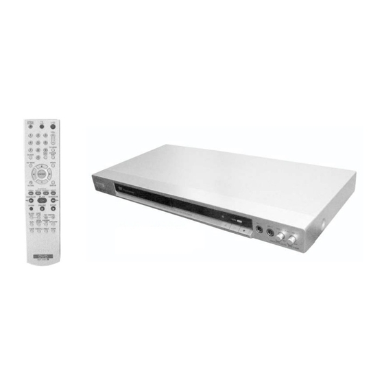
Photo : DVP-K88P
RMT-D181A
SPECIFICATIONS
DIGITAL OUT (COAXIAL): Phono jack/
0.5 Vp-p/75 ohms
COMPONENT VIDEO OUT
(Y, P
/C
, P
/C
):
B
B
R
R
Phono jack/Y: 1.0 Vp-p,
P
/C
, P
/C
: 0.7 Vp-p/75 ohms
B
B
R
R
(EXCEPT E,BR)
COMPONENT VIDEO OUT
(Y, P
, P
):
B
R
Phono jack/Y: 1.0 Vp-p/P
interlace
= 0.648 Vp-p, progressive or
*1
interlace
*2
= 0.7 Vp-p/75 ohms
BLACK LEVEL
*1
(COMPONENT OUT) is ON
*2
BLACK LEVEL
(COMPONENT OUT) is OFF
(E,BR ONLY)
LINE OUT (VIDEO): Phono jack/
1.0 Vp-p/75 ohms
MIC Input 1/2: Phone jacks
DVP-K88P/K88PM
RMT-D181A/RMT-D181P
General
Power requirements:
220 – 240 V AC, 50/60 Hz
(RUS ONLY)
110 – 240 V AC, 50/60 Hz
(EXCEPT RUS)
Power consumption: 10W
Dimensions (approx.):
430 × 43 × 214.4 mm
(width/height/depth) incl. projecting parts
, P
:
Mass (approx.): 1.80 kg
B
R
Operating temperature: 5°C to 35°C
Operating humidity: 25% to 80%
Supplied accessories
See page 14.
Specifications and design are subject to
change without notice.
CD/DVD PLAYER
E Model
Korea Model
Russian Model
Saudi Arabia Model
Singapore Model
Thailand Model
DVP-K88P
Brazilian Model
DVP-K88P/K88PM
Advertisement
Table of Contents

Related Manuals for Sony DVP-K88P


Summary of Contents for Sony DVP-K88P
- Page 1 SERVICE MANUAL Korea Model Russian Model Saudi Arabia Model Singapore Model Thailand Model DVP-K88P Brazilian Model DVP-K88P/K88PM Photo : DVP-K88P RMT-D181A SPECIFICATIONS DIGITAL OUT (COAXIAL): Phono jack/ System General 0.5 Vp-p/75 ohms Laser: Semiconductor laser Power requirements: Signal format system: COMPONENT VIDEO OUT 220 –...
- Page 2 THESE COMPONENTS WITH SONY PARTS WHOSE PART CRITIQUES POUR LA SÉCURITÉ DE FONCTIONNEMENT. NE NUMBERS APPEAR AS SHOWN IN THIS MANUAL OR IN REMPLACER CES COMPOSANTS QUE PAR DES PIÈSES SONY SUPPLEMENTS PUBLISHED BY SONY. DONT LES NUMÉROS SONT DONNÉS DANS CE MANUEL OU DANS LES SUPPÉMENTS PUBLIÉS PAR SONY.
-
Page 3: Table Of Contents
DVP-K88P/K88PM TABLE OF CONTENTS SERVICE NOTE Settings and Adjustments ............1-17 Using the Setup Display ........... 1-17 Setting the Display or Sound Track Language Disc Removal Procedure (at POWER OFF) ....... 5 (LANGUAGE SETUP) ..........1-17 Settings for the Display (SCREEN SETUP) ....1-17 Custom Settings (CUSTOM SETUP) ...... - Page 4 DVP-K88P/K88PM TEST MODE 6-1. Executing IOP Measurement ..........6-1 6-2. Emergency History Check ..........6-1 6-3. Initializing Setup Data ............6-2 6-4. Version Information ............. 6-3 6-5. If Con Self Diagnostic Function .......... 6-3 ELECTRICAL ADJUSTMENT 7-1. Power Supply Output Voltage Check ......... 7-1 7-2.
-
Page 5: Service Note
DVP-K88P/K88PM SERVICE NOTE 1. DISC REMOVAL PROCEDURE (at POWER OFF) 1) Open dust cover to access to a hole insert a tapering driver into the aperture of the unit bottom, and move the lever of chuck can in the direction of the arrow A. -
Page 6: General
• If the player is brought directly from a cold benzine, thinner, commercially nearest Sony dealer. available cleaners, or anti-static to a warm location, or is placed in a very spray intended for vinyl LPs. -
Page 7: Index To Parts And Controls
DVP-K88P/K88PM Copyrights Notes Index to Parts and Controls • Notes about DVD+RWs/DVD+Rs/DVD+Rs This product incorporates copyright DL, DVD-RWs/DVD-Rs/DVD-Rs DL or protection technology that is protected by CD-Rs/CD-RWs For more information, see the pages indicated in parentheses. U.S. patents and other intellectual property... -
Page 8: Guide To The Control Menu Display
DVP-K88P/K88PM List of Control Menu items Guide to the Control Menu Display Item Item Name, Function TITLE (page 31)/SCENE (page 31)/TRACK (page 31) Use the Control Menu to select a function and to view related information. Press DISPLAY Selects the title, scene, or track to be played. -
Page 9: Step 3: Connecting The Video Cords
DVP-K88P/K88PM If you are connecting to a video input jack Step 3: Connecting the Video Cords Connect the yellow plug of an audio/video cord (supplied) to the yellow (video) jack. You will enjoy standard quality images. Connect this player to your TV monitor, projector, or AV amplifier (receiver) using a video cord. -
Page 10: Step 5: Connecting The Mains Lead
DVP-K88P/K88PM Press X/x to select the type of Press ENTER. Step 5: Connecting the Mains Lead Dolby Digital signal you wish to The Setup Display for selecting the aspect ratio of the TV to be connected send to your amplifier (receiver). -
Page 11: Resuming Playback From The Point Where You Stopped The Disc (Multi-Disc Resume)
DVP-K88P/K88PM Notes Resuming Playback From Using the DVD’s Menu Selecting “ORIGINAL” or • “MULTI-DISC RESUME” in “CUSTOM the Point Where You “PLAY LIST” in DVD-VR SETUP” must be set to “ON” (default) for this function to work (page 71). Stopped the Disc mode •... -
Page 12: Searching For A Scene
DVP-K88P/K88PM Next, press X/x to select “03” under “C,” ◆ When Programme Play is activated ◆ When playing in DVD-VR mode Follow step 5 for new programming. To then press ENTER. cancel a programme, select “--” under • ON: shuffles titles, chapters, or tracks •... - Page 13 DVP-K88P/K88PM ◆ When playing a VIDEO CD or Super Press the number buttons to select Watching frame by frame Searching for a Title/ VCD without PBC Playback the title, chapter, track, index, (Slow-motion Play) TRACK Chapter/Track/Scene, scene, etc., number you want to INDEX search.
-
Page 14: Adjusting The Echo (Echo)
DVP-K88P/K88PM Press c. Dolby Digital Karaoke format Adjusting the Echo Changing the Key (ECHO) (KEY The following display appears. CONTROL) Dolby Digital format, which reproduces 0 1 2 3 4 5 surround sound using 5 channels, can also contain the “Dolby Digital Karaoke” format which is specialized for karaoke. -
Page 15: Adding Effects To Your Voice (Mic Effect)
DVP-K88P/K88PM Press c. Adding Effects to Your Turning the Guide Inserting the Applause The following display appears. Melody On and Off Voice Effect (GUIDE (MIC EFFECT) (APPLAUSE) MELODY) You can listen to the guide melody, if available. You can use this function to give high or low When using the Karaoke function, you can effects to your voice, as you sing. -
Page 16: Sound Adjustments
DVP-K88P/K88PM When playing a DVD When playing a DATA CD (DivX video) or Checking the play information of Notes DATA DVD (DivX video) • Depending on the type of disc being played, the the disc Playing time of the DVD/CD text or track name may not be... -
Page 17: Tv Virtual Surround Settings (Tvs)
L and R speakers is short, without using actual rear speakers (shown TVS was developed by Sony to produce such as with built-in speakers on a stereo TV. below). Use this setting when you want to use surround sound for home use using just a TVS with 2 separate speakers. -
Page 18: Sharpening The Picture (Sharpness)
DVP-K88P/K88PM Press X/x to select the setting you To cancel the “SHARPNESS” setting Adjusting the picture items in Sharpening the Picture Select “OFF” in step 3. want. “MEMORY” The default setting is underlined. (SHARPNESS) You can adjust each element of the picture •... -
Page 19: Playing Mp3 Audio Tracks Or Jpeg Image Files
DVP-K88P/K88PM Selecting an album Selecting an MP3 audio track Selecting a JPEG image file Playing MP3 Audio Tracks or JPEG Image Press MENU. After step 2 of “Selecting an album,” After step 2 of “Selecting an album,” press ENTER. The list of albums on the disc appears. -
Page 20: Enjoying Divx Videos
DVP-K88P/K88PM z Hints • SLOW 1: sets a duration longer than DivX video files that the player • To repeat both MP3 audio tracks and JPEG image NORMAL. ® files in a single album, repeat the same MP3 audio Enjoying DivX... -
Page 21: Using Various Additional Functions
ENTER. If your TV is listed in the table below, set the a new 4-digit password, replace the disc in the and power switch of your Sony TV with the The selection items for “LEVEL” are appropriate manufacturer’s code. -
Page 22: Settings And Adjustments
DVP-K88P/K88PM Press X/x to select “CUSTOM,” Press X/x to select a setting, then Setting the Display or then press ENTER. press ENTER. Settings and Adjustments Sound Track Language The Setup Display appears. The setting is selected and setup is complete. -
Page 23: Custom Settings (Custom Setup)
DVP-K88P/K88PM ◆ PAUSE MODE (DVDs only) Custom Settings Selects the picture in pause mode. (CUSTOM AUTO The picture, including subjects SETUP) DOLBY Normally, select this position. that move dynamically, is Settings for the Sound SUR- Multi-channel audio signals are output with no jitter. Normally... -
Page 24: Self-Diagnosis Function
, Contact your nearest DVD+RW (page 5) DTS (page 18, 73) sharper. This player is compatible with the Sony dealer or local 525 or 625 progressive format. A DVD+RW (plus RW) is a recordable and Digital audio compression technology that authorized Sony service rewritable disc. -
Page 25: Specifications
DVP-K88P/K88PM Specifications System General Laser: Semiconductor laser Power requirements: Signal format system: PAL/NTSC (See 110 – 240 V AC, 50/60 Hz page 16 to switch) Power consumption: 10 W Dimensions (approx.): 430 × 43 × 214.4 mm (width/height/ Audio characteristics Frequency response: DVD VIDEO (PCM depth) incl. -
Page 26: Disassembly
DVP-K88P/K88PM SECTION 2 DISASSEMBLY Note: Follow the disassembly procedure in the numerical order given. 2-1. UPPER CASE 4 Two Tapping Screws 6 Upper case 3 Tray Cover 5 Three Tapping Screws Chassis Back 2-2. FRONT PANEL ASSEMBLY, SW-493 BOARD and MC-174 BOARD... -
Page 27: Loading Assembly
DVP-K88P/K88PM 2-3. LOADING ASSEMBLY 4 Three Screws +BV3 (3-CR) 5 Loading Assembly 1 FMO-008 Flat Flexible Cable (CN101, 24P) 2 MD-111 Harness (CN201, 6P) 3 FMS-013 Flat Flexible Cable (CN202, 5P) -
Page 28: Optical Pick-Up (Device, Optical Khm-313Caa/C2Rp)
DVP-K88P/K88PM 2-4. OPTICAL PICK-UP Note: (DEVICE, OPTICAL KHM-313CAA/C2RP) Solder shortland before remove the FMO-008 Flat Flaxible Cable from 24 pin BU connector. 6 Two Insulator 3 Optical Device 5 FMO-008 Flat Flexible Cable (CN101, 24P) (KHM-313CAA/C2RP) 6 Two Insulator 4 MD-111 Harness (CN201, 6P) -
Page 29: Rear Panel, Mv-52 Board And If-150 Board
DVP-K88P/K88PM 2-5. REAR PANEL, MV-52 BOARD, IF-150 BOARD Note: Caution Point on the PWB IF-150 When handling IF-150 PWB avoid contact with the sharp metal edge on the top side of Vacuum Fluorescent Display (ND401). 6 FMO-008 Flat Flexible Cable... -
Page 30: Switching Regulator
DVP-K88P/K88PM 2-6. SWITCHING REGULATOR 2 Two Screws +BV3 (3-CR) 1 Connector (PM-136 Harness, CN201, 10P) 3 Power Board... -
Page 31: Interval Views
DVP-K88P/K88PM 2-7. INTERNAL VIEWS TOP VIEW MS-203 MOUNT BOTTOM VIEW... -
Page 32: Circuit Boards Location
DVP-K88P/K88PM 2-8. CIRCUIT BOARDS LOCATION Power Board MV-52 Board (SYSTEM, DRIVE, VIDEO, AUDIO, POWER) MC-174 Board (MIC-ECHO) SW-493 Board (SWITCH BOARD) IF-150 Board (INTERFACE) 2-7E... -
Page 33: Block Diagrams
DVP-K88P/K88PM SECTION 3 BLOCK DIAGRAMS 3-1. OVERALL BLOCK DIAGRAM SW-493 BOARD (SEE PAGE 3-13 to 3-14) FUNCTION ND401 IC406 MC-174 BOARD (SEE PAGE 3-11 to 3-12) IR RECEIVER MIC 1 IC503 IC502 IC501 MIC MIX MIC VOL MIC AMP MIC 2... -
Page 34: Power Line Block Diagram
DVP-K88P/K88PM 3-2. POWER LINE BLOCK DIAGRAM POWER BOARD (SRV1872WW) MV-52 BOARD (SEE PAGE 4-29 to 4-30) (SEE PAGE 4-15 to 4-24) T101 D411 L411 Q211 D211 L211 IC304 P.CONT Q712 Bridge Video Buffer POWER Rectifier Diode ACIN F101 2 Line... -
Page 35: System Control/Signal Processor Block Diagram
DVP-K88P/K88PM 3-3. SYSTEM CONTROL/SIGNAL PROCESSOR BLOCK DIAGRAM MV-52 BOARD (SEE PAGE 4-15 to 4-16) IC104 IC102 64M SDRAM 16M ROM 130~131,133~135,139~145 105~107,109~119,121~122 47,49~56,58~59,61~67,69,82~83 71~73,75~78,81 127 136 138 104 123 IC101 3.3Vp-p 121.5 MHz RESET IC IC 108 IC101 CXD9893R MICROPROCESSOR... -
Page 36: Rf/Servo Block Diagram
DVP-K88P/K88PM 3-4. RF/SERVO BLOCK DIAGRAM MV-52 BOARD BASE UNIT (SEE PAGE 4-17 to 4-18) (DEVICE, OPTICAL KHM-313CAA/C2RP) CN201 SPINDLE D04+ MOTOR D04- IN1- D03+ SLED D03- IN2- MOTOR LIMIT IN3- IN4- LIMIT D01+ IC201 DETECT D01- MOTOR DRIVER IC D02+... -
Page 37: Video Block Diagram
DVP-K88P/K88PM 3-5. VIDEO BLOCK DIAGRAM IC304 C/BAR PB MV-52 BOARD (SEE PAGE 4-19 to 4-20) XVMUTE 2.0Vp-p J301 IC304 COMBO JACK VIDEO BUFFER MV-52 CVBS SYSTEM CONTROL/ VIDEO_IN MUTE1 COMPONENT SIGNAL PROCESSOR VIDEO OUT (SEE PAGE 3-5 to 3-6) Y_IN... -
Page 38: Audio Block Diagram
DVP-K88P/K88PM 3-6. AUDIO BLOCK DIAGRAM MC-174 BOARD (SEE PAGE 4-11 to 4-12) RV501 MIC 1 LEVEL IC503 IC501 MIC MIX IC502 MIC AMP MIC 1 MIC VOL AMP J501 MIC 2 J502 RV502 MIC 2 LEVEL Q501, Q502, Q503 MIC DETECTION... -
Page 39: Interface Control Block Diagram
DVP-K88P/K88PM 3-7. INTERFACE CONTROL BLOCK DIAGRAM IF-150 BOARD (SEE PAGE 4-7 to 4-8) CN401 SW-10V IC407 EVER+5V 3.3V REGULATOR SYSRST SYSRST XIFCS EVER+3.3V SYSTEM CONTROL MV-52 (SEE PAGE 3-5 to 3-6) IC406 EVER+3.3V A-MUTE /AMUTE V-MUTE RECEIVER /VMUTE XIFBUSY BUSY... -
Page 40: Frame Schematic Diagram
DVP-K88P/K88PM SECTION 4 PRINTED WIRING BOARDS AND SCHEMATIC DIAGRAMS 4-1. FRAME SCHEMATIC DIAGRAM FRAME SCHEMATIC DIAGRAM... -
Page 41: Waveform
DVP-K88P/K88PM WAVEFORM 4-2. PRINTED WIRING BOARDS AND SCHEMATIC DIAGRAMS MV-52 BOARD THIS NOTE IS COMMON FOR WIRING BOARDS AND SCHEMATIC DIAGRAMS. (In addition to this, the necessary note is printed in each block) For printed wiring boards: IC101 (CD PB) - Page 42 DVP-K88P/K88PM IF-150 (INTERFACE) PRINTED WIRING BOARD For printed wiring board • : Uses unleaded solder. There are a few cases that the part printed on this diagram isn’t mounted in this model. IF-150 BOARD (SIDE A) Power Board MV-52 Board...
-
Page 43: Video) Schematic Diagram
DVP-K88P/K88PM For Schematic Diagram • Refer to page 4-5 to 4-6 for printed wiring board of IF-150 board. IF-150 BOARD TO CN105 INTERFACE MV-52 BOARD (SEE PAGE 4-15 TO 4-16) -REF.NO.:1000 SERIES- XX MARK:NO MOUNT NO MARK:PB MODE MARKED:MOUNT TABLE... - Page 44 DVP-K88P/K88PM MC-174 (MIC-ECHO) PRINTED WIRING BOARD For printed wiring board • : Uses unleaded solder. There are a few cases that the part printed on this diagram isn’t mounted in this model. MC-174 BOARD (SIDE A) Power Board MV-52 Board...
- Page 45 DVP-K88P/K88PM For Schematic Diagram • Refer to page 4-9 to 4-10 for printed wiring board of MC-174 board. MC-174 BOARD MIC-ECHO -REF.NO.:1000 SERIES- XX MARK:NO MOUNT NO MARK:PB MODE MARKED:MOUNT TABLE TO CN201 MV-52 BOARD (AUDIO) (SEE PAGE 4-21 TO 4-22)
- Page 46 DVP-K88P/K88PM MV-52 (SYSTEM, DRIVE, VIDEO, AUDIO, POWER) PRINTED WIRING BOARD For printed wiring board • : Uses unleaded solder. There are a few cases that the part printed on this diagram isn’t mounted in this model. MV-52 BOARD (SIDE A)
- Page 47 DVP-K88P/K88PM For Schematic Diagram • Refer to page 4-13 to 4-14 for printed wiring board of MV-52 board. • Refer to page 4-3 to 4-4 for waveform MV-52 BOARD (1/5) SYSTEM -REF.NO.:1000 SERIES- XX MARK:NO MOUNT NO MARK:REC/PB MODE TO CN 401...
- Page 48 DVP-K88P/K88PM For Schematic Diagram • Refer to page 4-13 to 4-14 for printed wiring board of MV-52 board. • Refer to page 4-3 to 4-4 for waveform MV-52 BOARD (2/5) DRIVE -REF.NO.:1000 SERIES- XX MARK:NO MOUNT NO MARK:REC/PB MODE DRIVE...
- Page 49 DVP-K88P/K88PM For Schematic Diagram • Refer to page 4-13 to 4-14 for printed wiring board of MV-52 board. • Refer to page 4-3 to 4-4 for waveform MV-52 BOARD (3/5) VIDEO -REF.NO.:1000 SERIES- XX MARK:NO MOUNT NO MARK:REC/PB MODE VIDEO...
- Page 50 DVP-K88P/K88PM For Schematic Diagram • Refer to page 4-13 to 4-14 for printed wiring board of MV-52 board. • Refer to page 4-3 to 4-4 for waveform MV-52 BOARD (4/5) AUDIO -REF.NO.:1000 SERIES- XX MARK:NO MOUNT TO CN501 MC-174 BOARD...
- Page 51 DVP-K88P/K88PM For Schematic Diagram • Refer to page 4-13 to 4-14 for printed wiring board of MV-52 board. • Refer to page 4-3 to 4-4 for waveform MV-52 BOARD (5/5) POWER -REF.NO.:1000 SERIES- XX MARK:NO MOUNT NO MARK:REC/PB MODE The components identified by...
- Page 52 DVP-K88P/K88PM SW-493 (SWITCH BOARD) PRINTED WIRING BOARD For printed wiring board • : Uses unleaded solder. There are a few cases that the part printed on this diagram isn’t mounted in this model. SW-493 BOARD (SIDE A) SW-493 BOARD (SIDE B)
-
Page 53: Power Block (Srv1872Ww) Printed Wiring Board
DVP-K88P/K88PM POWER BLOCK (SRV1872WW) PRINTED WIRING BOARD For printed wiring board • : Uses unleaded solder. There are a few cases that the part printed on this diagram isn’t mounted in this model. POWER BOARD (SRV1872WW) (SIDE A) Power Board... - Page 54 DVP-K88P/K88PM For Schematic Diagram • Refer to page 4-27 to 4-28 for printed wiring board of Power board. POWER BOARD POWER SUPPLY (SRV1872WW) -REF.NO.:1000 SERIES- XX MARK:NO MOUNT NO MARK:PB MODE MARKED:MOUNT TABLE EVER-10V POWER SW P-CONT TO CN501 SW+5V...
-
Page 55: Ic Pin Function Description
DVP-K88P/K88PM SECTION 5 IC PIN FUNCTION DESCRIPTION 5-1. SYSTEM CONTROL PIN FUNCTION (MV-52) Pin No. Pin name Type Function AGND Ground Ground pin for analog circuitry DVDA Analog Input AC coupled input path A DVDB Analog Input AC coupled input path B... - Page 56 DVP-K88P/K88PM Pin No. Pin name Type Function Output PU Host address bit3 Output PU Host address bit4 Output PU Host address bit5 Output PU Host address bit6 Output PU Host address bit7 Output PU Host address bit8 HA18 Output SMT, PD...
- Page 57 DVP-K88P/K88PM Pin No. Pin name Type Function 8032 external interrupt 0 (for ICE) DQM0 Output Mask for DRAM input/output byte 0 Output DRAM data bit7 Output DRAM data bit6 Output DRAM data bit5 DVDD3 Power 3.3V power pin for internal digital circuitry...
- Page 58 DVP-K88P/K88PM Pin No. Pin name Type Function GPIO Not Used GPIO Not Used Not Used SPDIF Output SPDIF output DACVDDC Power 3.3V power for Video DAC circuitry VREF Analog Input Bandgap Ref Voltage (No connect) Analog Input Full Scale Adjustment...
- Page 59 DVP-K88P/K88PM Pin No. Pin name Type Function HRFZC Analog Input High frequency RF ripple zero crossing CRTPLP Analog Output Defect level filter capacitor connecting RFGND Ground Ground pin for RF digital circuitry Analog Output RF Offset cancellation capacitor connecting Analog Output...
-
Page 60: Test Mode
DVP-K88P/K88PM SECTION 6 TEST MODE 6-1. EXECUTING IOP MEASUREMENT Wait until a hexadecimal number appear. Manual Adjust In order to execute IOP measurement, the following standard procedures must be followed. 1. Track Balance Adjust: 2. Track Gain Adjust: In standby mode, press [TOP MENU], [CLEAR], [POWER] to 3. -
Page 61: Initializing Setup Data
DVP-K88P/K88PM Error code list (10) How to Clearing Emergency code 01: Communication error (No reply from syscon) Press [TOPMENU], [CLEAR] keys in this order. 02: Syscon hung up All emergency code are cleared. 03: Power OFF request when syscon hung up Emg. -
Page 62: Version Information
DVP-K88P/K88PM The Emergency history display screen will be restored soon. 6-5. IF CON SELF DIAGNOSTIC FUNCTION Emg. History Check IF-150 BOARD (IF CON) TEXT MODE The IF-150 board (IF CON) test mode is the IF CON self-diagnosis Laser Hours 999h 59min mode. - Page 63 DVP-K88P/K88PM 2-2. Operation of Auto Self Check When the Self Check mode becomes active at the AC Power ON or by key input, the test display of the following steps (1) to (4) is repeated. FLD and all ON (for 5 seconds)
- Page 64 DVP-K88P/K88PM 2-3-1. FLD All ON 2-3-1-1. Transition Keys in Self Check Mode • Z key and x key on the main unit • T key on the remote commander 2-3-1-2. Operation and display In this mode, all segments of FLD turn ON.
- Page 65 DVP-K88P/K88PM 2-3-3. Remote Commander Key Name Display and Key Code Display 2-3-3-1. Transition Keys in Self Check Mode • Remote commander keys except keys transited in Self Check Mode 2-3-3-2. Operation and Display When a key on the remote commander is pressed in the Self Check Mode, the name of that key is displayed on the FLD. Aslo, the key name display and the key code display can be switched with the [DISPLAY] key on the remote commander.
- Page 66 DVP-K88P/K88PM 2-3-5. FLD Anode Test Display and SHUTTLE Click Operation Test 2-3-5-1. Transition Keys in Self Check Mode • t key on the remote commander • SHUTTLE on the remote commander during Anode Test display (This unit does not provide JOG/SHUTTLE, and therefore use another DVD remote commander having the JOG/SHUTTLE) 2-3-5-2.
- Page 67 DVP-K88P/K88PM 2-3-7. LED Test Display 2-3-7-1. Transition Keys in Self Check Mode • key on the remote commander • SHUTTLE on the remote commander during Grid Test display (This model does not provide JOG/SHUTTLE, and therefore use another DVD remote commander having the JOG/SHUTTLE) 2-3-7-2.
- Page 68 DVP-K88P/K88PM (5G, 3G) (7G~2G) (7G~1G) ANODE CONNECTION 6-9E...
-
Page 69: Electrical Adjustment
DVP-K88P/K88PM SECTION 7 ELECTRICAL ADJUSTMENT This section describes procedures and instructions necessary for 7-1. POWER SUPPLY OUTPUT VOLTAGE adjusting electrical circuits in this unit. CHECK Instruments required: Mode Except standby Color monitor TV Instrument Digital multimeter Oscilloscope 1 or 2 phenomena, band width over 100 MHz, with... -
Page 70: Adjustment Of Video System
DVP-K88P/K88PM 7-3. ADJUSTMENT OF VIDEO SYSTEM Checking Component Video Output B-Y <Purpose> Checking Video Level This checks component video output B-Y. If it is incorrect, correct <Purpose> colors will not be displayed when connected to, for instance, projector. Checking Video Level the NTSC/PAL standard, and if not correct, the brightness will be too large or small. -
Page 71: Repair Parts List
DVP-K88P/K88PM SECTION 8 REPAIR PARTS LIST 8-1. EXPLODED VIEWS The components identified by mark or dotted line with mark critical for safety. NOTE: Replace only with part number • -XX and -X mean standardized parts, so • Abbreviation specified. they may have some difference from the : Brazilian Model original one. - Page 72 Ref. No. Part No. Description Remark 1 3-077-331-11 +BV3 (3-CR) 2 3-077-331-21 +BV3 (3-CR) 3 1-830-279-21 FLEXIBLE FLAT CABLE (FMO-008) * 4 1-833-761-11 CABLE, FLEXIBLE FLAT (FMS-013) 5 3-081-834-21 BATTERY COVER (SMK7G) * 6 2-319-080-01 COVER, TRAY (EXCEPT BR) 2-319-080-11 COVER, TRAY (BR) * 7 ...
-
Page 73: Mechanism Deck Assembly
DVP-K88P/K88PM 8-1-2. MECHANISM DECK ASSEMBLY ns : not supplied Ref. No. Part No. Description Remark A-6071-669-A LOADING ASSY(M) 3-088-372-01 INSULATOR 3-087-599-01 INSULATOR SCREW 4-674-137-11 SCREW (PTP2X5) 3-088-371-01 BELT 4-974-725-11 SCREW (M1.7X2.5), P 8-820-321-05 DEVICE,OPTICAL KHM-313CAA/C2RP Note : The components identified by mark... -
Page 74: Electrical Parts List
DVP-K88P/K88PM IF-150 The components identified by mark 8-2. ELECTRICAL PARTS LIST or dotted line with mark critical for safety. NOTE: Replace only with part number specified. • Due to standardization, replacements in • SEMICONDUCTORS the parts list may be different from the In each case, u: µ, for example:... - Page 75 DVP-K88P/K88PM IF-150 MC-174 Ref. No. Part No. Description Remark Ref. No. Part No. Description Remark 0.001UF 5.00% R419 1-216-073-91 RES, CHIP 10K (2012) C524 1-115-416-11 CERAMIC CHIP 330PF R420 1-216-027-00 RES-CHIP 1/10W C525 1-162-959-11 CERAMIC CHIP 5.00% R421 1-216-013-00 RES-CHIP...
- Page 76 DVP-K88P/K88PM MC-174 MV-52 Ref. No. Part No. Description Remark Ref. No. Part No. Description Remark R507 1-216-089-91 RES, CHIP 47K (2012) C113 1-162-970-11 CERAMIC CHIP 0.01UF 10.00% R508 1-216-073-91 RES, CHIP 10K (2012) C114 1-107-826-11 CERAMIC CHIP 0.1UF 10.00% R509...
- Page 77 DVP-K88P/K88PM MV-52 Ref. No. Part No. Description Remark Ref. No. Part No. Description Remark C181 1-107-826-11 CERAMIC CHIP 0.1UF 10.00% C415 1-164-230-11 CERAMIC CHIP 220PF 5.00% C182 1-127-715-91 CERAMIC CHIP 0.22UF C416 1-164-230-11 CERAMIC CHIP 220PF 5.00% C184 1-162-970-11 CERAMIC CHIP 0.01UF...
- Page 78 DVP-K88P/K88PM MV-52 Remark Ref. No. Part No. Description Remark Ref. No. Part No. Description <RESISTOR> <IC> R101 1-216-809-11 METAL CHIP 1/10W Notes: R102 1-216-864-11 SHORT CHIP MV-52 mounted PWB must be replaced if R106 1-216-833-11 METAL CHIP 1/10W IC103 (EEPROM IC) is damaged or not functioning.
- Page 79 DVP-K88P/K88PM MV-52 Ref. No. Part No. Description Remark Ref. No. Part No. Description Remark R209 1-216-839-11 METAL CHIP 1/10W R430 1-216-841-11 METAL CHIP 1/10W R210 1-216-841-11 METAL CHIP 1/10W R431 1-216-833-11 METAL CHIP 1/10W R212 1-216-833-11 METAL CHIP 1/10W R432...
- Page 80 DVP-K88P/K88PM MV-52 SW-493 POWER BLOCK (SRV1872WW) Ref. No. Part No. Description Remark Ref. No. Part No. Description Remark R1101 1-218-841-11 METAL CHIP 0.5% 1/10W SW-493 BOARD R1102 1-218-827-11 METAL CHIP 0.5% 1/10W ******************** R1103 1-216-833-11 METAL CHIP 1/10W R1105 1-216-864-11...
- Page 81 DVP-K88P/K88PM 2007G1100-1 Sony Corporation 2008.03 Home Electronics Network Company. 9-883-942-13 Published by Product Design 1 Department – 103 –...
Need help?
Do you have a question about the DVP-K88P and is the answer not in the manual?
Questions and answers