Table of Contents
Advertisement
DVP-NS15/NS51P/NS43P/NS53P/K56P
SERVICE MANUAL
RMT-D175P
RMT-D175A
Notes: Australia/NZ model only
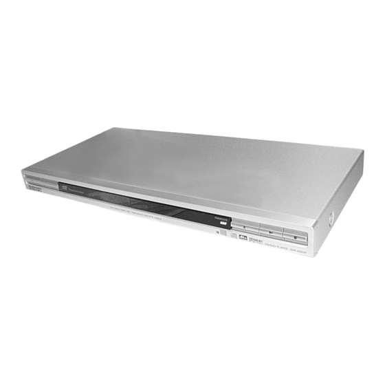
This manual have
three different type
of DVD player
appearance/structure .
Please take note.
Photo : DVP-NS15
Photo : DVP-NS51P
Photo : DVP-K56P
Photo : DVP-NS43P/NS53P
/RMT-D175C/RMT-D175P
RMT-D175A
Australian/New Zealand Model
IND,PAK,MAR Model
CD/DVD PLAYER
AEP Model
UK Model
DVP-NS15
Chinese Model
DVP-NS51P
Argentina Model
Brazilian Model
DVP-NS43P/NS53P
Singapore Model
Saudi Arabia Model
DVP-NS51P/K56P
Mexican Model
E Model
DVP-NS53P
Russian Model
DVP-K56P
Taiwan Model
DVP-K56P/NS51P
India Model
Iran Model
Middle East Model
Korean Model
Malaysian Model
Hong Kong Model
Vietnam Model
DVP-NS51P
Advertisement
Table of Contents


Need help?
Do you have a question about the DVP-NS15 and is the answer not in the manual?
Questions and answers