
Related Manuals for Phoenix Model tucano 40


Summary of Contents for Phoenix Model tucano 40
-
Page 1: Instruction Manual
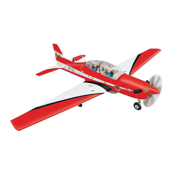
Instruction Manual Wing span: 1560 mm (61.4 inches) Length: 1250 mm (49.2 inches) Weight: 2800 gr Engine: 40 - 46 two strokes Radio : 4 channels Servos : 5 standard... -
Page 2: Kit Contents
KIT CONTENTS: We have organized the parts as they come out of the box for better identification during assembly. We recommend that you regroup the parts in the same manner. This will ensure you have all of parts required before you begin assembly. KIT CONTENTS AIR FRAME ASSEMBLIES RUDDER CONTROL SYSTEM... - Page 3 This will assure proper assembly. The Tucano 40 ARF is hand made from natural materials, every plane is unique and minor 3. Using a modeling knife, remove the covering adjustments may have to be made.
- Page 4 5. Place the servo into the servo tray. Center the servo within the tray and drill 1,6mm pilot holes through the block of wood for each of the four Masking Tape mounting screws provided with the servo. INSTALLING THE DIHEDRAL BRACE 1.
- Page 5 5. When satisfied with the fit of the wing halves, AILERON LINKAGE remove the wing halves and the dihedral brace. PARTS REQUIRED · (2) 2mm x 180mm Thread wires. · (2) Nylon control horns. JOINING THE WING HALVES · (2) Clevis. 1.
- Page 6 4. Plug the aileron servo into the receiver and center the servo. Install the servo arm onto the Draw a center line servo. The servo arm should be perpendicular to the servo and point toward the middle of the wing. 5.
- Page 7 2. Slide the vertical stabilizer into the slot in the mounting platform in the top of the fuselage. Mark Remove the covering the shape of the fuselage on the left and right sides of the vertical stabilizer using a felt-tip pen. 6.
- Page 8 LANDING GEAR INSTALLATION 4. Install two of the wheels onto the axles using the four wheel collars and set screws provided. PARTS REQUIRED The wheels should be centered on the axles • (1) Nose gear • (1) Steering arm with a wheel collar on each side, holding them •...
- Page 9 ENGINE INSTALLATION PARTS REQUIRED • (4) 3mm x 25mm wood screw • (1) 1.3mm x 500mm wire. down thrust • (1) 3.5mm x 350mm nylon pushrod housing. right thrust • (1) Metal connector. FUEL TANK INSTALLING THE THROTTLE PUSHROD HOUSING PARTS REQUIRED 1.
- Page 10 7. Using a modeling knife, cut 3 lengths of fuel line INSTALLING THE ELEVATOR PUSHROD 150mm long. Connect 2 lines to the 2 vent tubes PARTS REQUIRED and 1 line to the fuel pickup tube in the stopper. · (1) Clevis 8.
- Page 11 9. Locate one nylon servo arm, and using wire cutters, 6. Drill two 1,6mm holes through the rudder using remove all but one of the arms. Using a 2mm drill the control horn as a guide and screw the bit, enlarge the third hole out from the center to control horn in place.
- Page 12 2. Insert the nosegear pushrod wire through the MOUNTING THE COWL adjustable servo connector on the rudder PARTS REQUIRED servo arm. Hold the nose gear assembly in · (1) fiberglass cowl the neutral position and tighten the set screw · (4) 2,6mm x 10mm in the servo connector.
- Page 13 - Glue the plastic antenna. INSTALLING THE WING 1. Using a modeling knife, remove the covering from over the two pre-drilled holes in the forward bulkhead that accept the wing hold down dowels. 2. Using a modeling knife, remove the covering from over the two pre-drilled wing mounting holes in the trailing edge of the wing.
-
Page 14: Control Throws
CONTROL THROWS Receiver Baterry 1. We highly recommend setting up a plane using the control throws listed. 2. The control throws should be measured at the widest point of each control surface. 3. Check to be sure the control surfaces move in the correct directions. -
Page 15: Metric Conversions
I/C FLIGHT WARNINGS Always operate in open areas, away Keep all onlookers (especially small from factories, hospitals, schools, THE PROPELLER IS DANGEROUS children and animals) well back from buildings and houses etc. NEVER fly Keep fingers, clothing (ties, shirt the area of operation. This is a flying your aircraft close to people or built sleeves, scarves) or any other loose aircraft, which will cause serious... - Page 16 I/C FLIGHT GUIDELINES Operate the control sticks on the When ready to fly, first extend the transmitter and check that the control transmitter aerial. surfaces move freely and in the ALWAYS land the model INTO the CORRECT directions. wind, this ensures that the model lands at the slowest possible speed.
Need help?
Do you have a question about the tucano 40 and is the answer not in the manual?
Questions and answers