Table of Contents
Advertisement
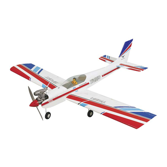
SPECIFICATION
- Wingspan: 1600mm (63in)
- Length: 1360mm (53.5 in)
- Flying weight: 2500-2700 gr
- Wing area: 42.8 dm2
- Wing loading: 60g/dm2
- Wing type: Naca airfoils
- Covering type: V-kote film
- Spinner size: Plastic 58mm (included)
- Radio: 4 channel minimum (not included)
- Servo: 5 standard servo: 2 aileron;
1 elevator; 1 rudder; 1 throttle (not included)
- Recommended receiver battery:
4.8-6V / 800-1200mAh NiMH (not included)
- Servo mount: 21mm x 42 mm
- Propeller: suit with your engine
- Engine: .46-.55 / 2-stroke (not included)
Instruction Manual
- Motor: brushless outrunner 1000-1400 W,
480 KV (not included)
- Gravity CG: 75-85 mm (2.9-3.3 in) Back from
the leading edge of the wing, at the fuselage
- Control throw Ailerons: Low: 8mm up/down,
10% expo; High: 10mm up/down, 10% expo
- Control throw Elevators: Low: 8mm up/down,
12% expo; High: 10mm up/down, 12% expo
- Control throw Rudder: Low: 25mm right/left,
15% expo; High: 40mm right/left, 15% expo
- Experience level: Intermediate
- Plane type: Low wing sport
RECOMMENDED MOTOR AND BATTERY SET UP
- Motor: RIMFIRE .46 (not included)
- Lipo cell: 6cells / 4000-5000mAh (not included)
- Esc: 50-70A (not included)
GP
EP
version
version
Advertisement
Table of Contents

Subscribe to Our Youtube Channel
Related Manuals for Phoenix Model TIGER 3


Summary of Contents for Phoenix Model TIGER 3
- Page 1 Instruction Manual version version SPECIFICATION - Wingspan: 1600mm (63in) - Motor: brushless outrunner 1000-1400 W, - Length: 1360mm (53.5 in) 480 KV (not included) - Flying weight: 2500-2700 gr - Gravity CG: 75-85 mm (2.9-3.3 in) Back from - Wing area: 42.8 dm2 the leading edge of the wing, at the fuselage - Wing loading: 60g/dm2 - Control throw Ailerons: Low: 8mm up/down,...
-
Page 2: Tools And Supplies Needed
This will assure proper assembly. The TIGER 3 GP/EP SIZE .46-.55 SCALE 1:6 is hand made from natural materials, every plane is unique and minor adjustments may have to be made. - Page 3 Instruction Manual tiger < Bottom view of left wing> Aileron Aileron Servo Cut away film only. here 1.5mm Supplied with the servo Must be purchased separately! 1.5mm Assemble left and right sides the same way < For right side > <...
-
Page 4: Installing The Control Horns
Instruction Manual tiger INSTALLING THE CONTROL HORNS 3. Repeat step # 1 - # 2 to install the control horn on the opposite aileron. 1. One aileron control horn in positioned on each aileron. Using a ruler and a pen, locate and mark the location of the control horn. -
Page 5: Installing The Main Landing Gear
Instruction Manual tiger Wing Assembly 4) Insert the dihedral brace into one wing half up to the centerline. Wipe off any excess epoxy that may *Note* We highly recommend using 30 Minute Epoxy have squeezed out of the joint using paper towels. over faster curing epoxies for several reasons. -
Page 6: Horizontal Stabilizer Installation
Instruction Manual tiger INSTALLING THE NOSE GEAR 3 x 12mm Screw 3x12mm 3x12mm Apply threadlocker (screw cement). Installing SECURE The Wing To The Fuselage Attach the wings to the fuselage and using the nylon 6x45mm thumbscrews to secure the wing panels. 6x45mm Plastic Screw 4. -
Page 7: Vertical Stabilizer Installation
Instruction Manual tiger When you are sure that everything is aligned 7. After the epoxy has fully cured, remove the masking correctly, mix up a generous amount of 30 minute tape or T-pins used to hold the stabilizer in place epoxy. -
Page 8: Installing The Rudder Pushrod
Instruction Manual tiger 5. When you are sure that everything is a aligned correctly, mix up a generous amount of 30 minute epoxy. Apply a thin layer to the slot in the mounting platform and to the vertical stabilizer mounting area. Apply epoxy to the lower rudder hinge. - Page 9 Instruction Manual tiger 2 x 16mm TP Screw 2x16mm Cut off excess. approx. 13mm Set all screws securely. If they come off during flight you will lose control of your aircraft! Must be purchased separately! Cut off shaded portion Apply threadlocker (screw cement). Ensure smooth, non-binding movement when assembling Rudder rod...
-
Page 10: Installing The Elevator Pushrod
Instruction Manual tiger INSTALLING THE ELEVATOR PUSHROD 9. Plug the elevator servo into the receiver and center the servo. Install the servo arm onto the 1. Locate the pushrod exit slot on the right side servo. The servo arm should be perpendicular to the servo and point toward the middle of the and left side of the fuselage. -
Page 11: Installing The Engine Mount
Instruction Manual tiger Elevator Elevator Rod Elevator Rod 3x4mm Pay close attention here Install the horn in a position so the rod is straight Cut off excess. INSTALLING THE ENGINE MOUNT Apply threadlocker (screw cement). FUEL TANK INSTALLATION 1. Assemble the fuel tank. 2. -
Page 12: Installing The Engine
Instruction Manual tiger Cut off shaded portion INSTALLING THE THROTTLE PUSHROD SERVO 3. Apply epoxy glue to the pushrod housing where it exits the firewall and where it passes through the 1. Place the engine into the engine mount and align it forward bulkhead. -
Page 13: Installing The Throttle
Instruction Manual tiger 3x25mm 3x25mm INSTALLING THE THROTTLE 1. Install one adjustable metal connector through the third hole out from the center of one servo arm, enlarge the hole in the servo arm using a 2mm drill bit to accommodate the servo connector. -
Page 14: Installing The Spinner
Instruction Manual tiger Adjust the throttle input (transmitter throttle stick), throttle trim movement and the carburattor opening to the suitable position and screw in the 4x4mm set screw. INSTALLING THE SPINNER 3 x 15mm Install the spinner back-plate, propeller and spinner cone. -
Page 15: Installing The Receiver And Battery
Instruction Manual tiger INSTALLING THE RECEIVER AND BATTERY INSTALLING THE SWITCH 1. Plug the servo leads and the switch lead into the 1. The switch should be mounted on the fuselage receiver. You may want to plug an aileron side, opposite the muffler, close enough to the extension into the receiver to make plugging in the receiver so the lead will reach. - Page 16 Instruction Manual tiger Must be purchased separately! Follow instruction manual of Motor and ESC. < Check the motor rotation > When rotating clock wise, charge the connection of 2 wires. Hatch BALANCING Turn the airplane upside down. Place your fingers on the masking tape and carefully lift It is critical that your airplane be balanced the plane .
-
Page 17: Lateral Balance
Instruction Manual tiger 75-85mm (2.9-3.3 in) LATERAL BALANCE After you have balanced a plane on the C.G. You should laterally balance it. Doing this will FLIGHT PREPARATION PRE FLIGHT CHECK help the airplane track straighter Completely charge your transmitter and 1. - Page 18 Instruction Manual tiger FOR YOUR RADIO INSTALLATION BASIC CONNECTION FOR AIRPLANE AND ADJUSTMENT OF SERVOS Example of connection For more information, refer to radio system instruction manual. Follow instruction manual of Engine and Battery. Switch Battery (Receiver) Receiver Nose wheel Rudder Servo Rudder Y-Harness...
- Page 19 2x16mm(TP) 2x16mm(TP) 6x45mm(TP) 2x10mm(TP) 2x16mm(TP) 3x12mm(TP) 3x4mm 4x4mm 3x15mm(TP) 2x16mm(TP) 3x12mm(TP) 3x12mm(TP) 2x10mm(TP) 3x25mm 4x60mm 4x4mm...
- Page 20 I/C FLIGHT GUIDELINES Operate the control sticks on the When ready to fly, first extend the transmitter and check that the control transmitter aerial. surfaces move freely and in the ALWAYS land the model INTO the CORRECT directions. wind, this ensures that the model lands at the slowest possible speed.
Need help?
Do you have a question about the TIGER 3 and is the answer not in the manual?
Questions and answers