Table of Contents
Advertisement
I n s t r u c t i o n M a n u a l
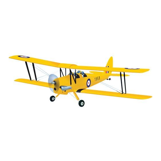
Fly the Tiger Moth biplane - Phoenix Model' ARF version makes it economical
and easy! Built from light weight, high - quality balsa. The fiber glass cowl
painted by hand to match the trim scheme. Most part are cut by laser machine.
Computer - designed for easy assembly. Semi - symmetrical clark Y-airfoils and
ailerons on both wings give these scale versions the original's agility. Includes
main and tail gear, wheels, fuel tank, linkage parts set and decals.
Specification:
Wingspan
Wing Area
Length
Weight approx : 2600 - 2800g (5.7 - 6.2lb)
Radio control
Engine
: 144cm (56.7 in)
: 58 dm 2
: 112cm (44 in)
: 4 channel / 5 servos
: 2 stroke. 40 class 4 stroke .48 - .53 class
Advertisement
Table of Contents

Related Manuals for Phoenix Model TIGER MOTH 40


Summary of Contents for Phoenix Model TIGER MOTH 40
- Page 1 I n s t r u c t i o n M a n u a l Fly the Tiger Moth biplane - Phoenix Model' ARF version makes it economical and easy! Built from light weight, high - quality balsa. The fiber glass cowl painted by hand to match the trim scheme.
-
Page 2: Kit Contents
KIT CONTENTS: We have organized the parts as they come out of the box for better identification during assembly. We recommend that you regroup the parts in the same manner. This will ensure you have all of parts required before you begin assembly KIT CONTENTS AIR FRAME ASSEMBLIES rudder control system... -
Page 3: Tools And Supplies Needed
This will assure proper assembly. The TIGER MOTH 40 is hand made from natural materials, every plane is unique and minor adjustments may have to be made. However, you should find the fit superior and assembly simple. -
Page 4: Installing The Aileron Linkages
5. Place the aileron servo tray / hatch into the servo box on the bottom of the wing and drill 1,6mm pilot holes through the tray and the servo box for each of the four mounting screws. Secure the servo tray in place using the mounting screws provided ( 2mm x 12mm ). -
Page 5: Installing The Horizontal Stabilizer
INSTALLING THE HORIZONTAL STABILIZER 1. Using a modeling knife, cut away the covering from the fuselage for the stabilizer and remove it. To the cowl Silicone Tube 9. Repeat step # 4 - # 8 to install the second aileron linkage. After both linkages are completed, connect both of the aileron servo leads using a Y-harness you have purchased separately. -
Page 6: Installing The Vertical Stabilizer
6. Attach the lower wing to the fuselage as picture. 9. After the epoxy has fully cured, remove the masking tape or T-pins used to hold the stabilizer in place and carefully inspect the glue joints. Use more epoxy to fill in any gaps that were not filled previously and clean up the excess using a paper towel and rubbing alcohol. -
Page 7: Installing The Landing Gear
3. Remove the covering 7. Secure the tail gear. 4. Prepare the tail gear as shown. INSTALLING THE LANDING GEAR 1. Remove the covering. 50mm 5. Glue the rudder hinge by C.A glue. 2. Install the wheel and secure it. 6. -
Page 8: Engine Installation
4. Attach and glue the plastic cover for the landing gear. 110mm ENGINE INSTALLATION down thrust INSTALLING THE THROTTLE PUSHROD HOUSING 1. Install the engine mount into the fire wall using right thrust 4mm x 25mm screw. 2. Place the engine into the engine mount and FUEL TANK align it properly with the front of the cowling. -
Page 9: Installing The Elevator Pushrod
5. Test fit the stopper assembly into the tank. It SERVO INSTALLATION may be necessary to remove some of the INSTALLING THE FUSELAGE SERVOS flashing around the tank opening using a modeling knife. If flashing is present, make 1. Install the rubber grommets and brass collets sure none of it falls into the tank. -
Page 10: Installing The Rudder Pushrod
Metal domino Control horn Control horn 7. Attach clevis to the third hole in the control INSTALLING THE RUDDER PUSHROD horn. Install a silicone tube on the clevis. 1. Locate the pushrod exit slot on the left of the fuselage. 2. -
Page 11: Mounting The Cowl
8. Locate one nylon servo arm, and using wire Manually push the carburator barrel fully cutters, remove all but one of the arms using a closed. Angle the arm back about 45 degree 2mm drill bit, enlarge the third hole out from the from center and attach the servo arm onto the center to accommodate the rudder pushrod servo. -
Page 12: Installing The Switch
2. Wrap the receiver and battery pack in the protective foam to protect them from vibration. Use a rubber band or masking tape to hold the foam in place. 3. Strap the battery pack and receiver onto the wing joiner tube in the fuselage. Do not permanently secure the receiver and battery until after balancing the model. - Page 13 2. Install two aluminum plate to the lower wing. 5. Install two metal strap to the upper wing as picture below. Screw Aluminum plate 6. Install the wing strut as picture below. Screw 3. Install the metal strap to the lower wing as picture below.
-
Page 14: Installing The Canopy
INSTALLING THE CANOPY Canopy Screw Front Wing strut Aluminum plate Screw 9. Install the cable. Short BALANCING 1. It is critical that your airplane be balanced correctly. Improper balance will cause your plane to lose control and crash. Long THE CENTER OF GRAVITY IS LOCATED 45mm Front BACK FROM THE LEADING EDGE OF THE WING, AT THE FUSELAGE. -
Page 15: Lateral Balance
LATERAL BALANCE 10mm After you have balanced a plane on the C.G. 10mm You should laterally balance it. Doing this will help the airplane track straighter. Elevator Control 1. Turn the airplane upside down. Attach one loop of heavy string to the engine crankshaft and 30mm one to the tail wheel wire. - Page 16 I/C FLIGHT GUIDELINES Operate the control sticks on the When ready to fly, first extend the transmitter and check that the control transmitter aerial. surfaces move freely and in the ALWAYS land the model INTO the CORRECT directions. wind, this ensures that the model lands at the slowest possible speed.
Need help?
Do you have a question about the TIGER MOTH 40 and is the answer not in the manual?
Questions and answers