
Related Manuals for Phoenix Model Tiger 60


Summary of Contents for Phoenix Model Tiger 60
-
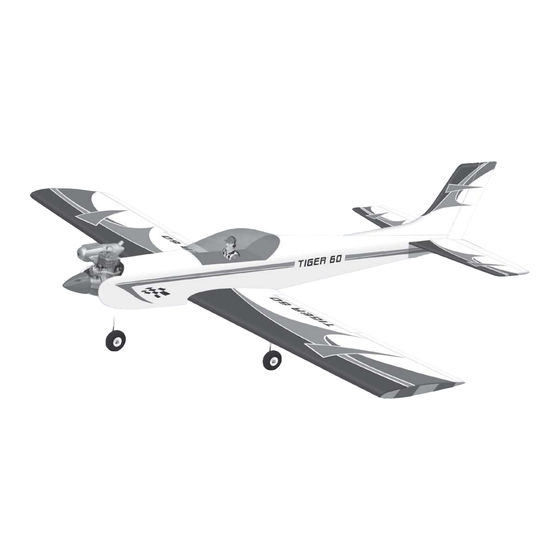
Page 1: Instruction Manual
Instruction Manual Wingspan : 1700 mm (66.9 in) Length : 1470 mm (57.9 in) Weight : 3200g - 3500g Radio : 6 channel / 7 servo Engine : 61 two stroke/70 four stroke... - Page 2 Installing the aileron and flap servos. Installing the aileron and flap servos. Extension servo Remove the covering from the top of Remove the covering from the aileron Prepare the aileron servo. the wing. servo box (at the bottom of the wing). Tape the servo lead into the end of the Insert the thread into the wing.
- Page 3 Bend "L" the aileron pushrod. Attach the nylon clasp to the aileron Make the same way to install the control servo arm. horn and linkage for the second wing. Installing the landing gear and nose gear. Installing the landing gear and nose gear. The landing gear and nose gear.
- Page 4 Installing the horizontal stabilizer and vertical stabilizer. Installing the horizontal stabilizer and vertical stabilizer. Center line Make a center line onto the horizontal. Remove the covering from the fuselage. Insert the horizontal to the fuselage. C1 = C2 Measure the horizontal. Mark the shape of the fuselage onto the Mark the shape of the fuselage onto the top of the horizontal.
- Page 5 Installing the elevator and rudder pushrod. Installing the elevator and rudder pushrod. Clevis Silicon tube Install the clevis to the pushrod. Insert the silicon tube into the clevis. Install the control horn onto the elevator. Remove the covering from the slot. Insert the elevator pushrod into the Attach the clevis into the control horn.
- Page 6 Cut away the rudder pushrod. Bend "L" the rudder pushrod. Attach the nylon clasp to the servo arm. Install the first elevator servo. Cut away the elevator pushrod. Bend "L" the elevator pushrod. Attach the nylon clasp to the servo arm. Install the second elevator servo.
- Page 7 Installing the engine and throttle servo. Installing the engine and throttle servo. Drill four holes onto the engine Attach throttle rod to the arm of the Install the engine and secure it. carburator. mount. Secure the muffler. Install the throttle servo. Connect the throttle wire to the connector and secure the servo arm.
-
Page 8: Kit Contents
KIT CONTENTS: We have organized the parts as they come out of the box for better identification during assembly. We recommend that you regroup the parts in the same manner. This will ensure you have all of parts required before you begin assembly KIT CONTENTS AIR FRAME ASSEMBLIES elevator control system...
Need help?
Do you have a question about the Tiger 60 and is the answer not in the manual?
Questions and answers