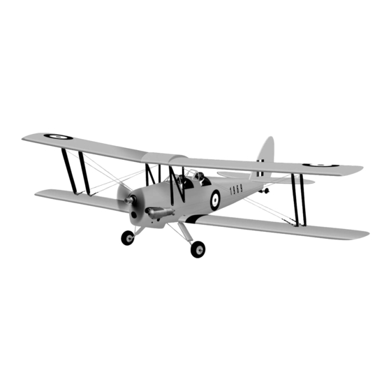
Phoenix Model TIGER MOTH Instruction Manual
Hide thumbs
Also See for TIGER MOTH:
- Instruction manual (17 pages) ,
- Instruction manual (41 pages) ,
- Instruction manuals (19 pages)
Table of Contents
Advertisement
Quick Links
Download this manual
See also:
Instruction Manual
I n s t r u c t i o n M a n u a l
SPECIFICATION
- Wingspan: 1404mm (55.3in)
- Length: 1134mm (44. 6 in)
- Flying weight: 3.2-3.4 kg
- Covering type: Genuine ORACOVER®
- Spinner size: scale type (not included)
- Radio: 4 channel minimum (not included)
- Servo: 2 aileron; 1 elevator; 1 rudder;
1 throttle (not included)
- Recommended receiver battery:
4.8-6V / 800-1200mAh NiMH (not included)
- Propeller: suit with your engine
- Engine: .46-.55 / 2-stroke or .52/4-stroke
glow engine (not included)
- Motor: brushless outrunner 1000-1400 W,
480 KV (not included)
- Gravity CG: 90 mm (3.5 in) Back from the
leading edge of the upper wing, at the fuselage
- Control throw Ailerons: Low: 10mm up/down,
10% expo; High: 12mm up/down, 10% expo
- Control throw Elevators: Low: 8mm up/down,
12% expo; High: 10mm up/down, 12% expo
- Control throw Rudder: Low: 25mm right/left,
15% expo; High: 40mm right/left, 15% expo
- Experience level: Intermediate
- Plane type: Scale Civilian
RECOMMENDED MOTOR AND BATTERY SET UP
- Motor: RIMFIRE .46-.55 (not included)
- Lipo cell: 6 cells / 4000 – 5500mAh (not included)
- Esc: 50-70A (not included)
Advertisement
Table of Contents

Related Manuals for Phoenix Model TIGER MOTH


Summary of Contents for Phoenix Model TIGER MOTH
- Page 1 I n s t r u c t i o n M a n u a l SPECIFICATION - Wingspan: 1404mm (55.3in) - Gravity CG: 90 mm (3.5 in) Back from the - Length: 1134mm (44. 6 in) leading edge of the upper wing, at the fuselage - Flying weight: 3.2-3.4 kg - Control throw Ailerons: Low: 10mm up/down, - Covering type: Genuine ORACOVER®...
-
Page 2: Tools And Supplies Needed
This will assure proper assembly. The TIGER MOTH .46-.55 SCALE 1:6 ¼ ARF is hand made from natural materials, every plane is unique and minor adjustments may have to be made. -
Page 3: Installing The Aileron Linkages
Instruction Manual TIGER MOTH 5. Place the aileron servo tray / hatch into the servo box on the bottom of the wing and drill 1,6mm pilot holes through the tray and the servo box for each of the four mounting screws. -
Page 4: Installing The Horizontal Stabilizer
Instruction Manual TIGER MOTH INSTALLING THE HORIZONTAL STABILIZER 1. Using a modeling knife, cut away the covering from the fuselage for the stabilizer and remove it. To the cowl Silicone Tube 9. Repeat step # 4 - # 8 to install the second Remove the covering aileron linkage. -
Page 5: Installing The Vertical Stabilizer
Instruction Manual TIGER MOTH 9. After the epoxy has fully cured, remove the masking tape or T-pins used to hold the stabilizer in place and carefully inspect the glue joints. Use more epoxy to fill in any gaps that were not filled previously and clean up the excess using a paper towel and rubbing alcohol. -
Page 6: Installing The Landing Gear
Instruction Manual TIGER MOTH 4. Prepare the tail gear as shown. 8. Secure the tail gear. 25mm 60mm Screw 5. Trim a channel and drill a hole onto the Rudder INSTALLING THE LANDING GEAR for tail gear as picture below. -
Page 7: Engine Installation
Instruction Manual TIGER MOTH 4. Attach and glue the plastic cover for the landing 110mm gear. Silicone glue C.A glue ENGINE INSTALLATION INSTALLING THE MOTOR AND BATTERY INSTALLING THE THROTTLE PUSHROD HOUSING Installing the electric motor 1. Install the engine mount into the fire wall using 4mm x 25mm screw. - Page 8 Instruction Manual TIGER MOTH FUEL TANK INSTALLING THE STOPPER ASSEMBLY Screw 1. The stopper has been pre-assembled at the factory. 2. Using a modeling knife, cut one length of silicon fuel line (the length of silicon fuel line is calculated by how the weighted clunk should rest about 8mm away from the rear of the tank and move freely inside the tank).
-
Page 9: Installing The Elevator Pushrod
Instruction Manual TIGER MOTH Blow through one of the lines to ensure the fuel lines have not become kinked inside the fuel Rudder servo Throttle servo tank compartment. Air should flow through easily. Do not secure the tank into place permanently until after balancing the airplane. -
Page 10: Installing The Rudder Pushrod
Instruction Manual TIGER MOTH INSTALLING THE RUDDER PUSHROD 7. Attach clevis to the third hole in the control horn. Install a silicone tube on the clevis. 1. Locate the pushrod exit slot on the left of the fuselage. 2. Carefully cut away the covering material from the slot. -
Page 11: Mounting The Cowl
Instruction Manual TIGER MOTH 12. Using a pliers, carefully make a 90 degree bend up at the mark made. Cut off excess wire, leaving about 8mm beyond the bend. 13. Insert the 90 degree bend up through the hole in the servo arm. Install one nylon snap keeper over the wire to secure it to the arm. -
Page 12: Installing The Wing
Instruction Manual TIGER MOTH 2. Cut out the switch hole using a modeling knife. Use a 2mm drill bit and drill out the two mounting holes through the fuselage side. 3. Secure the switch in place using the two machine screws provided with the radio system. - Page 13 Instruction Manual TIGER MOTH Screw 3. Install the metal strap to the lower wing as 5. Install two metal strap to the upper wing as picture below. picture below. Aluminum plate Screw Aluminum plate Screw 6. Install the wing strut as picture below.
- Page 14 Instruction Manual TIGER MOTH LOCATION OF WING STRUT Screw Front Wing strut Aluminum plate 7. Install the upper wing to the wing strut. Screw Metal strap 9. Install the cable. Short Metal strap Long Front 8. Install two wing strut to the both wing.
-
Page 15: Lateral Balance
Instruction Manual TIGER MOTH BALANCING 10. Install the cable. 1. It is critical that your airplane be balanced correctly. Improper balance will cause your plane to lose control and crash. THE CENTER OF GRAVITY IS LOCATED 90mm BACK FROM THE LEADING EDGE OF THE UPPER WING, AT THE FUSELAGE. -
Page 16: Control Throws
Instruction Manual TIGER MOTH CONTROL THROWS 1. We highly recommend setting up a plane using the control throws listed. 2. The control throws should be measured at the widest point of each control surface. 3. Check to be sure the control surfaces move in the correct directions.
Need help?
Do you have a question about the TIGER MOTH and is the answer not in the manual?
Questions and answers