Table of Contents
Advertisement
Quick Links
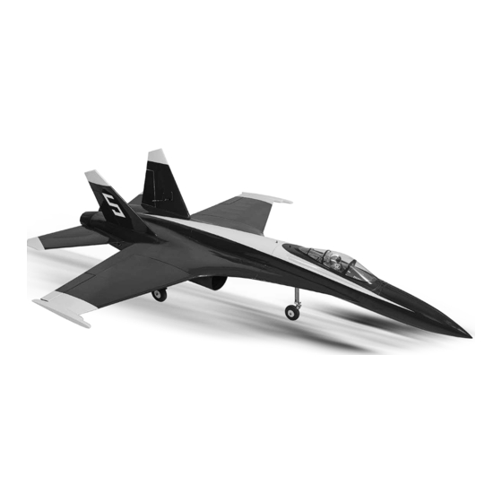
I n s t r u c t i o n M a n u a l
SPECIFICATION
- Wingspan: 1290mm (50.7 in)
- Length: 1778mm (70 in)
- Flying weight: 7000-7400 gr
- Wing area: 48 dm2
- Wing loading: 145g/dm2
- Wing type: Naca airfoils
- Covering type: Genuine ORACOVER®
- Retract gear type: Air retract gear with CNC
Suspension Metal Struts (included)
- Radio: 6 - 9 channel . 8 mini hi-torque servo
(Hitec HS5245MG): 2 aileron; 2 flap; 1 steering
nose; 1 retract valve ; 2 rudder ; 2 standard
hi-torque servo (minimum 9kg) for 2 elevator
(not included)
- Engine: edf 120mm (not included)
- Gravity CG: 95mm (3,8 in) Back from the
leading edge of the wing, at the fuselage
- Control throw Ailerons: Low: 7mm up/down,
10% expo; High: 10mm up/down, 10% expo
- Control throw Elevators: Low: 11mm up/down,
12% expo; High: 15mm up/down, 12% expo
- Control throw Rudder: Low: 10mm right/left,
15% expo; High: 20mm right/left, 15% expo
- Control throw flap : Mid : 15mm down;
Landing : 20mm down
- Experience level: advanced
RECOMMENDED EDF AND BATTERY SET UP
- EDF: 120mm, Minimum thrust 7 kg. As BVM 3-12S
EVF or Ramtec 120mm ...(not included)
- Lipo cell: 12 cells / 5000- 6000mAh 60C
(not included)
- Esc HV 160A Phoenix Casttle (not included)
Advertisement
Table of Contents

Related Manuals for Phoenix Model Thunder Streak


Summary of Contents for Phoenix Model Thunder Streak
- Page 1 I n s t r u c t i o n M a n u a l SPECIFICATION - Wingspan: 1290mm (50.7 in) - Control throw Ailerons: Low: 7mm up/down, - Length: 1778mm (70 in) 10% expo; High: 10mm up/down, 10% expo - Flying weight: 7000-7400 gr - Control throw Elevators: Low: 11mm up/down, - Wing area: 48 dm2...
-
Page 2: Tools And Supplies Needed
1. Please trial fit all the parts. Make sure you have the correct parts and that they fit and are aligned properly before gluing! This will assure proper assembly. The THUNDER STREAK EDF 120MM SCALE 1:6 ARF is hand made from natural materials, every plane is unique and minor adjustments may have to be made. -
Page 3: Installing The Control Horns
Instruction Manual THUNDER STREAK 3. Place the servo into the servo tray. Center the servo within the tray and drill 1,6mm pilot holes through the block of wood for each of the four To the cowl mounting screws provided with the servo. -
Page 4: Installing The Aileron Linkages
Instruction Manual THUNDER STREAK INSTALLING THE CONTROL HORNS for flap 4. Plug the aileron servo into the receiver and center the servo. Install the servo arm onto the servo. The servo arm should be perpendicular Repeat step #1 - #3 from installing the control... - Page 5 Instruction Manual THUNDER STREAK 4. Place the retract to the wing and pull out the air tube through the wing section. INSTALLING THE MAIN AIR RETRACT gear Air tube Trim the plastic wheel well 5. Secure the retract. Screw 2. Glue the plastic wheel well in place.
- Page 6 Instruction Manual THUNDER STREAK 8. Make the same way for the opposite gear retract. 4. Install the tube to the air retract. Screw INSTALLING THE NOSE AIR RETRACT gear 5. Secure the air retract. Trim the plastic wheel well Screw Trim 6.
- Page 7 Instruction Manual THUNDER STREAK 8. Slide and secure two cable rod to the nose gear. 2. The air valve. Crimp 9. Slide and secure two cable rod to the steering 3. Attach the air valve to the servo. arm servo.
-
Page 8: Installing The Landing Gear
Instruction Manual THUNDER STREAK INSTALLING THE LANDING GEAR SUPERLOCK AIR RETRACTS AIR SUPPLY VALUE ONE WAY MAIN GEAR 3 WAY CONNECTOR NOSE GEAR VALVE CONTROL 4 WAY CONNECTOR MAIN GEAR AIR TANK SERVO 4 WAY CONNECTOR INSTALLING THE HORIZONTAL STABILIZER 2. -
Page 9: Installing The Elevator Linkages
Instruction Manual THUNDER STREAK INSTALLING THE ELEVATOR LINKAGES Insert the carbon tube to the elevator and glue it by C.A glue. Make the same way from installing the aileron linkages for installing the elevator linkges. 40mm C.A glue Attach and secure the horizontal stabilizer to the fuselage using aluminum control horn. - Page 10 Instruction Manual THUNDER STREAK 6. Install and glue the rudder control horn. 2. Remove the covering. C.A glue Remove the covering Repeat these step from installing the aileron 3. Install the rudder servo. linkages to install the rudder linkages. Screw 4.
- Page 11 Instruction Manual THUNDER STREAK 2. Trim 1 hole from the air outlet for the wires of EDF. Slide the extension servo lead through the fuselage. Install the vertical stabilizer and glue it using epoxy glue. Servo lead Remove the covering 3.
- Page 12 Instruction Manual THUNDER STREAK 6. Slide and fix the air outlet. 8. Glue the wooden belt to the air inlet. C.A glue Wooden belt 9. Trim the plastic inlet lip. C.A glue 10. Glue the plastic inlet lip to the fuselage using C.A glue.
- Page 13 Instruction Manual THUNDER STREAK OPEN AND CLOSE the canopy 11. Cut the hole on the fuselage for installing the air cooling exhaust plastic. Remove the Open and Close covering BALANCING 12. Glue the air cooling exhaust plastic by C.A glue.
-
Page 14: Lateral Balance
Instruction Manual THUNDER STREAK LATERAL BALANCE LOW RATE After you have balanced a plane on the C.G. Ailerons : 7mm up 7mm down You should laterally balance it. Doing this will Elevator : 11mm up 11mm down help the airplane track straighter. - Page 15 I/C FLIGHT WARNINGS Always operate in open areas, away Keep all onlookers (especially small from factories, hospitals, schools, THE PROPELLER IS DANGEROUS children and animals) well back from buildings and houses etc. NEVER fly Keep fingers, clothing (ties, shirt the area of operation. This is a flying your aircraft close to people or built sleeves, scarves) or any other loose aircraft, which will cause serious...
- Page 16 I/C FLIGHT GUIDELINES Operate the control sticks on the When ready to fly, first extend the transmitter and check that the control transmitter aerial. surfaces move freely and in the ALWAYS land the model INTO the CORRECT directions. wind, this ensures that the model lands at the slowest possible speed.
Need help?
Do you have a question about the Thunder Streak and is the answer not in the manual?
Questions and answers