Table of Contents
Advertisement
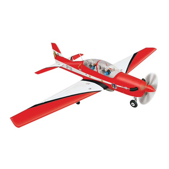
SPECIFICATION
- Wingspan: 1578mm (62.1in)
- Length: 1359mm (53.5 in)
- Flying weight: 2.9-3.2 kg
- Wing area: 39.4 dm2
- Wing loading: 80g/dm2
- Wing type: Naca airfoils
- Covering type: Genuine ORACOVER®
- Gear type: Wire main gear and CNC
Suspension Metal Struts nose gear (included)
- Spinner size: Plastic 58mm (included)
- Radio: 4 channel minimum (not included)
- Servo: 5 standard servo: 2 aileron; 1 elevator;
1 rudder; 1 throttle (not included)
- Recommended receiver battery:
4.8-6V / 800-1200mAh NiMH (not included)
- Servo mount: 21mm x 42 mm
- Propeller: suit with your engine
Instruction Manual
- Engine: .46-.55 / 2-stroke or .52/4-stroke
glow engine (not included)
- Motor: brushless outrunner 1000-1400 W,
480 KV (not included)
- Gravity CG: 85-90 mm (3.5 in) Back from
the leading edge of the wing, at the fuselage
- Control throw Ailerons: Low: 8mm up/down,
10% expo; High: 10mm up/down, 10% expo
- Control throw Elevators: Low: 8mm up/down,
12% expo; High: 10mm up/down, 12% expo
- Control throw Rudder: Low: 25mm right/left,
15% expo; High: 40mm right/left, 15% expo
- Experience level: Intermediate
- Plane type: Scale Military
RECOMMENDED MOTOR AND BATTERY SET UP
- Motor: RIMFIRE .46-.55 (not included)
- Lipo cell: 6 cells / 4000 – 5500mAh (not included)
- Esc: 50-80A (not included)
Advertisement
Table of Contents

Related Manuals for Phoenix Model TUCANO


Summary of Contents for Phoenix Model TUCANO
-
Page 1: Instruction Manual
Instruction Manual SPECIFICATION - Engine: .46-.55 / 2-stroke or .52/4-stroke - Wingspan: 1578mm (62.1in) glow engine (not included) - Length: 1359mm (53.5 in) - Motor: brushless outrunner 1000-1400 W, - Flying weight: 2.9-3.2 kg 480 KV (not included) - Wing area: 39.4 dm2 - Gravity CG: 85-90 mm (3.5 in) Back from - Wing loading: 80g/dm2 the leading edge of the wing, at the fuselage... -
Page 2: Safety Precaution
This will assure proper assembly. The TUCANO 40 is hand made from natural materials, every plane is unique and minor adjustments may have to be made. However, you should find the fit superior and assembly simple. -
Page 3: Installing The Control Horns
To the cowl Remove the covering 3. Place the servo into the servo tray. Center the servo within the tray and drill 1,6mm pilot holes through the block of wood for each of the four mounting screws provided with the servo. To the cowl INSTALLING THE CONTROL HORNS 1. -
Page 4: Installing The Aileron Linkages
INSTALLING THE AILERON LINKAGES 8. Insert the 90 degree bend down through the hole in the servo arm. Install one nylon snap keeper over the wire to secure it to the arm. 1. Working with the aileron linkage for now, thread Install the servo arm retaining screw and one nylon clevis at least 14 turns onto one of remove the masking tape from the aileron. -
Page 5: Vertical Stabilizer Installation
Glue with epoxy Glue with C.A glue 7. After the epoxy has fully cured, remove the masking tape or T-pins used to hold the stabilizer in place and carefully inspect the glue joints. Use more epoxy to fill in any gaps that were not filled previously and clean up the excess using a paper towel and rubbing alcohol. -
Page 6: Installing The Landing Gear
INSTALLING THE landing gear without the retractable gear) 1. Install the landing gear ( included with the kit) to the wooden block. 4. Now, remove the vertical stabilizer and using a modeling knife, carefully cut just inside the marked lines and remove the film on both sides Screw of the vertical stabilizer. -
Page 7: Installing The Nose Gear
5. Install two of the wheels onto the axles using the four wheel collars and set screws provided. The FIGURE #4 wheels should be centered on the axles with a wheel collar on each side, holding them in STREERING place. Tighten the set screws on the collars to secure them in place.The wheels should rotate freely. - Page 8 ASSEMBLE and install RETRACT GEAR SYSTEM (Retract gear is not included in the kit, must be buy separately) INSTALLING THE retract nose gear 5. Grind flat spot at the landing gear. 1. Remove the wood on the fuselage for installing the nose gear.
- Page 9 11. Install the nose pushrod into the rudder servo arm. 9. Retract and the gear is opened. Rudder servo Metal pushrod Steering arm Nose gear arm M2 Clevis INSTALLING THE landing gear 1. Remove the covering. 10. Retract and the gear is closed. Remove the covering 2.
- Page 10 3. Glue the “C” wood part to the wing. 7. Attach the metal rod to the retract gear. 75mm Metal pushrod Clevis 4. Trim the plastic cover. 8. Install and secure the retract gear into the wing. Remove the covering 5.
-
Page 11: Installing The Engine
11. Secure the wheel. 14. Retract and the gear is closed. 12. Install the adjustable servo connector to the servo arm of the servo retract gear. 13. Retract and the gear is opened. INSTALLING THE ENGINE Locate the long piece of wire used for the throttle pushrod. -
Page 12: Installing The Motor And Battery
INSTALLING THE MOTOR AND BATTERY Installing the electric motor This model can fly with electric, here is our recommended for set up the system. - Motor brushless: Rimfire .46 - .55 - Lipo cells: 6 cells / 4000 - 5000 mAh. - ESC: 50A - 70A. -
Page 13: Installing The Stopper Assembly
FUEL TANK installation Do not secure the tank into place permanently until after balancing the airplane. You may need to remove the tank to mount the battery in INSTALLING THE STOPPER ASSEMBLY the fuel tank compartment. 1. The stopper has been pre-assembled at the factory. 9. -
Page 14: Installing The Elevator Pushrod
INSTALLING THE ELEVATOR PUSHROD 10.Plug the elevator servo into the receiver and center the servo. Install the servo arm onto the servo. The servo arm should be perpendicular 1. Locate the pushrod exit slot on the right side to the servo and point toward the middle of the and left side of the fuselage. -
Page 15: Installing The Throttle
INSTALLING THE STEERING PUSHROD 4. Install the clevis on the rudder pushrod. Make sure 6mm of thread shows inside the clevis. 1. Install an adjustable servo connector in to the 5. The control horn should be mounted on the rudder servo arm as the photo below. right side of the rudder at the leading edge, in line with the rudder pushrod. -
Page 16: Mounting The Cowl
4. Manually push the carburator barrel fully closed. Angle the arm back about 45 degree from center and attach the servo arm onto the servo. With the carburator barrel fully closed, tighte the set screw in the adjustable metal connector. 5. -
Page 17: Installing The Switch
installing the plastic bomb 3. Position the battery pack and receiver behind the fuel tank. Use the two light plywood pieces, placed over the battery and receiver and glue to the fuselage sides to hold the battery and receiver securely in place. Use 15mm triangle pieces glued between the fuselage sides and the plywood pieces to reinforce the joints. -
Page 18: Lateral Balance
4. If the nose of the plane falls, the plane is heavy nose. To correct this first move the battery pack further back in the fuselage. If this is not possible or does not correct it, stick small amounts of lead weight on the fuselage under Aileron Control the horizontal stabilizer. -
Page 19: Metric Conversions
I/C FLIGHT WARNINGS Always operate in open areas, away Keep all onlookers (especially small from factories, hospitals, schools, THE PROPELLER IS DANGEROUS children and animals) well back from buildings and houses etc. NEVER fly Keep fingers, clothing (ties, shirt the area of operation. This is a flying your aircraft close to people or built sleeves, scarves) or any other loose aircraft, which will cause serious... - Page 20 I/C FLIGHT GUIDELINES Operate the control sticks on the When ready to fly, first extend the transmitter and check that the control transmitter aerial. surfaces move freely and in the ALWAYS land the model INTO the CORRECT directions. wind, this ensures that the model lands at the slowest possible speed.
Need help?
Do you have a question about the TUCANO and is the answer not in the manual?
Questions and answers