Table of Contents
Advertisement
Quick Links
Advertisement
Table of Contents

Related Manuals for Phoenix Model Diabolo


Summary of Contents for Phoenix Model Diabolo
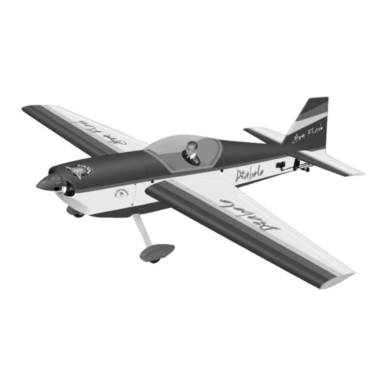
- Page 1 : 3200 gr (7 lbs) Engine : 60 two stroke Radio : 4 - 9 channel / 6 servos We wish you many enjoyable flights with your plane and one again thank you for your choosing a Phoenix Model products.
-
Page 2: Kit Contents
Instruction Manual Diabolo KIT CONTENTS: We have organized the parts as they come out of the box for better identification during assembly. We recommend that you regroup the parts in the same manner. This will ensure you have all of parts required before you begin assembly. -
Page 3: Tools And Supplies Needed
2. Turn the wing panel right side up. Using a modeling before gluing! This will assure proper assembly. The knife, remove the covering from over the precut DIABOLO ARF is hand made from natural materials, servo box. every plane is unique and minor adjustments may have to be made. -
Page 4: Installing The Control Horns
Instruction Manual Diabolo 4. Using the thread as a guide and using masking tape, INSTALLING THE CONTROL HORNS tape the servo lead to the end of the thread: carefully pull the thread out. When you have pulled the servo 1. The aileron has a block wood plate for mounting lead out, remove the masking tape and the servo lead the control horn. -
Page 5: Installing The Aileron Linkages
Instruction Manual Diabolo INSTALLING THE AILERON LINKAGES 4. Center the aileron and hold it in place using a couple of pieces of masking tape. Adjust the The aileron linkages are assembled as shown below linkage until the aileron and the servo arm are both centered and then tighten the nut against the clevis. - Page 6 Instruction Manual Diabolo 2. Draw a center line onto the horizontal stabilizer. 6. Attach the wing to the fuselage as picture. Plastic screw Center line Picture 15 Picture 18 3. Check the fit of the horizontal stabilizer in its slot. Make sure the horizontal stabilizer is square and centered to the fuselage by taking 7.
-
Page 7: Vertical Stabilizer Installation
Instruction Manual Diabolo 9. After the epoxy has fully cured, remove the 4. Slide the vertical stabilizer back in place. Using triangle, check to ensure that the vertical masking tape or T-pins used to hold the stabilizer is aligned 90 degree to the horizontal stabilizer in place and carefully inspect the glue stabilizer. -
Page 8: Installing The Wheel Pants
Instruction Manual Diabolo 1. Set the tail wheel assembly in place on the plywood plate. 2. Drill 2,6mm pilot holes through the plywood plate. 3. Secure the tail wheel bracket in place using two Drill 3mm x 12mm screw. 4. Align the tail wheel wire so that the wire is parallel with the bottom of the rudder. -
Page 9: Installing The Main Landing Gear
Instruction Manual Diabolo INSTALLING THE ENGINE After installing the wheel pant, apply a small drop of thin C/A to the bottom nut. • Locate the long piece of wire used for the throttle pushrod. One end of the wire has been 9. -
Page 10: Servo Installation Installing The Fuselage Servos
Instruction Manual Diabolo SERVO INSTALLATION INSTALLING THE FUSELAGE SERVOS 1. Install the rubber grommets and brass collets into the elevator, rudder and throttle servos. Test fit the servos into the servo tray. Trim the tray if necessary to fit your servos 2. -
Page 11: Installing The Rudder Servo
Instruction Manual Diabolo INSTALLING THE RUDDER SERVO 1. Remove the covering from the left size of the fuselage. 2. Install servo to the fuselage as shown. Picture 33 INSTALLING THE ELEVATOR LINKAGES . Repeat these step as installing the aileron linkages ( Page 4 and page 5 ) . -
Page 12: Mounting The Cowl
Instruction Manual Diabolo MOUNTING THE COWL 1. Remove the muffler and needle valve assembly from the engine. Slide the fiberglass cowl over the engine. 2. Measure and mark the locations to be cut out for engine head clearance, needle valve, muffler,. -
Page 13: Final Assembly
Instruction Manual Diabolo INSTALLING THE CANOPY BALANCING • Remove the covering from four holes on the 1. It is critical that your airplane be balanced correctly. Improper balance will cause your fuselalage and then install the canopy by 4mm plane to lose control and crash. -
Page 14: Control Throws
Rudder : 30mm right 30mm left 6. Properly balance the propeller. We wish you many enjoyable flights with 12mm your plane and once again thank you for 12mm your choosing a Phoenix Model's product. Aileron Control 16mm 16mm Elevator Control 30mm... - Page 15 Instruction Manual Diabolo I/C FLIGHT WARNINGS...
- Page 16 I/C FLIGHT GUIDELINES Operate the control sticks on the When ready to fly, first extend the transmitter and check that the control transmitter aerial. surfaces move freely and in the ALWAYS land the model INTO the CORRECT directions. wind, this ensures that the model lands at the slowest possible speed.
Need help?
Do you have a question about the Diabolo and is the answer not in the manual?
Questions and answers