Table of Contents

Related Manuals for RayTek Raynger Series 3i Plus


Summary of Contents for RayTek Raynger Series 3i Plus
-
Page 1: Operating Instructions
Raynger Series ® 3i Plus Handheld Infrared Thermometer Operating Instructions Rev. A1 Jan 2015 4557194 Sensorik Messtechnik A-8010 Graz, Riesstraße 146 Tel.: +43 316 40 28 05, Fax: 40 25 06 H a n d e l s g e s e l l s c h a f t m . b . H . - Page 2 Thank you for purchasing this Raytek product. Register today at www.raytek.com/register to receive the latest updates, enhancements and software upgrades! © Raytek Corporation Raytek and the Raytek Logo are registered trademarks of Raytek Corporation. All rights reserved. Specifications subject to change without notice.
- Page 3 ARRANTY The manufacturer warrants this instrument to be free from defects in material and workmanship under normal use and service for the period of one year from date of purchase. This warranty extends only to the original purchaser. This warranty shall not apply to fuses, batteries, or any product that has been subject to misuse, neglect, accident, or abnormal conditions of operation.
-
Page 4: Table Of Contents
Content CONTENT ................................4 1 SAFETY INSTRUCTIONS ..........................6 2 PRODUCT DESCRIPTION .......................... 11 2.1 F ..............................12 EATURES 3 TECHNICAL DATA ............................13 3.1 M ....................... 13 EASUREMENT PECIFICATIONS 3.2 O ............................14 PTICAL HARTS 3.3 G ......................... 14 ENERAL PECIFICATIONS 3.4 E... - Page 5 5.10.12 °C and °F ............................30 5.10.13 Scope ..............................30 5.11 D ........................... 30 OWNLOAD 6 ACCESSORIES ..............................31 7 WINDOWS SOFTWARE ..........................32 7.1 I ............................32 NTRODUCTION 7.2 S ..........................33 YSTEM EQUIREMENTS 7.3 S ........................33 OFTWARE NSTALLATION 7.4 C ............................
-
Page 6: Safety Instructions
Safety Instructions 1 Safety Instructions This document contains important information, which should be kept at all times with the instrument during its operational life. Other users of this instrument should be given these instructions. Eventual updates to this information must be added to the original document. The instrument can only be operated by trained personnel in accordance with these instructions and local safety regulations. - Page 7 Safety Instructions Safety Symbols Risk of danger. Important information. See manual. Hazardous voltage. Risk of electrical shock. Warning Laser. Helpful information regarding the optimal use of the instrument. °C Celsius °F Fahrenheit Lithium-Ion Battery Li-ion This product complies with the WEEE Directive (2002/96/EC) marking requirements.
- Page 8 Safety Instructions Class A digital device: This equipment has been tested and found to comply with the limits for a Class A digital device, pursuant to Part 15 of the FCC Rules. These limits are designed to provide reasonable protection against harmful interference when the equipment is operated in a commercial environment.
- Page 9 Safety Instructions Warnings A warning identifies conditions and procedures that are dangerous to the user. To prevent possible electrical shock, fire, or personal injury follow these guidelines: • Read all safety information before you use the product. Use the product only as specified, or the protection supplied by the product can be •...
- Page 10 Safety Instructions Battery Warning The battery is a safety device. Do not attempt to disassemble or alter the battery. Always observe the following precautions: • Do not short-circuit the battery by directly connecting the negative terminals with positive terminal. • Do not heat the battery or discard it in a fire.
-
Page 11: Product Description
Product Description 2 Product Description The Raynger 3i Plus Series of instruments are portable infrared temperature measurement devices. Each model is rugged and easy to use for making fast, noncontact, nondestructive temperature measurements. They can measure product temperatures during manufacturing or storage without contaminating or marring the product. -
Page 12: Features
Product Description 2.1 Features The Raynger 3i Plus Series has the following features: • Dual laser sighting • Current temperature plus MAX, MIN, DIF, AVG temperatures • Audible/visual alarms for target temperature, ambient temperature, and low battery • Adjustable emissivity and predefined emissivity table •... -
Page 13: Technical Data
Technical Data 3 Technical Data 3.1 Measurement Specifications Temperature Range 700 to 3000°C (1292 to 5432°F) 400 to 2000°C (752 to 3632°F) Spectral Response 1.0 µm 1.6 µm Optical Resolution D:S All models 250:1 16 mm spot @ 4000 mm distance (0.63 in @ 157 in) System Accuracy ±... -
Page 14: Optical Charts
Technical Data 3.2 Optical Charts Figure 2: Spot Size Charts 3.3 General Specifications Operating Temperature 0 to 50°C (32 to 122°F) Storage Temperature -20 to 60°C (-4°F to 140°F) without battery Operating Humidity 10 to 90% RH, not condensing at 30°C (86°F) Environmental Rating IP40 (NEMA 1) Drop Performance... -
Page 15: Electrical Specifications
Technical Data Weight Standard 700 g (25 oz) with scope 950 g (34 oz) Display Illuminated backlight display (On/Off, white color, orange color) display Hold (20 s) Laser Dual laser (EN60825 Class 2, FDA Class II) 3.4 Electrical Specifications Power Supply Battery or USB Battery Lithium-ion, single cell, 3.6 V, 2500 mAh... -
Page 16: Basics
Basics 4 Basics 4.1 Measurement of Infrared Temperature All objects emit an amount of infrared radiation according to their surface temperature. The intensity of the infrared radiation changes according to the temperature of the object. Depending on the material and surface properties, the emitted radiation lies in a wavelength spectrum of approximately 1 to 20 µm. -
Page 17: Operation
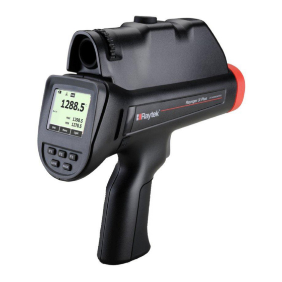
Operation 5 Operation 5.1 Quick Start To use the instrument right away, complete the following steps: Point the instrument at the object the user wants to measure (as perpendicular as possible to the object) and pull the trigger. The current temperature (in °C or °F), emissivity value, and maximum and minimum measured temperature are displayed. -
Page 18: Distance And Spot Size
Operation Nose with Temperature Scope Adjustable Screw Sensor inside Polaroid Frame Red Dot Scope 2 Laser Aperture Tripod Screw 3x Soft Keys Trigger Save Key Return Key USB Interface Battery Cover and Screw Figure 3: Portable Thermometer with Scope The portable thermometer has the following: Trigger: One-stage trigger, which activates the unit to take temperature readings. -
Page 19: High Temperature Nose
Operation Figure 4: Field of View For accurate measurements the target size must be at least two times bigger than the Spot diameter 5.4 High Temperature Nose The instrument has a specially designed nose with high temperature resistant plastic material to avoid damage from high temperature targets. -
Page 20: Display
Operation 5.6 Display The display retains the last infrared measurement for 20 s when the trigger is released and <HOLD> is shown on the display. To hold the infrared temperature, release the trigger until <HOLD> shows on the display. 5.7 Sighting 5.7.1 Dual Laser All models use a dual laser method to show the measurement spot position and size. -
Page 21: Save Button
Operation down arrows to select each saved trend data. The user can then use left and right arrows to view the three screens for each piece of trend data. Profile test data: Profile setting under which 300 test data records (maximum) are saved. •... - Page 22 Operation ② ③ ④ ⑤ ⑥ ① ⑦ ⑭ ⑬ ⑫ ⑧ ⑪ ⑩ ⑨ Figure 5: User Interface Number Description Number Description ① ⑧ Battery Symbol Max. Value Display ② ⑨ Laser Indicator Min. Value Display ③ ⑩ Scan/Hold Background Temp.
-
Page 23: Ems - Emissivity
Operation Level <F1> Description <F2> <F3> Description Sets the emissivity value Menu Light Toggles the LCD backlit Profile Calls predefined profiles Menu Trend Reviews recorded trends MnMx Enables minimum/maximum Menu Enables average/difference Lock/Unlock Locks/unlocks the trigger button Menu Laser Toggles the laser Time/Date, Alarm, Transmissivity, Review/Delete recorded Setup... - Page 24 Operation characters (combination of number and letter), and the third level can be defined by a sequential test point number. The user can define the unique structure to meet complicated needs. The following example can be regarded as a sequential structure: •...
-
Page 25: Trend
Operation Choose the <Next> button, and the user can select location number and use various preset parameters to perform test. In the following example, selecting profile code WGA ECA location number 98 has a setting of: High -temperature Alarm HI = 2120 Low -temperature Alarm LO = 1836 Emissivity ε... -
Page 26: Mnmx - Minimum, Maximum
Operation The instrument will save three pages of curves when the user presses <Save>. The maximum record in trend mode is 10 pcs curve; each curve can be displayed in three pages. The figure below is under trend auto mode. The data show on Y-axes is automatically displayed using the maximum and minimum value in the record period. -
Page 27: Laser
Operation Push the <Menu> soft key until the lock symbol shows as the left soft key function. Push the soft key to lock the trigger. The lock symbol is shown on the display to designate a locked trigger. When the trigger is locked, the soft key changes to unlock. Push this soft key to unlock the trigger. -
Page 28: Alarm
Operation 10. Push the <Next> soft key to move through each parameter. 11. Push the <Done> soft key when finished. The display reverts to the start of the <Time/Date> menu. 5.10.10.2 Alarm The instrument has a programmable alarm to designate high or low readings, depending on the thresholds entered. -
Page 29: To Default
Operation 5.10.10.7 To Default To restore the instrument to the original factory default settings, press the <To Default> soft key. The following table provides the values in case of a factory default. Parameter Factory Default White Backlight Orange Backlight Scope Laser Buzzer Date... -
Page 30: C And °F
7.0 and above. After activating Bluetooth on the instrument, the user can find it on the iPhone. Use the “Raytek 3i Plus” App, which can be downloaded from the App Store (please search by its name). To monitor real-time measurement in a relative faraway place, download the Basic test data and Profile test data, take photos and send via e-mail. -
Page 31: Accessories
Accessories 6 Accessories Accessories include items that may be ordered at any time and added on-site: Carrying case (XXXR3IPLUSCC) • Neck strap (XXXR3IPLUSSTRAP) • CD with software for real-time graphic temperature display and data download • Lithium-ion battery, 2.5 Ah (XXXR3IPLUSACCU) •... -
Page 32: Windows Software
Windows Software 7 Windows Software 7.1 Introduction The DataTemp Raynger 3i Plus is the PC software application for Raynger 3i Plus series instruments. ® With this software, the user can perform real-time monitoring, download test data, and create profiles to optimize measurement. DataTemp Raynger 3i Plus software features: Displays acquired results in graphs and tables •... -
Page 33: System Requirements
Windows Software Description Real -time Monitor tab Basic Test Data tab Trend Test Data tab Profile create, edit, upload and Profile Test Data tab Start Measuring button End Measuring button Start Recording button Pause Recording button Setting button updates the instrument setting through the PC. Table area shows test data in record list. -
Page 34: Communication
Windows Software 7.4 Communication To establish communication between the instrument and the PC software, follow the steps below: Step 1: Connect the instrument to the PC via USB Step 2: Open the <File> menu Figure 7: Open File Step 3: Choose appropriate COM Port with Raynger 3i Plus Device and click <Connect> Figure 8: COM Port Selection 3i Plus Rev. - Page 35 Windows Software A simultaneous communication via USB and Bluetooth is not allowed! 3i Plus Rev. A1 Jan 2015...
-
Page 36: Real-Time Data
Windows Software 7.5 Real-Time Data 7.5.1 Display Under the real-time mode, the software provides multiple views. After pressing <Start Recording>, you can enter real-time monitor mode, the trigger of the instrument is locked automatically. The record list and the graph display will keep recording all test results until you press <Pause Recording>. -
Page 37: Replay
Windows Software Figure 10: Settings Dialog The user can change the following settings: Time Span Emissivity Transmittance Compensation Parameters (%) Transmittance Compensation Enabled Background Compensation Parameters Background Compensation Enabled High Alarm Temperature High Alarm Enabled Low Alarm Temperature Low Alarm Enabled Unit 7.5.3 Replay The user can replay the file recorded in real-time mode, search it according to date, and open the file... - Page 38 Windows Software Figure 11: Replay Window 3i Plus Rev. A1 Jan 2015...
-
Page 39: Recorded Data
Windows Software 7.6 Recorded Data The recorded data is divided into three groups: <Basic test data>, <Trend data>, and<Profile test data>. <Basic test data> is the test data without dedicated settings. The user can record random • measurement data in this area with a maximum of 1,000 records. <Trend data>... -
Page 40: Trend Data
Windows Software Figure 13: Data Deletion 7.6.2 Trend Data After the user has imported the trend test data from the instrument, the data will appear in a table formatted with the point# and corresponding temperature value. There is also a graphical area to display the trend data. Figure 14: Trend Data 7.6.3 Profile Data This feature provides a convenient method for the user to create settings through this function... -
Page 41: Local
Windows Software Figure 15: Profile Data 7.6.3.1 Local Under this mode, in <Local> the user can create their own setting group with three level menus and also with EMS, transmittance compensation, background compensation, high-temperature alarm, low- temperature alarm setting, and laser and backlight enable or disable. For each profile, it will have a profile code that includes the names of the first level menu, second level menu and test point number. -
Page 42: Device
Windows Software Figure 16: Local Profile Before measurement, the user can call up this profile in the instrument: 7.6.3.2 Device In <Device> mode, the user can download the existing profile from the instrument to the PC. Put the mouse cursor on the 2 level profile name, then click <Show Device Data>, afterwards all test data can be found in this place, click <Import to Local>... - Page 43 Windows Software Figure 17: Device Profile The user can also download the test data with the <Export> function into a csv format. Figure 18: Export Data to the PC 3i Plus Rev. A1 Jan 2015...
- Page 44 Windows Software The csv file will include the historical record of the same test points which is useful to the user to find the change rule of each point. For example, in the table below, test point 1 and test point 2 all have 5 records with different times and the data shows the temperature is stable on these days.
-
Page 45: Mobile App
Mobile App 8 Mobile App The “Raytek 3i Plus” mobile app is a computer program designed to run on smartphones, tablet computers and other mobile devices. The app requires the support of the iOS mobile operating system 7.0 or higher. -
Page 46: Basic Test Data
Mobile App Figure 21: Real-Time Temperature View By clicking on the camera icon on the upper-right corner, the user can take a photo from the field. By clicking on the <Send> icon, the user could e-mail the photo and data. Figure 22: Real-Time E-Mail 8.2 Basic Test Data By clicking on the <Basic Test Data>... -
Page 47: Data Review
Mobile App To ensure the download process more smooth, please do not use the unit perform testing during data download period. Figure 23: Basic Test Data Download 8.2.1 Data Review After completing the download, a list of the recorded dates and times will be displayed, see left figure below. -
Page 48: Data Review By Time
Mobile App Figure 25: Basic Log E-Mail Sending For sending multiple sets of data via e-mail, click on the to the left of the list of items, see left figure below. By clicking the e-mail icon in the upper right corner the selected test data can be sent, see right figure below. - Page 49 Mobile App Figure 27: Basic Log – Data Sets at the desired Starting Time By clicking on the time input box in the upper right corner, a dialog box opens to select the end time/data for the recorded data sets. Figure 28: Basic Log –...
-
Page 50: Profile Test Data
Mobile App Figure 29: Basic Log Download – Selected Data Items By clicking on the e-mail icon in the upper right corner, the selected data can be sent by e-mail. Figure 30: Basic Log Data E-Mail 8.3 Profile Test Data By selecting the <Profile Test Data>... - Page 51 Mobile App Figure 31: Profile Log Data For sending multiple sets of data, such as<A01 B01>, click the on the left side of the list of items, see left figure below. By clicking on the e-mail icon in the upper right corner the selected test data can be sent, see right figure below.
- Page 52 Mobile App Figure 33: Profile Test Data with Photos Attached 3i Plus Rev. A1 Jan 2015...
-
Page 53: Maintenance
Maintenance 9 Maintenance Our sales and customer service representatives are always at your disposal for questions regarding applications, calibration, repair, and solutions to specific problems. Please contact your local sales representative if you need assistance. In many cases, problems can be solved over the telephone. If you need to return equipment for servicing, calibration, or repair, please contact our Service Department before shipping. -
Page 54: Lens Cleaning
Maintenance 9.2 Lens Cleaning The user should periodically clean the instrument’s front window. A dirty front window (lens) can cause temperature measurement errors. The window is fragile, and care should be taken when cleaning it to prevent scratching. Use camera lens or eye glass tissues to clean the window. -
Page 55: Battery Exchange
Maintenance 9.5 Battery Exchange For exchanging the battery, follow the steps given below. 1. Unscrew the battery door. 2. Remove the battery door bolt. 3. Slide the battery along the lead rail. Figure 34: Removing the Battery 3i Plus Rev. A1 Jan 2015... -
Page 56: Appendix
Appendix 10 Appendix 10.1 Determination of Emissivity Emissivity is a measure of an object’s ability to absorb and emit infrared energy. It can have a value between 0 and 1.0. For example, a mirror has an emissivity of 0.1, while the so-called “Blackbody“ reaches an emissivity value of 1.0. - Page 57 Appendix Metals Emissivity Material 1 µm 1.6 µm Aluminum Unoxidized 0.1-0.2 0.02-0.2 Oxidized Alloy A3003, Oxidized Roughened 0.2-0.8 0.2-0.6 Polished 0.1-0.2 0.02-0.1 Brass Polished 0.1-0.3 0.01-0.05 Burnished Oxidized Chromium Oxidized Copper Polished 0.03 Roughened 0.05-0.2 Oxidized 0.2-0.8 0.2-0.9 Gold 0.01-0.1 Haynes Alloy 0.5-0.9...
- Page 58 Appendix Metals Emissivity Material 1 µm 1.6 µm Monel (Ni-Cu) 0.2-0.6 Oxidized Nickel Oxidized 0.8-0.9 0.4-0.7 Electrolytic 0.2-0.4 0.1-0.3 Platinum Black 0.95 Silver 0.02 Steel Cold-Rolled 0.8-0.9 0.8-0.9 Ground Sheet Polished Sheet 0.35 0.25 Molten 0.35 0.25-0.4 Oxidized 0.8-0.9 0.8-0.9 Stainless 0.35 0.2-0.9...
-
Page 59: Compliance Standards
Appendix 10.3 Compliance Standards IEC 61010-1 Safety Requirements for Electrical Equipment for Measurement, Control, and Laboratory Use -- Part1: General Requirements IEC 60529 Degrees of Protection Provided by Enclosures (IP Code) EN 61326-1 Electrical Equipment for Measurement, Control and Laboratory Use – EMC Requirements --- Part1 : General Requirements EN 61326-2-2 Electrical Equipment for Measurement, Control and Laboratory Use...
Need help?
Do you have a question about the Raynger Series 3i Plus and is the answer not in the manual?
Questions and answers