
Related Manuals for RayTek MARATHON MR


Summary of Contents for RayTek MARATHON MR
-
Page 1: Operating Instructions
ARATHON 2-Color Infrared Thermometer Operating Instructions Rev. E2 04/2011 56913... - Page 3 Thank you for purchasing this Raytek product. Register today at www.raytek.com/register to receive the latest updates, enhancements and software upgrades! © Raytek Corporation. Raytek, DataTemp and the Raytek Logo are registered trademarks of Raytek Corporation. All rights reserved. Specifications subject to change without notice.
- Page 4 ARRANTY The manufacturer warrants this instrument to be free from defects in material and workmanship under normal use and service for the period of two years from date of purchase. This warranty extends only to the original purchaser. This warranty shall not apply to fuses, batteries, or any product that has been subject to misuse, neglect, accident, or abnormal conditions of operation.
-
Page 5: Table Of Contents
ABLE OF ONTENTS 1 SAFETY INSTRUCTIONS ..........................7 2 PRODUCT DESCRIPTION ..........................8 2.1 T ..................9 HEORY OF PERATION FOR OLOR ENSORS 2.1.1 Partially Obscured Targets ........................9 2.1.2 Targets Smaller Than Field of View ...................... 9 2.1.3 Low or Changing Emissivities ......................10 3 TECHNICAL DATA ............................ - Page 6 6.3 I ..........................36 NPUTS AND UTPUTS 6.3.1 Milliamp Output ..........................36 6.3.2 Relay Outputs ............................ 36 6.3.3 Trigger ..............................36 6.4 F ..........................37 ACTORY EFAULTS 7 OPTIONS ................................. 38 7.1 W ..............38 ATER OOLED OUSING INCLUDING URGE OLLAR 8 ACCESSORIES ...............................
-
Page 7: Safety Instructions
Incorrect use of 110 / 230 V electrical systems can result in electrical hazards and personal injury. All instrument parts supplied with electricity must be covered to prevent physical contact and other hazards at all times. Marathon MR Rev. E2 04/2011... -
Page 8: Product Description
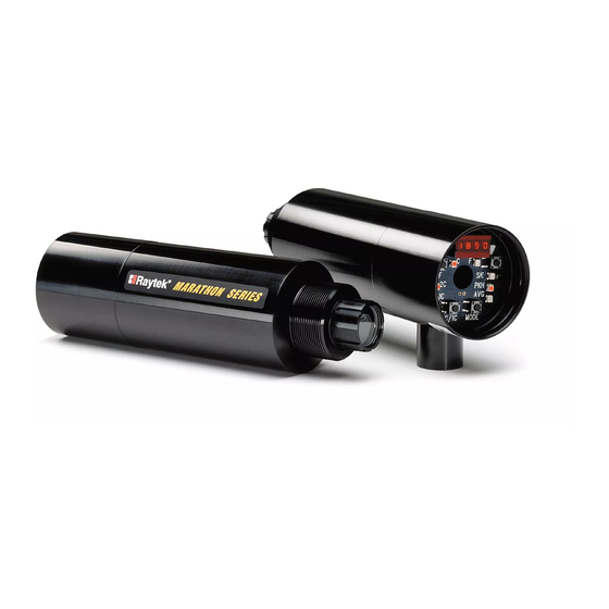
Product Description The Marathon MR Series of instruments are 2-color infrared noncontact temperature measurement systems with variable focus, through-the-lens sighting, and parallax-free optics. They are energy transducers designed to measure accurately and repeatedly the amount of heat energy emitted from an object, and then convert that energy into a measurable electrical signal. -
Page 9: Theory Of Operation For 2-Color Sensors
Measuring wire or rod — often too narrow for field of view or moving or vibrating unpredictably. It is much easier to obtain accurate results because sighting is less critical with two-color sensors. Measuring molten glass streams — often narrow and difficult to sight consistently with single-wavelength sensors. Marathon MR Rev. E2 04/2011... -
Page 10: Low Or Changing Emissivities
To determine how to use 2-color sensors with your application when uncertain or changing emissivities are a factor, please contact your sales representative. Marathon MR Rev. E2 04/2011... -
Page 11: Technical Data
Refer to these graphs to estimate what percentage of target area must be visible to the sensor at temperatures below the minimum temperature (95% attenuation) as shown in Table Marathon MR Rev. E2 04/2011... - Page 12 Target Temperature Figure 1: Model A Percentage of Allowed Signal Reduction Model B – up to 95% allowed signal reduction 950°C (1742°F) to 1800°C (3272°F) Target Temperature Figure 2: Model B Percentage of Allowed Signal Reduction Marathon MR Rev. E2 04/2011...
-
Page 13: General Specifications
MIL-STD-810D (IEC 68-2-27), 50 G, 11 msec duration, 3 axis Vibrations Electronics Housing MIL-STD-810D (IEC 68-2-6), 3 G, 11 to 200 Hz 3 axis Thermal Shock none Warm up Period 15 minutes Weight sensor 480 g (17 oz) Marathon MR Rev. E2 04/2011... -
Page 14: Electrical Specifications
3.4 Dimensions The following illustrations show dimensions of a standard sensor, see Figure 5, a sensor with the air/water-cooled housing option, see Figure 6, and the adjustable bracket. Dimensions are listed for your installation convenience. Marathon MR Rev. E2 04/2011... - Page 15 Technical Data Figure 5: Dimensions of Sensing Head Figure 6: Sensing Head with Air/Water-Cooled Housing Option Figure 7: Adjustable Bracket Marathon MR Rev. E2 04/2011...
-
Page 16: Optical Specifications
45 mm (1.8 in). Divide 2000 by 44 (80 by 44). D = Distance S = Spot size Figure 8: Spot Size Chart D:S is a ratio and applies to either metric or non-metric measurements! Marathon MR Rev. E2 04/2011... -
Page 17: Scope Of Delivery
Technical Data 3.6 Scope of Delivery The scope of delivery includes the following: Marathon MR Documentation and Support CD Adjustable mounting bracket (XXXTXXACAB) with mounting nut End cap for display The cable with the terminal block needs to be ordered separately! Marathon MR Rev. -
Page 18: Environment
Make sure the shield wire from the electronics to terminal block cable is earth grounded. For additional protection, use conduit for the external connections. Solid conduit is better than flexible conduit in high noise environments. Do not run AC power for other equipment in the same conduit. Marathon MR Rev. E2 04/2011... -
Page 19: Installation
The following figure illustrates proper placement when using the one-color mode. best good incorrect Target greater than spot size Target equal to spot size Target smaller than spot size Figure 9: Proper Sensor Placement in 1-Color Mode Marathon MR Rev. E2 04/2011... -
Page 20: Sensor Placement (2-Color Mode)
Smoke, steam, dust, gas in atmosphere Emitted energy Emitted energy Target smaller than field of view and/or moves or vibrates in and out of field of view (e.g. wire) Figure 10: Sensor Placement in 2-Color Mode Marathon MR Rev. E2 04/2011... -
Page 21: Viewing Angles
90° to target Acceptable Viewing Angles Good 1-Color Mode: 30° to target 2-Color Mode: 45° to target 1-Color Mode: greater than 30° to target 2-Color Mode: greater than 45° to target Figure 11: Acceptable Sensor Viewing Angles Marathon MR Rev. E2 04/2011... -
Page 22: Aiming And Focusing
4. Check once more to make sure the target is still centered, and secure the mounting base. Focusing is complete. Target Sighting Scope Reticle Area to measure (inside recticle) Figure 12: Sensor Eyepiece and Reticle Marathon MR Rev. E2 04/2011... -
Page 23: Electrical Installation
Sensor cables can be ordered in several lengths. They come with a 12-pin DIN plug on one end and bare wires on the other. An external terminal block is included with each sensor cable and is labeled as shown in Figure 15. Marathon MR Rev. E2 04/2011... - Page 24 CLEAR. (Only necessary if you cut the cable.) Incorrect wiring can damage the sensor and void the warranty. Before applying power, make sure all connections are correct and secure. Marathon MR Rev. E2 04/2011...
-
Page 25: Power Supply
Isolated power is required, and this is provided by the appropriate manufacturer supplied power supply accessory. Beware of use of other power supplies which may not provide the necessary isolation and could cause instrument malfunction or damage! Marathon MR Rev. E2 04/2011... -
Page 26: Pc Connection Via Usb/Rs485 Converter
The USB/RS485 converter is self-powering via the USB connection. Figure 16: USB/RS485 Converter (XXXUSB485) Sensor Converter Figure 17: Wiring the Sensor’s RS485 Interface (left) with USB/RS485 Converter (right) Marathon MR Rev. E2 04/2011... -
Page 27: Pc Connection Via Rs232/485 Converter
Figure 18: RS232/485 Interface Converter, with pins (left, XXX485CV…) or terminal (right, XXX485CVT…) The RS485 output is as follows: Baud rate: 300, 1200, 2400, 9600, 19200, 38400 (default) Data format: 8 bit, no parity, 1 stop bit 4-wire, full duplex, point-to-point Marathon MR Rev. E2 04/2011... - Page 28 TxA TxB RxA RxB RS232/485 Interface Converter XXX485CVT2 from Sensor Terminal Block 9 VDC power ... or 24 VDC power supply Figure 19: 4-Wire Multidrop Wiring in a Network Marathon MR Rev. E2 04/2011...
-
Page 29: Addressing
TxA's, TxB's, RxA's and RxB's to be common. Now you can run DataTemp Multidrop Software and by selecting the baud rate that you set, the program will quickly identify all of the units attached on the network and you're up and running. Marathon MR Rev. E2 04/2011... -
Page 30: Operation
On the sensor’s back panel is a switch that is labeled “S” and “A.” Make sure the switch is always in the “A” position, the “S” position is for servicing only. Marathon MR Rev. E2 04/2011... -
Page 31: Operation Modes
Press the or button to change the value. Press the Mode button several times until the C or F LED is lit. The displayed temperature will now be based on the new emissivity value. Marathon MR Rev. E2 04/2011... -
Page 32: Slope (2-Color)
(e.g. Advanced Peak Hold). 6.2.4.2 Averaging (AVG) Averaging can be useful when an average temperature over a specific duration is desired, or when a smoothing of fluctuating temperatures is required. Marathon MR Rev. E2 04/2011... - Page 33 3. Press the Mode button until the C or F LED is lit. If Average has been activated, the AVG LED will stay lit. Once Averaging is set above 0, it automatically activates. Note that other hold functions (like Peak Hold) cannot be used concurrently. Marathon MR Rev. E2 04/2011...
-
Page 34: Overview To Hold Functions
000.1-299.9 000.0 0250-3000 0000 threshold Advanced Peak Hold with timer or 000.1-299.9 000.0 0250-3000 0001-9999 decay threshold * Value does not affect the function type ** Holds indefinitely or until triggered Table 3: Hold Functions Marathon MR Rev. E2 04/2011... -
Page 35: Setpoints
Seite 44. The following figure is an example of the Deadband around a Setpoint temperature of 960°C (1760°F). Relay Changes State 962°C Setpoint: 960°C 958°C Time Normal State Alarm Normal State Alarm Figure 23: Deadband Example Marathon MR Rev. E2 04/2011... -
Page 36: Inputs And Outputs
10 msec. This can be done either with a momentary switch or a relay. Peak Hold has to be set to 300.0 seconds to recognize this Reset. The Reset signal will cause the peak reading that the sensor is holding to change immediately to the current target temperature. Marathon MR Rev. E2 04/2011... -
Page 37: Factory Defaults
These parameters can be adjusted both by a RS485 command, which allows you to scale the high and low temperature points to suit your application. *** Communications Mode and RS485 Mode, like Baud Rate, are unchanged when the factory defaults are restored Table 4: Factory Defaults Marathon MR Rev. E2 04/2011... -
Page 38: Options
Options are items that are factory installed and must be specified at time of order. The following are available: ISO Calibration Certificate, based on NIST/DKD certified probes (XXXMRCERT) Water-Cooled Housing, incl. Air Purge Collar (…W) 7.1 Water Cooled Housing including Air Purge Collar Figure 24: Sensing Head with Air/Water-Cooled Housing Option Marathon MR Rev. E2 04/2011... -
Page 39: Accessories
Mounting Nut Adjustable Mounting Bracket Figure 25: Sensing Head with Air/Water-Cooled Housing Option 8.2 Fixed Mounting Bracket The Fixed Mounting Bracket accessory can be used if the sensor will always remain in a fixed location. Marathon MR Rev. E2 04/2011... -
Page 40: Air Purge Collar
The Polarizing Filter can be screwed into the viewing port to provide eye protection when sighting on bright, high temperature targets. The filter does not affect measured energy. It is solely for viewing comfort. Rotate the outer portion of the filter until you achieve the desired visual attenuation. Marathon MR Rev. E2 04/2011... -
Page 41: Cables
If you purchase your own RS485 cable, use wire with the same specifications as those listed above. Maximum RS485 cable length is 1200 meters (4000 feet). Marathon MR Rev. E2 04/2011... - Page 42 These drain wires (and the white wire that is not part of the twisted pair) must be connected to the terminal labeled CLEAR. (Only necessary if you cut the cable.) Refer to Section 2.3 for terminal block wiring diagram. Marathon MR Rev. E2 04/2011...
-
Page 43: Industrial Power Supply
0.5 to 2 mm² (AWG 24 to 12) DC Output 24 VDC / 1.25 A [+/–] wire size 0.5 to 2 mm² (AWG 24 to 12) Figure 29: Dimension of Industrial Power Supply Marathon MR Rev. E2 04/2011... -
Page 44: Programming Guide
“error” response character shall be transmitted back by the sensor. All commands must be entered in upper case (capital) letters. Also note that leading and trailing zeros are necessary! Marathon MR Rev. E2 04/2011... -
Page 45: Transfer Modes
12. Multidrop address 13. Trigger status 14. Multidrop address 15. Initialization flag The following items cannot be placed in the burst output string: Poll/Burst Mode Baud rate Manual Lockout/Unlock Sensor Model Type Sensor Serial Number Marathon MR Rev. E2 04/2011... -
Page 46: Response Time In Setup Mode
(20 characters), the average digital response time would be the following: 15000 38400 Note that the analog output response time is not affected by baud rate or the number of characters transmitted in the burst string. Marathon MR Rev. E2 04/2011... -
Page 47: Command List
(5) The sensor restarts after a baud rate change. (Command is not Set command, or Notification. allowed in broadcast mode.) (2) n = number, X = uppercase letter. (3) see section 9.3.2 Burst Mode, Seite 45 Table 5 Command List Marathon MR Rev. E2 04/2011... - Page 48 (7) Relay goes to abnormal, display and analog out continue to provide temperature. (8) 0000 places unit in alarm mode. Non-zero setpoint value puts unit in setpoint mode. Setpoint is in current scale. °C or °F. Must be within unit’s temperature range. Table 6: Command List (continued) Marathon MR Rev. E2 04/2011...
-
Page 49: Command Examples
(Command for setting a parameters), N = Notification (Acknowledgment for setting a parameter) The given examples are related to a unit in a network addressed with address 001. Stand-alone units are requested without having an address information in the command. Marathon MR Rev. E2 04/2011... -
Page 50: Maintenance
When an error or failure does occur, the display indicates the possible failure area, and the output circuits automatically adjust to their lowest or highest preset level. The following table shows the values displayed on the LED display and transmitted over the 2-way interface. Marathon MR Rev. E2 04/2011... - Page 51 EIHH on the LED’s and digital output and 21 mA on the analog output. However, since 2-color wide band and narrow band temperatures may all be presented simultaneously through RS485, their over and under range conditions are independent. Marathon MR Rev. E2 04/2011...
- Page 52 Two-color temperature is 1021°C. Wide band temperature is 703°C. Narrow band temperature is 685°C. Attenuation is above 95%, the “dirty window” threshold. Outputs: Display: 1021 RS485: C T1021 W0703 N0685 Analog: scaled to temperature, between 4 and 20 mA Relay: abnormal state Marathon MR Rev. E2 04/2011...
-
Page 53: Cleaning The Lens
3. Turn the sensor face up and insert the new window. (Make sure both sides of the window are clean.) 4. Replace the O-ring. If you use a fine-bladed knife to remove the O-ring, be careful not to cut or sever the ring. Marathon MR Rev. E2 04/2011... -
Page 54: Appendix
These include the following: 1. Temperature 2. Angle of measurement 3. Geometry (plane, concave, convex) 4. Thickness 5. Surface quality (polished, rough, oxidized, sandblasted) 6. Spectral range of measurement 7. Transmissivity (e.g. thin films plastics) Marathon MR Rev. E2 04/2011... - Page 55 0.35 Zinc molten 0.35 oxidized polished Table 11: Typical Emissivity Values (Metals) MISSIVITY AT µM FOR ETALS Material Emissivity Asbestos Ceramic Concrete 0.65 Carbon unoxidized 0.8-0.95 Graphite 0.8-0.9 Table 12: Typical Emissivity Values (Non-Metals) Marathon MR Rev. E2 04/2011...
-
Page 56: Typical Slopes
RTD, thermocouple, or other suitable method. Once you determine the actual temperature, adjust the slope setting until the sensor’s temperature reads the same as the actual temperature reading. This is the correct slope for the measured material. Marathon MR Rev. E2 04/2011... -
Page 57: 2-Wire Communication
2-wire communication mode, use the Network Communication Setup Software, found on the software RS232/485 Interface Converter To Computer XXX485CVT... RS232 serial port from Sensor 9 VDC power supply or ... 24 VDC power supply Figure 30: 2-Wire Sensor Communication Marathon MR Rev. E2 04/2011... -
Page 58: Traceability Of Instrument Calibration
Appendix 11.5 Traceability of Instrument Calibration Marathon MR Rev. E2 04/2011...
Need help?
Do you have a question about the MARATHON MR and is the answer not in the manual?
Questions and answers