
Subscribe to Our Youtube Channel
Related Manuals for RayTek MARATHON MM SERIES


Summary of Contents for RayTek MARATHON MM SERIES
-
Page 1: Operating Instructions
ARATHON ERIES High-Performance Infrared Thermometer Operating Instructions Rev. D7 Jul 2017 58201... - Page 3 Tel: +49 30 478 0080 info@flukeprocessinstruments.de China Beijing, China Tel: +86 10 6438 4691 info@flukeprocessinstruments.cn Worldwide Service Fluke Process Instruments offers services, including repair and calibration. For more information, contact your local office. www.raytek.com © Fluke Process Instruments Specifications subject to change without notice.
- Page 4 ARRANTY The manufacturer warrants this instrument to be free from defects in material and workmanship under normal use and service for the period of two years from date of purchase. This warranty extends only to the original purchaser. This warranty shall not apply to fuses, batteries, or any product which has been subject to misuse, neglect, accident, or abnormal conditions of operation.
-
Page 5: Compliance Statement
OMPLIANCE TATEMENT The device complies with the requirements of the European Directives: EC – Directive 2014/30/EU – EMC EC – Directive 2011/65/EU – RoHS II EN 61326-1: 2013 Electrical measurement, control and laboratory devices - Electromagnetic susceptibility (EMC) EN 50581: 2012 Technical documentation for the evaluation of electrical products with respect to restriction of hazardous substances (RoHS) Electromagnetic Compatibility Applies to use in Korea only. -
Page 6: Table Of Contents
Content COMPLIANCE STATEMENT .......................... 5 CONTENT ................................6 1 SAFETY INSTRUCTIONS ........................... 10 2 PRODUCT DESCRIPTION .......................... 13 3 TECHNICAL DATA ............................14 3.1 M ....................... 14 EASUREMENT PECIFICATIONS 3.2 O .......................... 16 PTICAL PECIFICATIONS 3.2.1 Variable Focus ............................. 16 3.2.2 Fixed Focus ............................ - Page 7 7.4 I ..........................42 NPUTS AND UTPUTS 7.4.1 Milliamp Output ..........................42 7.4.2 Relay Output............................42 7.4.2.1 Thresholds ............................ 42 7.4.2.2 Deadband ............................. 43 7.4.3 External Input ............................. 44 7.4.3.1 Trigger ............................44 7.4.3.2 Ambient Background Temperature Compensation ............... 45 7.4.3.3 Emissivity Setting ........................
- Page 8 10.8.1 General Settings ..........................72 10.8.2 Sample Time ............................. 72 10.8.3 Temperature Pre-Processing ......................72 10.8.4 Temperature Range........................... 74 10.8.5 Emissivity Setting ..........................74 10.8.6 Ambient Background Temperature Compensation ................74 10.8.7 Temperature Hold Functions ......................74 10.9 S ............................ 75 ENSOR ONTROL 10.9.1 Current Output ..........................
-
Page 10: Safety Instructions
Safety Instructions 1 Safety Instructions This document contains important information, which should be kept at all times with the instrument during its operational life. Other users of this instrument should be given these instructions with the instrument. Eventual updates to this information must be added to the original document. The instrument can only be operated by trained personnel in accordance with these instructions and local safety regulations. - Page 11 Safety Instructions Safety Symbols AC (Alternating Current) DC (Direct Current) Risk of danger. Important information. See manual. Hazardous voltage. Risk of electrical shock. Helpful information regarding the optimal use of the instrument. Earth ground Protective ground Fuse Normally-open (NO) relay Normally-closed (NC) relay Switch or relay contact DC power supply...
- Page 12 Safety Instructions To prevent possible electrical shock, fire, or personal injury follow these guidelines: Read all safety Information before you use the product. Use the product only as specified, or the protection supplied by the product can be compromised.
-
Page 13: Product Description
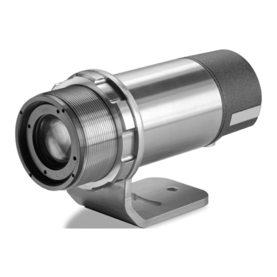
Product Description 2 Product Description The Marathon MM is a multi-purpose, high performance single color infrared pyrometer with an extensive feature set, rugged industrial housing and a high level of functionality. The sensor is available in different spectral responses to accommodate the wide range of industrial applications requiring non- contact temperature measurement. -
Page 14: Technical Data
Technical Data 3 Technical Data 3.1 Measurement Specifications Temperature Range -40 to 800°C (-40 to 1472°F) 300 to 900°C (572 to 1652°F) 250 to 1650°C (482 to 3002°F) 450 to 2250°C (842 to 4082°F) 250 to 1100°C (482 to 2012°F) 100 to 600°C (212 to 1112°F) 300 to 1100°C (572 to 2012°F) 450 to 2250°C (842 to 4082°F) - Page 15 Technical Data System Accuracy ± 1% of reading or ± 1°C for T > 0°C (32°F) meas (whichever is greater) ± 1% of reading for T > 350°C (662°F) meas ± 2°C or ± 2% for T < 350°C (662°F) meas (whichever is greater) G5L, G5H, G7...
-
Page 16: Optical Specifications
Technical Data 3.2 Optical Specifications In all cases, make sure the target completely fills the measurement spot, see section 6.1.1 Distance to Object, page 26. The actual spot size for any distance, when the unit is at focus distance, can be calculated by using the following formula. -
Page 17: Fixed Focus
Technical Data 3.2.2 Fixed Focus Optical Resolution D:S LT, MT, G5, 3M 70:1 100:1 Available Optics LT, MT, G5, 3M, G7 SF1, SF2, SF3 LT, 3M The focus distance is measured from the front end of the sensor. For units with Air/Water Cooled Housing you have to subtract 34.5 mm (1.358 in) from the focus distance. - Page 18 Technical Data SF … Standard Focus, CF … Close Focus * specified D:S ratio at focus point only Table 1: Optical Diagrams for D:S = 70:1 Marathon MM Rev. D7 Jul 2017...
- Page 19 Technical Data SF … Standard Focus, CF … Close Focus * D:S = 100:1 at focus point Table 3: Optical Diagrams for D:S = 100:1 Marathon MM Rev. D7 Jul 2017...
- Page 20 Technical Data SF … Standard Focus, CF … Close Focus * D:S = 160:1 at focus point Table 2: Optical Diagrams for D:S = 160:1 Marathon MM Rev. D7 Jul 2017...
- Page 21 Technical Data SF … Standard Focus, CF … Close Focus * D:S = 300:1 at focus point Table 3: Optical Diagrams for D:S = 300:1 Marathon MM Rev. D7 Jul 2017...
-
Page 22: Electrical Specifications
Technical Data 3.3 Electrical Specifications Power Supply 24 VDC ± 20%, min. 500 mA Outputs Analog 0 - 20 mA, 4 - 20 mA (active) 14 bit resolution max. current loop impedance: 500 Ω RS485 Interface networkable to 32 sensors Baud rate: 300, 1200, 2400, 9600, 19200, 38400 (default), 57600, 115200 (max. -
Page 23: Dimensions
Technical Data 3.5 Dimensions Figure 2: Dimensions of Sensor For the dimensional drawing of the Fixed Mounting Bracket, see section 9.2 Fixed Mounting Bracket, page 57. 3.6 Scope of Delivery The scope of delivery includes the following: • Sensor with through-the-lens sighting •... -
Page 24: Basics
Basics 4 Basics 4.1 Measurement of Infrared Temperature Everything emits an amount of infrared radiation according to its surface temperature. The intensity of the infrared radiation changes according to the temperature of the object. Depending on the material and surface properties, the emitted radiation lies in a wavelength spectrum of approximately 1 to 20 µm. -
Page 25: Environment
Environment 5 Environment Sensor location depends on the application. Before deciding on a location, you need to be aware of the ambient temperature of the location, the atmospheric quality of the location, and the possible electromagnetic interference in that location, according to the sections described above. If you plan to use air purging, you need to have an air connection available. -
Page 26: Installation
Installation 6 Installation 6.1 Mechanical Installation After all preparations are complete, you can install the sensor. How and where you anchor the sensor depends on the type of surface and the type of bracket you are using. You can mount the sensor through a hole, on a bracket of your own design, or on the available bracket accessory. -
Page 27: Viewing Angles
Installation 6.1.3 Viewing Angles The sensor head can be placed at any angle from the target up to 30°. Best 90° to target Acceptable Angles Good 30° to 90° to target 0° to 30° to target Figure 4: Acceptable Sensor Viewing Angles Marathon MM Rev. -
Page 28: Electrical Installation
Installation 6.2 Electrical Installation The 12-wire connecting cable is used to wire all inputs and outputs of the sensor. The cable comes in two different temperature versions. For more information, see section see section 9.9 Terminal Box, page 62 and section 9.11 High Temp Cable, page 64. - Page 29 Installation Figure 6: DIN Connector Pin Layout (pin side) Cable Color Description black RxA* white RxB* gray TxB** purple TxA** white/drain Shield yellow Trigger / External Input orange Relay COM blue Relay NO/NC green + mA out brown - mA out (analog ground) black Digital ground +24 VDC...
-
Page 30: Computer Interfacing
Installation 6.3 Computer Interfacing The distance between the sensor and a computer can be up to 1200 m (4000 ft.) via RS485 interface. This allows ample distance from the harsh environment where the sensing system is mounted to a control room or pulpit where the computer is located. - Page 31 Installation Converter Sensor Figure 8: Wiring the Sensor’s RS485 Interface with USB/RS485 Converter in 4-Wire Mode (factory default) Converter Sensor Figure 9: Wiring the Sensor’s RS485 Interface with USB/RS485 Converter in 2-Wire Mode Marathon MM Rev. D7 Jul 2017...
-
Page 32: Multiple Sensors In A Network
Installation 6.4 Multiple Sensors in a Network 6.4.1 Wiring For an installation of two or more sensors in a network, each sensor cable is wired to its own terminal block. The RS485 terminals on each terminal block are wired in parallel. The following figures illustrate the wiring of sensors in a 4-wire and 2-wire multidrop installation. -
Page 33: Addressing
Installation 6.4.2 Addressing The addressing of a sensor can be done by means of the Control Panel on the back of the sensor or the DataTemp Multidrop Software (Menu <Sensor Setup>) that came with your sensor. An alternative would be to use the specific interface commands of the sensor in conjunction with a standard terminal program (e.g. -
Page 34: Operation
Operation 7 Operation Once you have the sensor positioned and connected properly, the system is ready for continuous operation. The operation of the sensor can be done by means of the built-in control panel in the sensor’s housing or by means of the software that came with your sensor. 7.1 Control Panel The sensor is equipped with a control panel in the sensor’s housing, which has setting/controlling buttons and an LCD display. - Page 35 Operation Enter <Object Temp.> ◄ ► <Ambient Temp.> ◄ ► ▲ <Emissivity> 0.100 to 1.150 ▼ ◄ ► ▲ <Transmission> 0.100 to 1.000 ▼ ◄ ► ▲ <Focus> 0.2/0.3 - 2.2 ▼ ◄ ► ▲ <Laser> / On/Off/TRG ▼ <Video>...
- Page 36 Operation Object Temp.: The display shows the current temperature of the measured object. Ambient Temp.: The display shows the current internal temperature of the sensor. Emissivity: Changes the emissivity value. The emissivity is a calculated ratio of infrared energy emitted by an object to the energy emitted by a blackbody at the same temperature (a perfect radiator has an emissivity of 1.00).
-
Page 37: Signal Processing
Operation Control Panel: The control panel can be locked to avoid accidentally change of sensor operating parameters. Once locked the control panel must be unlocked by using the control panel as follows: Control Panel is locked. Press the <> button to enter Control Panel menu. Press the following buttons consecutively: <▲>... -
Page 38: Peak Hold
Operation 7.3.2 Peak Hold With Peak Hold, the respective last peak value is held until the next reset will occur. There are the following possibilities for a reset. 7.3.2.1 Reset Reset by Time: The peak will be held for a certain hold time. Once the hold time is exceeded the output signal, tracks and output the actual object temperature and the algorithm will start over again. -
Page 39: Signal Slope
Operation Reset by burst string (Burst Peak Hold): In burst mode, the peak will be held until a new burst string is being sent via the digital interface, so the effective peak hold time is defined as the time difference between two sent burst strings. In the poll mode, there is a dedicated peak hold time set to <BS>... -
Page 40: Advanced Peak Hold
Operation output temperature object temperature Temp Time Figure 19: Signal Slope defined by Decay Signal slope defined by an average time. The average time is the amount of time the output signal needs to reach 90% magnitude compared to a perpendicular drop. This parameter is set by means of the programming command <AA>. -
Page 41: Valley Hold
Operation output temperature Temp object temperature hysteresis Time Figure 21: Advanced Peak Hold For the advanced peak hold function, there are the same settings for reset and signal slope available like for the peak hold function, see sections 7.3.2.1 Reset, page 38 and 7.3.2.2 Signal Slope, page 39. -
Page 42: Inputs And Outputs
Operation 7.4 Inputs and Outputs 7.4.1 Milliamp Output The milliamp output is an analog output you can connect directly to a recording device (e.g., chart recorder), PLC, or controller. The mA output can be forced to a specific value through the DataTemp Multidrop software or a programming command according to section 10.9.1 Current Output, page 75. -
Page 43: Deadband
Operation High Threshold Deadband Low Threshold Deadband Object Temperature Relay Output Time Figure 23: Relay Output Example 7.4.2.2 Deadband Deadband is a zone of flexibility around the threshold. The alarm does not go abnormal until the temperature exceeds the threshold value by the number of set deadband degrees. Thereafter, it does not go normal until the temperature is below the threshold by the number of set deadband degrees. -
Page 44: External Input
Operation 7.4.3 External Input The external input can be used to provide the following functions: digital input for triggering digital input for On/Off switching of the laser analog input for compensating the ambient background temperature analog input for setting the emissivity Only one input function can be active at a given time. -
Page 45: Ambient Background Temperature Compensation
Operation 7.4.3.2 Ambient Background Temperature Compensation The sensor is capable of improving the accuracy of target temperature measurements by taking into account the ambient or background temperature. This feature is useful when the target emissivity is below 1.0 and the background temperature is not significantly lower than the target temperature. For instance, the higher temperature of a furnace wall could lead to too-high temperatures being measured especially for lower emissivity targets. - Page 46 Operation All ambient background temperature compensation functions are enabled through the DataTemp Multidrop software, see the software help for set up instructions, or refer to the required command protocol in section 10.8.6 Ambient Background Temperature Compensation, page 74. Sensor 2 targeted to ambient 0 –...
-
Page 47: Emissivity Setting
Operation 7.4.3.3 Emissivity Setting The external input (trigger input) can be configured to accept an analog voltage signal (0 to 5 VDC) to provide real time emissivity setting. This function is enabled through the DataTemp Multidrop Software, see the software help for set up instructions, or refer to the required command protocol in section 10.8.5 Emissivity Setting, page 74. -
Page 48: Factory Defaults
Operation 7.5 Factory Defaults The following table provides the values in case of a factory default. The factory default can only be initiated by using the DataTemp Multidrop Software. The Multidrop address and the baud rate will not change from the last value when factory default is done. Parameter Factory defaults Display mode... -
Page 49: Options
Options 8 Options Options are items that are factory installed and must be specified at time of order. The following are available: • Laser Sighting (…L) or Video Sighting (…V) • Air/Water Cooled Housing including air purge • Manufacturer's Calibration Certificate based on certified probes traced on national standards, e.g. DAkkS (XXXMMCERT) •... -
Page 50: Video Sighting
Options 8.2 Video Sighting The Marathon MM unit has optional video sighting. Video sighting is intended as a convenient way to verify correct sighting of the Marathon MM unit. Video sighting also allows for either video or frame capture of the process, enhancing process documentation. Video Specifications: Pixels: 510 x 492... - Page 51 Options Digital Video In order to utilize the frame capture functionality of the MultiDrop Software, the analog video signal must be converted into a digital signal imported via a USB port to the MultiDrop Software. The USB port on the PC must fulfill at least the USB 2.0 specification! An analog to digital video converter must be purchased locally.
- Page 52 Options Figure 32: Setting the <Auto Save> function Marathon MM Rev. D7 Jul 2017...
-
Page 53: Air/Water Cooled Housing
Options 8.3 Air/Water Cooled Housing The Air/Water Cooled Housing allows the sensor to be used in ambient temperatures up to 120°C (250°F) with air cooling, and 175°C (350°F) with water cooling. The cooling media should be connected using 1/8” NPT stainless steel fittings requiring 6 mm (0.24 in) inner diameter and 8 mm (0.31 in) outer diameter for the tube. -
Page 54: Avoidance Of Condensation
Options 8.3.1 Avoidance of Condensation If environmental conditions makes water cooling necessary, it is strictly recommended to check whether condensation will be a real problem or not. Water cooling also causes a cooling of the air in the inner part of the sensor, thereby decreasing the capability of the air to hold water. The relative humidity increases and can reach 100% very quickly. -
Page 55: Accessories
Accessories 9 Accessories 9.1 Overview Accessories include items that may be ordered at any time and added on-site. Fixed Mounting Bracket (XXXMMACFB) Adjustable Mounting Bracket (XXXMMACAB) Air Purge Collar (XXXMMACAP...) Sight Tube (XXXTST…) Pipe Thread Adapter (XXXMMACPA) ... - Page 56 Accessories Pipe Adapter Adjustable Pipe Adapter XXXMMACPA XXXTXXAPA Pipe Adapter XXXMMACPA Fixed Mounting Bracket XXXMMACFB Sensor Sight Tube XXXTST… Adjustable Mounting Bracket Right Angle Mirror XXXMMACAB XXXMMACRA... Air Purge Collar XXXMMACAP... ThermoJacket RAYTXXTJ4 Mounting Nut XXXMMACMN Protection Window XXXMMACTW… Figure 34: Accessories Marathon MM Rev.
-
Page 57: Fixed Mounting Bracket
Accessories 9.2 Fixed Mounting Bracket Figure 3: Fixed Mounting Bracket in Stainless Steel (XXXMMACFB) 9.3 Adjustable Mounting Bracket Figure 35: Adjustable Mounting Bracket in Stainless Steel (XXXMMACAB) Marathon MM Rev. D7 Jul 2017... -
Page 58: Air Purge Collar
Accessories 9.4 Air Purge Collar The Air Purge Collar accessory is used to keep dust, moisture, airborne particles, and vapors away from the optical head’s lens. It can be installed before or after the bracket. It must be screwed in fully. Air flows into the 1/8”... -
Page 59: Pipe Thread Adapter
Accessories 9.6 Pipe Thread Adapter The pipe thread adapter must be used to connect the sight tube with the sensor housing. It is made from stainless steel. Sensor Figure 38: Pipe Adapter (XXXMMACPA) Figure 39: Sensor with Sight Tube (XXXTST…) Pipe Adapter (XXXMMACPA), and Fixed Mounting Bracket (XXXMMACFB) Marathon MM Rev. -
Page 60: Right Angle Mirror
Accessories 9.7 Right Angle Mirror The Right Angle Mirror is used to turn the field of view by 90° against the sensor axis. It is recommended when space limitations or excessive radiation do not allow to directly align the sensor to the target. In dusty or contaminated environments, the air purging should be used to keep the mirror surface clean. -
Page 61: Industrial Power Supply
Accessories 9.8 Industrial Power Supply The DIN-rail mount industrial power supply delivers isolated dc power and provides short circuit and overload protection. To prevent electrical shocks, the power supply must be used in protected environments (cabinets)! Technical data: Protection class prepared for class II equipment Environmental protection IP20... -
Page 62: Terminal Box
Accessories 9.9 Terminal Box The terminal box is designed to provide IP66 (NEMA-4) protection to the terminal block, see section Electrical Installation, page 28, and a power supply for the sensor. The box should be surface mounted using the flanges and holes provided. It should be mounted in such a manner to allow the free flow of air around the unit. -
Page 63: Low Temp Cable
Accessories 9.10 Low Temp Cable The 12-wire low temp cable (XXX2CLTCB…) is used for wiring the sensor with the 24 VDC power supply, all outputs, and the RS485 interface. The cable is PUR (Polyurethane) coated and withstands ambient temperatures form -40 to 105°C (-40°F to 221°F). PUR coated cables are flexible and have good to excellent resistance to against oil, bases, and acids. -
Page 64: High Temp Cable
Accessories 9.11 High Temp Cable The 12-wire cable (XXX2CCB…) is used for wiring the sensor with the 24 VDC power supply, all outputs, and the RS485 interface. The cable is Teflon coated and withstands ambient temperatures form -80 to 200°C (-112°F to 392°F). Teflon coated temperature cables have good to excellent resistance to oxidation, heat, weather, sun, ozone, flame, water, acid, alkalis, and alcohol, but poor resistance to gasoline, kerosene, and degreaser solvents. -
Page 65: Protective Window
Accessories 9.12 Protective Window Protective windows can be used to protect the sensor’s optics against dust and other contamination. The following table provides an overview of the available protective windows recommended for the spectral models. All protective windows have a transmission below 100%. To avoid erroneous readings, ensure that the transmission for the appropriate protective window must be set in the sensor, see section 7.2 Operation... -
Page 66: Thermojacket
Accessories 9.13 ThermoJacket The ThermoJacket gives you the ability to use the sensor in ambient temperatures up to 315°C (600°F). The ThermoJacket’s rugged cast aluminum housing completely encloses the sensor and provides water and/or air cooling and air purging in one unit. The sensor can be installed or removed from the ThermoJacket housing in its mounted position. -
Page 67: Programming Guide
Programming Guide 10 Programming Guide This section explains the sensor’s communication protocol. A protocol is the set of commands that define all possible communications with the sensor. The commands are described along with their associated ASCII command characters and related message format information. Use them when writing custom programs for your applications or when communicating with your sensor with a terminal program. -
Page 68: Sensor Response
Programming Guide 10.3.3 Sensor response !E0.975<CR><LF> “!” is the parameter for “answer” “E” is the parameter “0.975” is the value for the parameter <CR> <LF> (0Dh 0Ah) is closing the answer For processing the received commands, the device needs up to 500 ms in the normal case. For certain commands, this time can be even longer, see <Time out>... -
Page 69: Checksum
Programming Guide gives the burst string parameters while in poll mode, e.g. “UTIE” gives the burst string content while in poll mode, e.g. “UC T0150.3 I0027.1 E0.950” Return from burst mode to poll mode 4-Wire Communication: send “V=P” 2-Wire Communication: send “V=P”. -
Page 70: Burst Mode
Programming Guide ASCII Binary 0010 0001 0100 0101 0011 0000 0010 1110 0011 0101 <space> 0010 0000 0100 0011 0101 0011 0111 1111 calculated checksum via XOR operation Algorithm for a character wise executed XOR operation given in exemplary Basic programming code: Bcc = 0 For I = 1 To Len(String) Bcc = Bcc Xor Asc(Mid$(String, I, 1)) -
Page 71: Minimum Baud Rate
Programming Guide characters in the burst string. Using this mode automatically sets the burst string to contain only the values for the “T”, “I” and “XT” parameters. However, the “T”, “I” and “XT” characters are removed from the burst string.. , Issuing the command $=$ sets the unit into the fastest burst and changes the format of the burst string from <T0150.3 I0027.1 XT00>... -
Page 72: Sensor Setup
Programming Guide 10.8 Sensor Setup 10.8.1 General Settings sets the physical unit for the temperature value (C or F or K). In case of a changed physical unit all temperature related parameters (e.g., thresholds) are converted automatically. E=0.950 sets the emissivity according to the setting of “ES” command A=250 sets the ambient background temperature compensation according to the setting of “AC”... - Page 73 Programming Guide FF = 1 FF = 1 ST = 20000 ST = 2000 FF = 2 FF = 2 ST = 20000 ST = 2000 Figure 49: Typical step responses at the output depending on the setting of FF and ST (example for LT sensor) Marathon MM Rev.
-
Page 74: Temperature Range
Programming Guide 10.8.4 Temperature Range The device has a standard range in which it is calibrated. This range may be extended by the internal reserve. RT=S switches to the standard temperature range RT=E switches to the extended temperature range All parameters of the technical specification (e.g. accuracy) are valid only inside the standard temperature range –... -
Page 75: Sensor Control
Programming Guide Advanced Peak Hold with decay timer or threshold 000.1-299.9 000.0 Temp. range 0001-3000 Valley Hold timer 000.0 000.1-299.9 000.0 000.0 Valley Hold trigger 000.0 300.0** 000.0 000.0 Valley Hold with decay timer 000.0 000.1-299.9 000.0 0001-3000 Advanced Valley Hold trigger or threshold 000.0 300.0** Temp. -
Page 76: External Input
Programming Guide alarm output triggered by target temperature and internal sensor temperature, N.C. normally closed alarm output triggered by internal sensor temperature, N.O. normally open alarm output triggered by internal sensor temperature, N.C. normally closed alarm output triggered by target temperature, N.O. normally open alarm output triggered by target temperature, N.C. -
Page 77: Rs485 Communication
Programming Guide 10.10 RS485 Communication The serial RS485 communication can be either in 2-wire or 4-wire mode. HM=2 sets the sensor into 2-wire communication mode. HM=4 sets the sensor into 4-wire communication mode For setting the baud rate, one of the following two commands must be selected. D=576 sets the baud rate to 57600, baud rate must be given with 3 numbers (003, 012, 024, 096, 192, 384, 576, 115). -
Page 78: Command List
Programming Guide 10.12 Command List P ... Poll, B ... Burst, S ... Set, N ... Notification (1) n = number, X = uppercase letter Description Char Format N legal values factory default Char Poll parameter ?X/?XX Set parameter X/XX=... - Page 79 Programming Guide Description Char Format N legal values factory default Char Error code nnnn hex value of ErrCode: BIT0 Object temp. over range BIT1 Object temp. under range BIT2 Internal temp. over range BIT3 Internal temp. under range BIT4 ADC initialisation error BIT5 EEPROM error user space BIT6 EEPROM error calibration...
- Page 80 Programming Guide Description Char Format N legal values factory default Char Sample time For LT, G5, MT, 3M it can be 20000 () set to the following times (in µs): 2000, 10000, 16666, 20000 or 33333 Target temperature nnnn.n ...
-
Page 81: Maintenance
Maintenance 11 Maintenance Our sales representatives and customer service are always at your disposal for questions regarding application assistance, calibration, repair, and solutions to specific problems. Please contact your local sales representative if you need assistance. In many cases, problems can be solved over the telephone. If you need to return equipment for servicing, calibration, or repair, please contact our Service Department before shipping. -
Page 82: Fail-Safe Operation
Maintenance 11.2 Fail-Safe Operation The Fail-Safe system is designed to alert the operator and provide a safe output in case of any system failure. Basically, it is designed to shutdown the process in the event of a set-up error, system error, or a failure in the sensor electronics. -
Page 83: Cleaning The Lens
Maintenance 11.3 Cleaning the Lens Keep the lens clean at all times. Care should be taken when cleaning the lens. To clean the window, do the following: Lightly blow off loose particles with “canned” air (used for cleaning computer equipment) or a small squeeze bellows (used for cleaning camera lenses). -
Page 84: Appendix
Appendix 12 Appendix 12.1 Determination of Emissivity Emissivity is a measure of an object’s ability to absorb and emit infrared energy. It can have a value between 0 and 1.0. For example a mirror has an emissivity of 0.1, while the so-called “Blackbody“ reaches an emissivity value of 1.0. - Page 85 Appendix ETALS Emissivity Material 1 µm 1.6 µm 2.3 µm 3.9 µm 5 µm 7.9 µm 8 – 14 µm Aluminum Unoxidized 0.1-0.2 0.02-0.2 0.02-0.2 0.02-0.2 0.02-0.2 0.03-0.15 0.02-0.1 Oxidized 0.2-0.4 0.2-0.4 0.2-0.4 0.20-0.55 0.2-0.4 Alloy A3003, Oxidized Roughened 0.2-0.8 0.2-0.6 0.2-0.6 0.1-0.4...
- Page 86 Appendix ETALS Emissivity Material 1 µm 1.6 µm 2.3 µm 3.9 µm 5 µm 7.9 µm 8 – 14 µm Monel (Ni-Cu) 0.2-0.6 0.2-0.6 0.1-0.5 0.1-0.5 0.10-0.25 0.1-0.14 Oxidized 0.60-0.85 0.7-0.9 Nickel Oxidized 0.8-0.9 0.4-0.7 0.4-0.7 0.3-0.6 0.3-0.6 0.80-0.95 0.2-0.5 Electrolytic 0.2-0.4 0.1-0.3...
- Page 87 Appendix ETALS Emissivity Material 1 µm 1.6 µm 2.3 µm 5 µm 7.9 µm 8 – 14 µm Asbestos 0.95 Asphalt 0.95 0.95-1.00 0.95 Basalt Carbon Unoxidized 0.8-0.95 0,8-0,9 0.8-0.9 0.8-0.9 Graphite 0.8-0.9 0.8-0.9 0.7-0.9 0.45-0.70 0.7-0.8 Carborundum 0.95 Ceramic 0.8-0.95 0.8-0.95 0.95...
-
Page 88: Notices
Notices 13 Notices Marathon MM Rev. D7 Jul 2017...
Need help?
Do you have a question about the MARATHON MM SERIES and is the answer not in the manual?
Questions and answers