
Related Manuals for Kontron 786LCD/mITX LV


Summary of Contents for Kontron 786LCD/mITX LV
-
Page 1: User Manual
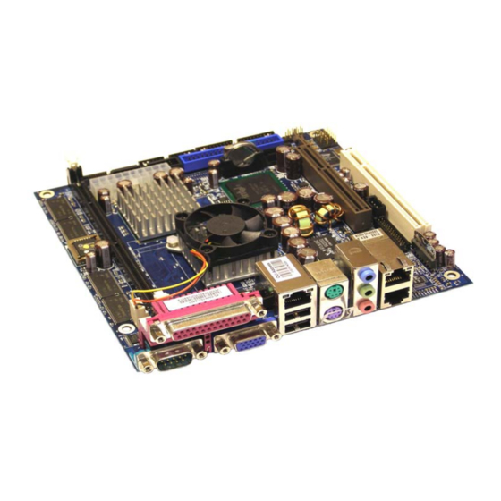
786LCD/mITX Family KTD-00629-K Public User Manual Date: 2009-10-13 Page 1 of 77 User Manual 786LCD/mITX family 786LCD/mITX LV (733/133MHz) 786LCD/mITX ULV (400/100MHz) -
Page 2: Document Revision History
Brand and product names are trademarks or registered trademarks of their respective owners. Disclaimer: KONTRON Technology A/S reserves the right to make changes, without notice, to any product, including circuits and/or software described or contained in this manual in order to improve design and/or performance. -
Page 3: Life Support Policy
KONTRON Technology Technical Support and Services If you have questions about installing or using your KONTRON Technology Product, check this User’s Manual first – you will find answers to most questions here. To obtain support, please contact your local Distributor or Field Application Engineer (FAE). -
Page 4: Table Of Contents
Power consumption.........................14 System overview ..........................15 786LCD Clock Distribution......................16 CONNECTOR DEFINITIONS........................17 Connector layout..........................18 4.1.1 786LCD/mITX LV Plus........................18 4.1.2 786LCD/mITX ULV Standard .....................19 Power Connector (ATXPWR) ......................20 Keyboard and PS/2 mouse connectors ..................21 4.3.1 Stacked MINI-DIN keyboard and mouse Connector (MSE & KBD) ...........21 4.3.2... - Page 5 786LCD/mITX Family KTD-00629-K Public User Manual Date: 2009-10-13 Page 5 of 77 4.10.1 Ethernet connector 1 (ETHER1)....................36 4.10.2 Ethernet connector 2/3 (ETHER2/3)...................37 4.11 USB Connector (USB)........................38 4.11.1 USB Connector 0/3 (USB0/3).....................38 4.11.2 USB Connector 2/5 (USB25)......................38 4.12 Audio Connector ..........................39 4.12.1 Audio Line-in, Line-out and Microphone..................39 4.12.2...
- Page 6 786LCD/mITX Family KTD-00629-K Public User Manual Date: 2009-10-13 Page 6 of 77 8.3.11 Advanced settings – USB Mass Storage Device Configuration..........63 8.3.12 Advanced settings – ACPI Settings....................64 8.3.13 Advanced settings – General ACPI Configuration ..............65 8.3.14 Advanced settings – Advanced ACPI Configuration ..............65 PCIPnP Menu............................66 Boot Menu............................67 8.5.1...
-
Page 7: Introduction
7 of 77 1. Introduction This manual describes the 786LCD/mITX board made by KONTRON Technology A/S. The boards will also be denoted 786LCD family if no differentiation is required. All boards are to be used with the Intel® Celeron® LV and ULV Processors. -
Page 8: Installation Procedure
2. Installation procedure 2.1 Installing the board To get the board running, follow these steps. In some cases the board shipped from KONTRON Technology has SDRAM mounted. In this case Step 2 can be skipped. 1. Turn off the power supply. -
Page 9: Requirement According To En60950
786LCD/mITX Family KTD-00629-K Public User Manual Date: 2009-10-13 Page 9 of 77 2.2 Requirement according to EN60950 Users of 786LCD boards should take care when designing chassis interface connectors in order to fulfill the EN60950 standard: When an interface/connector has a VCC (or other power) pin, which is directly connected to a power plane like the VCC plane: To protect the external power lines of peripheral devices the customer has to take care about: •... -
Page 10: System Specification
786LCD/mITX Family KTD-00629-K Public User Manual Date: 2009-10-13 Page 10 of 77 3. System specification 3.1 Component main data The table below summarises the features of the 786LCD/mITX embedded motherboard. 786LCD/mITX: mini ITX (170.18millimeters by 170.18millimeters) Form factor • Support for Intel Celeron LV and Celeron ULV Processors in mPGA478 socket Processor with 400MHz system bus. - Page 11 1x 10/100Mbits/s LAN subsystem using the Realtek RTL8100C LAN controllers depending on board configuration. PXE and RPL netboot supported. Wake On LAN (WOL) supported. • Kontron Technology / AMI BIOS (core version) BIOS • Support for Advanced Configuration and Power Interface (ACPI 1.0, 2.0), Plug...
- Page 12 786LCD/mITX Family KTD-00629-K Public User Manual Date: 2009-10-13 Page 12 of 77 Environmental Operating: Conditions 0°C – 60°C operating temperature (forced cooling). It is the customer’s responsibility to provide sufficient airflow around each of the components to keep them within allowed temperature range.
-
Page 13: Configuration Overview
Public User Manual Date: 2009-10-13 Page 13 of 77 3.2 Configuration overview Feature 810045-4500, 786LCD/mITX LV Plus 810046-4500, 786LCD/mITX ULV Standard Intel Celeron LV 733MHz Intel Celeron ULV 400 MHz 256MB SDRAM, PC133 Onboard Memory Yes (Max. 1280x1024) Yes (Max. 1024x768) -
Page 14: System Memory Support
ECC not supported The onboard memory is: • 0 MB (786LCD/mITX ULV Standard) • 256 MB/ PC133 (786LCD/mITX LV Plus) The socket memory can be: • 168-pin PC100/PC133 SDRAM DIMMs from 32 MB to 256 MB • Single - or double sided DIMMs with gold-plated contacts. -
Page 15: System Overview
786LCD/mITX Family KTD-00629-K Public User Manual Date: 2009-10-13 Page 15 of 77 3.5 System overview The block diagram below shows the architecture and main components of the 786LCD boards. The two key ® ® components on the board are the Intel 815E and Intel ICH4 Embedded Chipsets. -
Page 16: 786Lcd Clock Distribution
786LCD/mITX Family KTD-00629-K Public User Manual Date: 2009-10-13 Page 16 of 77 3.6 786LCD Clock Distribution... -
Page 17: Connector Definitions
786LCD/mITX Family KTD-00629-K Public User Manual Date: 2009-10-13 Page 17 of 77 4. Connector Definitions The following sections provide pin definitions and detailed description of all on-board connectors. The connector definitions follow the following notation: Column Description name Shows the pin-numbers in the connector. The graphical layout of the connector definition tables is made similar to the physical connectors. -
Page 18: Connector Layout
786LCD/mITX Family KTD-00629-K Public User Manual Date: 2009-10-13 Page 18 of 77 4.1 Connector layout 4.1.1 786LCD/mITX LV Plus Clr-CMOS CF (backside of 786LCD/mITX) SATA1 FRONTPNL USB25 IDE_S2 SATA0 FEATURE LVDS IDE_P IEEE1394x2 ATXPWR CDROM SDRAM KBDMSE COM3 SYSTEM COM4... -
Page 19: 786Lcd/Mitx Ulv Standard
786LCD/mITX Family KTD-00629-K Public User Manual Date: 2009-10-13 Page 19 of 77 4.1.2 786LCD/mITX ULV Standard Clr-CMOS CF (backside of 786LCD/mITX) FRONTPNL USB25 LVDS IDE_S2 FEATURE IDE_P ATXPWR CDROM SDRAM KBDMSE COM3 SYSTEM COM4 COM2 AUDIO LPC IFC LINE-IN CPU FAN ETHER1 LINE-OUT USB3... -
Page 20: Power Connector (Atxpwr)
786LCD/mITX Family KTD-00629-K Public User Manual Date: 2009-10-13 Page 20 of 77 4.2 Power Connector (ATXPWR) The 786LCD/mITX is designed to be supplied from a standard ATX power supply. Power Connector 786LCD/mITX Pull Pull Note Ioh/Iol Type Signal Signal Type Ioh/Iol Note +12V... -
Page 21: Keyboard And Ps/2 Mouse Connectors
786LCD/mITX Family KTD-00629-K Public User Manual Date: 2009-10-13 Page 21 of 77 4.3 Keyboard and PS/2 mouse connectors Attachment of a keyboard or PS/2 mouse adapter can be done through the stacked PS/2 mouse and keyboard connector (MSE & KBD). Both interfaces utilize open-drain signaling with on-board pull-up. -
Page 22: Display Connectors
786LCD/mITX Family KTD-00629-K Public User Manual Date: 2009-10-13 Page 22 of 77 4.4 Display Connectors The 786LCD board family provides onboard two basic types of interfaces to a display: Analog CRT interface and a digital interface available as either LVDS dual channel interface or DVI (analogue/ digital) depending on the board configuration. -
Page 23: Lvds Flat Panel Connector (Lvds)
786LCD/mITX Family KTD-00629-K Public User Manual Date: 2009-10-13 Page 23 of 77 4.4.2 LVDS Flat Panel Connector (LVDS) Note Type Signal Signal Type Note +12V +12V +12V +12V +12V LCDVCC LCDVCC 4K7Ω, 3.3V DDC CLK DDC DATA 4K7Ω, 3.3V 4.7V level BKLTCTL VDD ENABLE 3.3V level... -
Page 24: Dvi Interface Connector (Dvi Ifc)
786LCD/mITX Family KTD-00629-K Public User Manual Date: 2009-10-13 Page 24 of 77 4.4.3 DVI Interface Connector (DVI IFC) DVI functionality is not supported on actual 786LCD/mITX versions therefore the DVI IFC connector is not mounted. Note Type Signal Signal Type Note LCDCK LCDDA... -
Page 25: Agp Connector - Tbd
786LCD/mITX Family KTD-00629-K Public User Manual Date: 2009-10-13 Page 25 of 77 4.4.4 AGP connector - TBD Note Type Signal Signal Type Note OVRCNT +12V TYPEDET RSVD USB+ USB- INTB INTA AGPCLK RST- GREQ GGNT +3.3V +3.3V RSVD PIPE RSVD SBA(0) SBA(1) +3.3V... - Page 26 786LCD/mITX Family KTD-00629-K Public User Manual Date: 2009-10-13 Page 26 of 77 Signal Description – AGP Connector: Signal Description Address PIPE# Pipeline. During PIPE# Operation. This signal is asserted by the AGP master to indicate a full-width address is to be enqueued on by the target using the AD bus.
- Page 27 786LCD/mITX Family KTD-00629-K Public User Manual Date: 2009-10-13 Page 27 of 77 During FRAME# Operation: G_FRAME# is an output when the GMCH acts as an initiator on the AGP Interface. G_FRAME# is asserted by the GMCH to indicate the beginning and duration of an access.
- Page 28 786LCD/mITX Family KTD-00629-K Public User Manual Date: 2009-10-13 Page 28 of 77 CBE#[3:0] Command/Byte Enable. During FRAME# Operation: During the address phase of a transaction, the G_CBE[3:0]# signals define the bus command. During the data phase, the G_CBE[3:0]# signals are used as byte enables.
-
Page 29: Parallel Ata Harddisk Interface
786LCD/mITX Family KTD-00629-K Public User Manual Date: 2009-10-13 Page 29 of 77 4.5 Parallel ATA harddisk interface Two parallel ATA harddisk controllers are available on the board – a primary and a secondary controller. Standard 3½” harddisks or CD-ROM drives may be attached to the primary controller board by means of the 40 pin IDC connectors, IDE_P. -
Page 30: Ide Hard Disk Connector (Ide_P)
786LCD/mITX Family KTD-00629-K Public User Manual Date: 2009-10-13 Page 30 of 77 4.5.1 IDE Hard Disk Connector (IDE_P) This connector can be used for connection of two primary IDE drives. Pull Pull Note Ioh/Iol Type Signal Signal Type Ioh/Iol Note RESETA# /10K DA10... -
Page 31: Cf Connector (Cf)
786LCD/mITX Family KTD-00629-K Public User Manual Date: 2009-10-13 Page 31 of 77 4.5.3 CF Connector (CF) This connector is mounted on the backside of the 786LCD-M/mITX. If a Compact Flash Disk is used, then no IDE drive can be connected to the IDE_S2 connector. The socket support DMA/UDMA modules up to UDMA2. -
Page 32: Serial Ata Harddisk Interface
786LCD/mITX Family KTD-00629-K Public User Manual Date: 2009-10-13 Page 32 of 77 4.6 Serial ATA harddisk interface Two serial ATA harddisk controllers are available on the board – a primary controller (SATA0) and a secondary controller (SATAB). 4.6.1 SATA Hard Disk Connector (SATA0, SATA1) SATA0: Pull Signal... -
Page 33: Firewire / Ieee1394 Connector
786LCD/mITX Family KTD-00629-K Public User Manual Date: 2009-10-13 Page 33 of 77 4.7 Firewire / IEEE1394 connector The 786LCD/mITX supports two IEEE Std 1394a-2000 fully compliant cable ports at 100M bits/s, 200M bits/s, and 400M bits/s. 4.7.1 IEEE1394 Connector (IEEE1394_0 and IEEE1394_1) The pinout of the Firewire / IEEE1394 connector IEEE1394_0 and IEEE1394_1 is as follows: Pull Pull... -
Page 34: Printer Port Connector (Printer)
786LCD/mITX Family KTD-00629-K Public User Manual Date: 2009-10-13 Page 34 of 77 4.8 Printer Port Connector (PRINTER). The printer port connector is provided in a standard DB25 pinout. The signal definition in standard printer port mode is as follows: Pull Pull Note Ioh/Iol... -
Page 35: Serial Ports
786LCD/mITX Family KTD-00629-K Public User Manual Date: 2009-10-13 Page 35 of 77 4.9 Serial Ports Four RS232C serial ports are available on the 786LCD/mITX. The typical interpretation of the signals in the Serial Ports is as follows: Signal Description Transmitte Data, sends serial data to the communication link. The signal is set to a marking state on hardware reset when the transmitter is empty or when loop mode operation is initiated. -
Page 36: Ethernet Connectors
786LCD/mITX Family KTD-00629-K Public User Manual Date: 2009-10-13 Page 36 of 77 4.10 Ethernet connectors. The 786LCD/mITX boards supports 3 channels of 10/100Mb Ethernet. In order to achieve the specified performance of the Ethernet port, Category 5 twisted pair cables must be used with 10/100MB LAN networks. -
Page 37: Ethernet Connector 2/3 (Ether2/3)
786LCD/mITX Family KTD-00629-K Public User Manual Date: 2009-10-13 Page 37 of 77 4.10.2 Ethernet connector 2/3 (ETHER2/3) The two Ethernet channels in ETHER2/3 are supported by two discrete Ethernet controllers (RTL8100C) connected to the onboard PCI bus. The pinout of the RJ45’s connector are as follows: Signal Type Ioh/Iol... -
Page 38: Usb Connector (Usb)
786LCD/mITX Family KTD-00629-K Public User Manual Date: 2009-10-13 Page 38 of 77 4.11 USB Connector (USB) The ICH4 contains an Enhanced Host Controller Interface (EHCI) compliant host controller that supports USB high-speed signaling. High-speed USB 2.0 allows data transfers up to 480 Mb/s which is 40 times faster than full-speed USB. -
Page 39: Audio Connector
786LCD/mITX Family KTD-00629-K Public User Manual Date: 2009-10-13 Page 39 of 77 4.12 Audio Connector 4.12.1 Audio Line-in, Line-out and Microphone Audio Line-in, Line-out and Microphone are available in the stacked audio jack connector. Signal Type Note Line in – Left RING Line in –... -
Page 40: Audio Header (Audio Header)
786LCD/mITX Family KTD-00629-K Public User Manual Date: 2009-10-13 Page 40 of 77 4.12.3 AUDIO Header (AUDIO HEADER) Pull Ioh/ Ioh/ Pull Note Type Signal Signal Type Note LFE-OUT CEN-OUT AAGND AAGND SPKR_OUT_L SPKR_OUT_R AAGND AAGND SURR-OUT-L SURR-OUT-R 11 12 AAGND 13 14 AAGND F-FRONT-MIC1... -
Page 41: Fan Connectors , System Fan And Cpu Fan
786LCD/mITX Family KTD-00629-K Public User Manual Date: 2009-10-13 Page 41 of 77 4.13 Fan connectors , SYSTEM FAN and CPU FAN. The SYSTEM FAN can be used to power, control and monitor a fan for chassis ventilation etc. The CPU FAN is used for connection of the active cooler for the CPU. Pull Signal Type... -
Page 42: Front Panel Connector (Frontpnl)
786LCD/mITX Family KTD-00629-K Public User Manual Date: 2009-10-13 Page 42 of 77 4.16 Front Panel connector (FRONTPNL). Pull Pull Note Ioh/Iol Type Signal Signal Type Ioh/Iol Note USB14_5V USB14_5V USB1- USB4- USB1+ USB4+ 11 12 HD_LED 13 14 SUS_LED 15 16 PWRBTN_IN# RSTIN# 17 18... -
Page 43: Feature Connector (Feature)
General Purpose Inputs / Output. These Signals may be controlled or monitored through GPIO0..7 the use of the KONTRON API (Application Programming Interface) available for Win98, WinXP, WinNT, and Win2000. FAN 3 speed control OUTput (1), PWM (high impedanse) output signal to implement voltage in the range 0-4.7V in steps of 0.3V. -
Page 44: Pci Slot Connector
786LCD/mITX Family KTD-00629-K Public User Manual Date: 2009-10-13 Page 44 of 77 4.17.1 PCI Slot Connector Terminal Note Type Signal Signal Type Note -12V TRST# +12V INTA# INTB# INTC# INTD# REQ2# CLKC REQ3# +5V (I/O) GNT2# CLKD CLKA GNT3# RST# CLKB +5V (I/O) GNT0#... -
Page 45: Signal Description -Pci Slot Connector
786LCD/mITX Family KTD-00629-K Public User Manual Date: 2009-10-13 Page 45 of 77 4.17.2 Signal Description –PCI Slot Connector SYSTEM PINS Clock provides timing for all transactions on PCI and is an input to every PCI device. All other PCI signals, except RST#, INTA#, INTB#, INTC#, and INTD#, are sampled on the rising edge of CLK and all other timing parameters are defined with respect to this edge. -
Page 46: 786Lcd Pci Irq & Int Routing
786LCD/mITX Family KTD-00629-K Public User Manual Date: 2009-10-13 Page 46 of 77 ARBITRATION PINS (BUS MASTERS ONLY) Request indicates to the arbiter that this agent desires use of the bus. This is a point to point signal. Every REQ# master has its own REQ# which must be tri-stated while RST# is asserted. Grant indicates to the agent that access to the bus has been granted. -
Page 47: Onboard Connectors
Molex 22-23-2061 Molex 22-01-2065 CDROM Foxconn HF1104E Molex 50-57-9404 Molex 70543-0038 SATA0 Molex 67491-0020 Molex 67489-8005 SATA1 Kontron KT 821035 (cable kit) ATXPWR FoxConn HM2510E Molex 39-01-2205 COM2 Foxconn HL20051 Molex 90635-1103 COM3 Kontron KT 821016 (cable kit) COM4 Kontron... -
Page 48: System Ressources
786LCD/mITX Family KTD-00629-K Public User Manual Date: 2009-10-13 Page 48 of 77 6. System Ressources 6.1 Memory map The table below lists the system memory map. Address range (hex) Size Description 00000000- 0007FFFF 512 Kbytes Conventional memory 00080000- 0009FBFF 127 Kbyte Extended conventional memory 0009FC00- 0009FFFF... -
Page 49: Interrupt Usage
786LCD/mITX Family KTD-00629-K Public User Manual Date: 2009-10-13 Page 49 of 77 6.3 Interrupt Usage Notes • • IRQ0 • IRQ1 • IRQ2 • • • • • 1, 2 IRQ3 • • • • • 1, 2 IRQ4 • •... -
Page 50: I/O Map
786LCD/mITX Family KTD-00629-K Public User Manual Date: 2009-10-13 Page 50 of 77 6.4 I/O Map Address (hex) Size Description 0020- 0021 Programmable interrupt controller 0040- 0043 System Timer 0060- 0060 Standard keyboard 0061- 0061 System speaker 0070- 0071 System CMOS/Real time clock 0170- 01F7 Secondary Parallel ATA IDE Channel... -
Page 51: Overview Of Bios Features
7. Overview of BIOS features This Manual section details specific BIOS features for the 786LCD/mITX boards. The 786LCD/mITX boards are based on the AMI BIOS core version 8.10 with Kontron BIOS extensions. 7.1.1 System Management BIOS (SMBIOS / DMI) SMBIOS is a Desktop Management Interface (DMI) compliant method for managing computers in a managed network. -
Page 52: Bios Configuration / Setup
786LCD/mITX Family KTD-00629-K Public User Manual Date: 2009-10-13 Page 52 of 77 8. BIOS Configuration / Setup 8.1 Introduction The BIOS Setup is used to view and configure BIOS settings for the 786LCD/mITX board. The BIOS Setup is accessed by pressing the DEL key after the Power-On Self-Test (POST) memory test begins and before the operating system boot begins. -
Page 53: Advanced Menu
786LCD/mITX Family KTD-00629-K Public User Manual Date: 2009-10-13 Page 53 of 77 8.3 Advanced Menu BIOS SETUP UTILITY Main Advanced PCIPnP Boot Security Chipset Power Exit Configure CPU. Advanced Settings Warning: Setting wrong values in below sections May cause system to malfunction. >... -
Page 54: Advanced Settings - Ide Configuration
786LCD/mITX Family KTD-00629-K Public User Manual Date: 2009-10-13 Page 54 of 77 8.3.2 Advanced settings – IDE Configuration BIOS SETUP UTILITY Advanced DISABLED: disables the IDE Configuration integrated IDE OnBoard PCI IDE Controller [Both] controller. PRIMARY: enables only > Primary IDE Master : [Not Detected] the Primary IDE >... - Page 55 786LCD/mITX Family KTD-00629-K Public User Manual Date: 2009-10-13 Page 55 of 77 BIOS SETUP UTILITY Advanced Select the type of Primary IDE Master devices connected to Device :Hard Disk the system. Vendor :ST340014A Size :40.0GB LBA Mode :Supported Block Mode :16Sectors PIO Mode S.M.A.R.T.
-
Page 56: Advanced Settings - Lan Configuration
786LCD/mITX Family KTD-00629-K Public User Manual Date: 2009-10-13 Page 56 of 77 Feature Options Description Hard Disk Write Protect Enable write protection on HDDs, only works when it is Disable Enabled accessed through the BIOS IDE Detect Time Out (Sec) Select the time out value when the BIOS is detecting ATA/ATAPI Devices ATA(PI) 80Pin Cable... -
Page 57: Advanced Settings - Sata/Raid Configuration
786LCD/mITX Family KTD-00629-K Public User Manual Date: 2009-10-13 Page 57 of 77 8.3.4 Advanced settings – SATA/RAID Configuration BIOS SETUP UTILITY Advanced Configure the Serial SATA/RAID Configuration ATA Device. SATA/RAID Configuration [Enabled] <- Select Screen Select Item change option General Help Save and Exit Exit V02.58 (C)Copyright 1985-2005, American Megatrends, Inc. -
Page 58: Advanced Settings - Superio Configuration
786LCD/mITX Family KTD-00629-K Public User Manual Date: 2009-10-13 Page 58 of 77 8.3.6 Advanced settings – SuperIO Configuration BIOS SETUP UTILITY Advanced Allows BIOS to Select Configure Win627THF Super IO Chipset Serial Port1 Base Serial Port1 Address [3F8/IRQ4] Addresses. Serial Port2 Address [2F8/IRQ3] Serial Port2 Mode [Normal]... -
Page 59: Advanced Settings - Voltage Monitor
786LCD/mITX Family KTD-00629-K Public User Manual Date: 2009-10-13 Page 59 of 77 8.3.7 Advanced settings – Voltage Monitor BIOS SETUP UTILITY Advanced Voltage Monitor Requested Core :1.150 V VcoreA :1.031 V VcoreB :1.516 V +3.3Vin :3.290 V +5Vin :5.012 V +12Vin :12.016 V <-... -
Page 60: Advanced Settings - Hardware Health Configuration
786LCD/mITX Family KTD-00629-K Public User Manual Date: 2009-10-13 Page 60 of 77 8.3.8 Advanced settings – Hardware Health Configuration BIOS SETUP UTILITY Advanced IF exceeded, throttle Hardware Health Event Monitoring event will be engaged System Temperature :47ºC/116ºF CPU Temperature :48ºC/118ºF Choose impact via THRM throttle limit [Disabled]... -
Page 61: Advanced Settings - Remote Access Configuration
786LCD/mITX Family KTD-00629-K Public User Manual Date: 2009-10-13 Page 61 of 77 8.3.9 Advanced settings – Remote Access Configuration BIOS SETUP UTILITY Advanced Select Remote Access Configure Remote Access type and parameters type. Remote Access [Enabled] Serial port number [COM1] Base Address, IRQ [3F8h, 4] Serial Port Mode... -
Page 62: Advanced Settings - Usb Configuration
786LCD/mITX Family KTD-00629-K Public User Manual Date: 2009-10-13 Page 62 of 77 8.3.10 Advanced settings – USB Configuration BIOS SETUP UTILITY Advanced Enables support for USB Configuration legacy USB. Auto Module Version – 2.23.2-9.4 option disables legacy support if no USB USB Devices Enabled : devices are connected. -
Page 63: Advanced Settings - Usb Mass Storage Device Configuration
786LCD/mITX Family KTD-00629-K Public User Manual Date: 2009-10-13 Page 63 of 77 8.3.11 Advanced settings – USB Mass Storage Device Configuration BIOS SETUP UTILITY Advanced Enables support for USB Mass Storage Device Configuration legacy USB. Auto USB Mass Storage Reset Delay [20 Sec] option disables legacy support if no USB... -
Page 64: Advanced Settings - Acpi Settings
786LCD/mITX Family KTD-00629-K Public User Manual Date: 2009-10-13 Page 64 of 77 8.3.12 Advanced settings – ACPI Settings BIOS SETUP UTILITY Advanced Enable / Disable ACPI ACPI Settings support for Operating ACPI Aware O/S [Yes] System. > General ACPI Configuration ENABLE: If OS supports >... -
Page 65: Advanced Settings - General Acpi Configuration
786LCD/mITX Family KTD-00629-K Public User Manual Date: 2009-10-13 Page 65 of 77 8.3.13 Advanced settings – General ACPI Configuration BIOS SETUP UTILITY Advanced Select the ACPI state General ACPI Configuration used for System Suspend mode [S1 & S3 (STR)] Suspend. Repost Video on S3 Resume [Yes] <-... -
Page 66: Pcipnp Menu
786LCD/mITX Family KTD-00629-K Public User Manual Date: 2009-10-13 Page 66 of 77 8.4 PCIPnP Menu BIOS SETUP UTILITY PCIPnP NO: lets the BIOS Advanced PCI/PnP Settings configure all the Warning: Setting wrong values in below sections devices in the system. May cause system to malfunction. -
Page 67: Boot Menu
786LCD/mITX Family KTD-00629-K Public User Manual Date: 2009-10-13 Page 67 of 77 8.5 Boot Menu BIOS SETUP UTILITY Main Advanced PCIPnP Boot Security Chipset Power Exit Configure Settings Boot Settings during System Boot. > Boot Settings Configuration > Boot Device Priority Auto adjust Boot Priority [Yes] <-... -
Page 68: Boot - Boot Settings Configuration
786LCD/mITX Family KTD-00629-K Public User Manual Date: 2009-10-13 Page 68 of 77 8.5.1 Boot – Boot Settings Configuration BIOS SETUP UTILITY Boot Allows BIOS to skip Boot Settings certain tests while booting. This will Quick Boot [Enabled] decrease the time Quiet Boot [Disabled] needed to boot the... -
Page 69: Boot - Boot Device Priority
786LCD/mITX Family KTD-00629-K Public User Manual Date: 2009-10-13 Page 69 of 77 8.5.2 Boot – Boot Device Priority BIOS SETUP UTILITY Boot Specifies the boot Boot Device Priority sequence from the available devices. 1st Boot Device [“device name”] 2nd Boot Device [“device name”] <- Select Screen... -
Page 70: Security Menu
786LCD/mITX Family KTD-00629-K Public User Manual Date: 2009-10-13 Page 70 of 77 8.6 Security Menu BIOS SETUP UTILITY Main Advanced PCIPnP Boot Security Chipset Power Exit Install or Change the Security Settings password. Supervisor Password :Installed User Password :Installed Change Supervisor Password Change User Password Clear User Password Boot Sector Virus Protection... -
Page 71: Chipset Menu
786LCD/mITX Family KTD-00629-K Public User Manual Date: 2009-10-13 Page 71 of 77 8.7 Chipset Menu BIOS SETUP UTILITY Main Advanced PCIPnP Boot Security Chipset Power Exit Advanced Chipset Settings Intel ICH4 SouthBridge chipset configuration options. Warning: Setting wrong values in below sections may cause system to malfunction. - Page 72 786LCD/mITX Family KTD-00629-K Public User Manual Date: 2009-10-13 Page 72 of 77 Feature Options Description ICH4 Dev31 Func1, IDE Disabled, Enabled Enable / Disable ICH4 IDE Controller function. ICH4 Dev31 Func3, Disabled, Enabled Enable / Disable ICH4 SMBUS Controller function. SMBUS ICH4 Dev31 Func5, AC’97 Disabled, Enabled...
-
Page 73: Power Menu
786LCD/mITX Family KTD-00629-K Public User Manual Date: 2009-10-13 Page 73 of 77 8.8 Power Menu BIOS SETUP UTILITY Main Advanced PCIPnP Boot Security Chipset Power Exit Enable or Disable APM. APM Configuration Power Management/APM [Enabled] Power Button Mode [On/Off] Force Throttle [Disabled] THRM throttle Ratio [50%]... -
Page 74: Exit Menu
786LCD/mITX Family KTD-00629-K Public User Manual Date: 2009-10-13 Page 74 of 77 8.9 Exit Menu BIOS SETUP UTILITY Main Advanced PCIPnP Boot Security Chipset Power Exit Exit system setup Exit Options after saving the changes. Save Changes and Exit Discard Changes and Exit F10 Key can be used Discard Changes for this operation. -
Page 75: Ami Bios Beep Codes
786LCD/mITX Family KTD-00629-K Public User Manual Date: 2009-10-13 Page 75 of 77 8.10 AMI BIOS Beep Codes Boot Block Beep Codes: Number of Description Beeps Insert diskette in floppy drive A: ‘AMIBOOT.ROM’ file not found in root directory of diskette in A: Base Memory error Flash Programming successful Floppy read error... -
Page 76: Os Setup
SATA disk(s) USB FDD Required SW: The file 786LCDmITX_Raid_Driver_Windows which can be downloaded from www.kontron-emea.com. The files shall be unzipped and the files (txt-file and doc-file are not needed) shall be copied to the Floppy Disk. The file contains: Readme.txt SiISupp.cpl... -
Page 77: Warranty
77 of 77 10. Warranty KONTRON Technology warrants its products to be free from defects in material and workmanship during the warranty period. If a product proves to be defective in material or workmanship during the warranty period, KONTRON Technology will, at its sole option, repair or replace the product with a similar product.
Need help?
Do you have a question about the 786LCD/mITX LV and is the answer not in the manual?
Questions and answers