Table of Contents
Advertisement
Quick Links
Download this manual
See also:
User Manual
Advertisement
Table of Contents

Related Manuals for Kontron KTUS15/mITX 1.6GHz Std


Summary of Contents for Kontron KTUS15/mITX 1.6GHz Std
-
Page 1: User Manual
KTUS15 Family KTD-00774-0 Public User Manual Date: 2008-12-29 Page 1 of 61 User Manual for the Motherboards: KTUS15/mITX Board Family... -
Page 2: Document Revision History
Brand and product names are trademarks or registered trademarks of their respective owners. Disclaimer: KONTRON Technology A/S reserves the right to make changes, without notice, to any product, including circuits and/or software described or contained in this manual in order to improve design and/or performance. -
Page 3: Life Support Policy
KONTRON Technology Technical Support and Services If you have questions about installing or using your KONTRON Technology Product, check this User’s Manual first – you will find answers to most questions here. To obtain support, please contact your local Distributor or Field Application Engineer (FAE). -
Page 4: Table Of Contents
KTUS15 Family KTD-00774-0 Public User Manual Date: 2008-12-29 Page 4 of 61 Table of contents: INTRODUCTION .............................6 INSTALLATION PROCEDURE ......................7 Installing the board..........................7 Requirement according to EN60950 ....................8 SYSTEM SPECIFICATION ........................9 Component main data ........................9 System overview ..........................12 KTUS15/mITX Board configurations....................13 System Memory support .........................14 3.4.1 Memory Operating Frequencies ....................14... - Page 5 KTUS15 Family KTD-00774-0 Public User Manual Date: 2008-12-29 Page 5 of 61 Serial Ports ............................34 4.9.1 Com1, 2, 3, 4 Pin Header Connector..................34 4.10 Ethernet connectors........................35 4.10.1 Ethernet connector (LAN) ......................35 4.11 USB Connector (USB)........................36 4.11.1 USB Connector 0/2 (USB0/2).....................37 4.11.2 USB Connector 4/5 (USB4/5).....................37 4.11.3...
-
Page 6: Introduction
6 of 61 1. Introduction This manual describes the KTUS15/mITX boards made by KONTRON Technology A/S. The boards will also be denoted KTUS15 family if no differentiation is required. The boards use the Dual-Core Intel® Atom™ processor together with the Intel® US15W chipset. -
Page 7: Installation Procedure
2. Installation procedure Installing the board To get the board running, follow these steps. In some cases the board shipped from KONTRON Technology has DDR2 DRAM mounted. In this case Step 2 can be skipped. 1. Turn off the power supply 2. -
Page 8: Requirement According To En60950
KTUS15 Family KTD-00774-0 Public User Manual Date: 2008-12-29 Page 8 of 61 Requirement according to EN60950 Users of KTUS15 family boards should take care when designing chassis interface connectors in order to fulfill the EN60950 standard: When an interface/connector has a VCC (or other power) pin, which is directly connected to a power plane like the VCC plane: To protect the external power lines of peripheral devices the customer has to take care about: •... -
Page 9: System Specification
KTUS15 Family KTD-00774-0 Public User Manual Date: 2008-12-29 Page 9 of 61 3. System specification Component main data The table below summarises the features of the KTUS15/mITX embedded motherboards. KTUS15/mITX: mini ITX (170.18millimeters by 170.18millimeters) Form factor Processor • Intel® Atom™ BGA processors 1.1GHz (Z510) or 1.6GHz (Z530) depending on board configuration. - Page 10 • RPL/PXE netboot supported. Wake On LAN (WOL) supported (S3 only). • BIOS Kontron Technology / AMI BIOS (core version 8.00) • Support for Advanced Configuration and Power Interface (ACPI 3.0), Plug and Play Suspend To Ram Suspend To Disk Intel Speed Step •...
- Page 11 KTUS15 Family KTD-00774-0 Public User Manual Date: 2008-12-29 Page 11 of 61 Environmental Operating: Conditions 0°C – 60°C operating temperature (forced cooling). It is the customer’s responsibility to provide sufficient airflow around each of the components to keep them within allowed temperature range.
-
Page 12: System Overview
KTUS15 Family KTD-00774-0 Public User Manual Date: 2008-12-29 Page 12 of 61 System overview The block diagram below shows the architecture and main components of the KTUS15 family boards. Components shown shaded are optional depending on variants of the board. -
Page 13: Ktus15/Mitx Board Configurations
KTUS15 Family KTD-00774-0 Public User Manual Date: 2008-12-29 Page 13 of 61 3.3 KTUS15/mITX Board configurations P/N 810290 P/N 810291 P/N 810292 P/N 810293 KTUS15/mITX KTUS15/mITX KTUS15/mITX KTUS15/mITX 1.6GHz Std 1.1GHz Basic 1.6GHz Plus 1.1GHz Std Processor Z530, 1.6GHz Z510, 1.1GHz Z530, 1.6GHz Z510, 1.1GHz FSB speed... -
Page 14: System Memory Support
KTUS15 Family KTD-00774-0 Public User Manual Date: 2008-12-29 Page 14 of 61 System Memory support The KTUS15 boards have one 200-pin DDR2 Small Outline Dual Inline Memory Module (SO-DIMM) socket. The socket can be populated with up to 2 GB (* to be confirmed) of unbuffered DDR2 SO-DIMM modules. Memory speeds up to 533MT/s (PC2-4200) are supported. -
Page 15: Ktus15 Graphics Subsystem
KTUS15 Family KTD-00774-0 Public User Manual Date: 2008-12-29 Page 15 of 61 KTUS15 Graphics Subsystem The KTUS15 boards use the Intel ® US15W chipset for graphical control by the embedded Intel® Graphics Media Accelerator 500. The Intel Graphics Media Adapter includes LVDS and Serial DVO display ports permitting simultaneous independent operation of two displays. -
Page 16: Dual Independent / Mirror / Single Display Support
KTUS15 Family KTD-00774-0 Public User Manual Date: 2008-12-29 Page 16 of 61 3.5.2 Dual Independent / Mirror / Single Display support The table below shows the supported display configurations for the KTUS15 boards. LVDS Interface Mem. Freq. 533MT/s Color depth 32bit Refresh rate 60Hz No Display 640x480... -
Page 17: Ktus15 Power
KTUS15 Family KTD-00774-0 Public User Manual Date: 2008-12-29 Page 17 of 61 KTUS15 Power 3.6.1 Power State Map 3.6.2 Power Budget The below table shows the power budget for the KTUS15 boards. This does not reflect the actual power used. -
Page 18: Power Consumption
KTUS15 Family KTD-00774-0 Public User Manual Date: 2008-12-29 Page 18 of 61 3.6.3 Power Consumption The KTUS15/mITX board is powered through the PWR connector by a single supply DC voltage between 5-25V. The requirements to the supply voltage is as follows: Supply Note 4.75V... -
Page 19: Ktus15 Clock Distribution
KTUS15 Family KTD-00774-0 Public User Manual Date: 2008-12-29 Page 19 of 61 KTUS15 Clock Distribution... -
Page 20: Connector Definitions
KTUS15 Family KTD-00774-0 Public User Manual Date: 2008-12-29 Page 20 of 61 4. Connector Definitions The following sections provide pin definitions and detailed description of all on-board connectors. The connector definitions follow the following notation: Column Description name Shows the pin-numbers in the connector. The graphical layout of the connector definition tables is made similar to the physical connectors. -
Page 21: Connector Layout
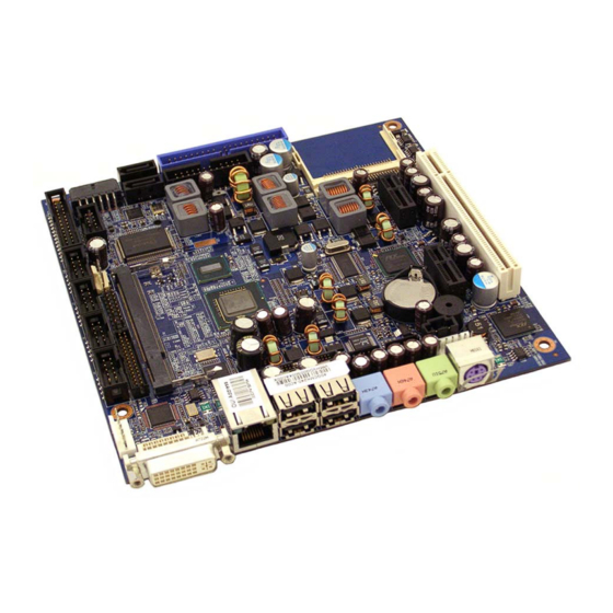
KTUS15 Family KTD-00774-0 Public User Manual Date: 2008-12-29 Page 21 of 61 Connector layout 4.1.1 KTUS15/mITX, Top-side SATA1 COMPACT FLASH SATA0 FRONTPNL PATA PRINTER USB6/7 COM4 PCI Slot 1 FAN_CPU PCIe x1 Slot 2 COM2 DDR2 SLOT Clr-CMOS COM3 FEATURE PCIe x1 Slot 1 COM1 AUDIO... -
Page 22: Ktus15/Mitx, Back-Side
KTUS15 Family KTD-00774-0 Public User Manual Date: 2008-12-29 Page 22 of 61 4.1.2 KTUS15/mITX, Back-side SDIO2 SDIO0... -
Page 23: Power Connector (Pwr)
KTUS15 Family KTD-00774-0 Public User Manual Date: 2008-12-29 Page 23 of 61 Power Connector (PWR) The KTUS15 boards are designed to be supplied from a wide-range single supply DC-supply: 5-25V DC +/-5%. Power Connector, PWR: Note Type Signal Signal Type Note +Vin +Vin... -
Page 24: Keyboard And Ps/2 Mouse Connectors (Kbd)
KTUS15 Family KTD-00774-0 Public User Manual Date: 2008-12-29 Page 24 of 61 Keyboard and PS/2 mouse connectors (KBD) Attachment of a keyboard or PS/2 mouse adapter can be done through the PS/2 mouse and keyboard connector (KBD). Both interfaces utilize open-drain signaling with on-board pull-up. The PS/2 mouse and keyboard is supplied from SB5V when in standby mode in order to enable keyboard or mouse activity to bring the system out from power saving states. -
Page 25: Display Connectors
DVI Connector (DVI-A), Analogue output The DVI-A connector only support DVI Analog output. For connecting a standard CRT (analogue) monitor to the DVI-A connector a DVI-CRT adapter can be used (Kontron P/N 822001). Female socket, front view Signal Description - DVI Connector: Pin No. -
Page 26: Dvi Connector (Dvi-D), Digital Output
KTUS15 Family KTD-00774-0 Public User Manual Date: 2008-12-29 Page 26 of 61 4.4.2 DVI Connector (DVI-D), Digital output The DVI-D connector only support DVI Digital output. Female socket, front view Signal Description - DVI Connector: Pin No. Signal Description Type Pull Up TMDS Data 2- Digital Red –... -
Page 27: Lvds Flat Panel Connector (Lvds)
KTUS15 Family KTD-00774-0 Public User Manual Date: 2008-12-29 Page 27 of 61 4.4.3 LVDS Flat Panel Connector (LVDS) Note Type Signal Signal Type Note Max. 0.5A +12V +12V Max. 0.5A Max. 0.5A +12V +12V Max. 0.5A Max. 0.5A +12V Max. 0.5A Max. -
Page 28: Pci-Express Connectors
KTUS15 Family KTD-00774-0 Public User Manual Date: 2008-12-29 Page 28 of 61 PCI-Express Connectors The KT boards contains two 1-lane (x1) PCI Express ports intended for an external PCI Express cards. The PCI Express port is compliant to the PCI Express* Base Specification revision 1.1. The two 1-lane (x1) PCI Express ports are supplied through a onboard 5-Lane/5-port PCI express switch. -
Page 29: Serial Ata Harddisk Interface
KTUS15 Family KTD-00774-0 Public User Manual Date: 2008-12-29 Page 29 of 61 Serial ATA harddisk interface The KTUS15 boards includes an onboard SATA interface depending on the configuration (refer to section KTUS15/mITX Board configurations). The SATA Host controller supports 2-port SATA II interface with data transfer rates of up to 3.0Gb/s (300MB/s). -
Page 30: Parallel Ata Harddisk Interface
KTUS15 Family KTD-00774-0 Public User Manual Date: 2008-12-29 Page 30 of 61 Parallel ATA harddisk interface The PATA Host Controller supports three types of data transfers: • Programmed I/O (PIO): Processor is in control of the data transfer. • Multi-word DMA (ATA-5): DMA protocol that resembles the DMA on the ISA bus. Allows transfer rates of up to 66 MB/s. -
Page 31: Ide Hard Disk Connector (Pata)
KTUS15 Family KTD-00774-0 Public User Manual Date: 2008-12-29 Page 31 of 61 4.7.1 IDE Hard Disk Connector (PATA) This connector can be used for connection of two primary IDE drives. Pull Pull Note Ioh/Iol Type Signal Signal Type Ioh/Iol Note RESET_P# DA10 DA11... -
Page 32: Cf Connector (Cf)
KTUS15 Family KTD-00774-0 Public User Manual Date: 2008-12-29 Page 32 of 61 4.7.2 CF Connector (CF) This connector is mounted on the topside of the KTUS15/mITX. The CF socket support DMA/UDMA modules up to UDMA2. NOTE: If the CF connector is used then only one PATA device is supported and only by use of 40-wire cable (not 80-wire cable). -
Page 33: Printer Port Connector (Printer)
KTUS15 Family KTD-00774-0 Public User Manual Date: 2008-12-29 Page 33 of 61 Printer Port Connector (PRINTER). The signal definition in standard printer port mode is as follows: Pull Pull Note Ioh/Iol Type Signal Signal Type Ioh/Iol Note (24)/24 OC(O) STB# AFD# OC(O) (24)/24... -
Page 34: Ktus15 Family
KTUS15 Family KTD-00774-0 Public User Manual Date: 2008-12-29 Page 34 of 61 Serial Ports Two or four RS232 serial ports are available on the KTUS15 boards depending on the configuration (refer to section KTUS15/mITX Board configurations). The typical interpretation of the signals in the COM ports is as follows: Signal Description Transmitte Data, sends serial data to the communication link. -
Page 35: Ethernet Connectors
KTUS15 Family KTD-00774-0 Public User Manual Date: 2008-12-29 Page 35 of 61 4.10 Ethernet connectors. The KTUS15 board support 1 channel of 10/100/1000Mb Ethernet using the Intel® 82574L PCI express LAN controller. In order to achieve the specified performance of the Ethernet port, Category 5 twisted pair cables must be used with 10/100MB and Category 5E, 6 or 6E with 1Gb LAN networks. -
Page 36: Usb Connector (Usb)
KTUS15 Family KTD-00774-0 Public User Manual Date: 2008-12-29 Page 36 of 61 4.11 USB Connector (USB) The KTUS15 boards ntains three Universal Host Controller Interface (UHCI) USB 1.1 controllers and an Enhanced Host Controller Interface (EHCI) USB 2.0 controller. A total of eight USB ports are supported. All eight of these ports are capable of highspeed data transfers up to 480 MB/s, and six of the ports are also capable of full-speed and low-speed signaling (USB Ports 0, 1, 2, 3, 4, 5). -
Page 37: Usb Connector 0/2 (Usb0/2)
KTUS15 Family KTD-00774-0 Public User Manual Date: 2008-12-29 Page 37 of 61 4.11.1 USB Connector 0/2 (USB0/2) Pull Pull Note Ioh/Iol Type Signal Signal Type Ioh/Iol Note 5V/SB5V /15K 0.25/2 USB0- USB0+ 0.25/2 /15K 5V/SB5V /15K 0.25/2 USB2- USB2+ 0.25/2 /15K Note 1: The 5V supply for the USB devices is on-board fused with a 2.0A reset-able fuse. -
Page 38: Usb Connector 6/7 (Usb6/7)
KTUS15 Family KTD-00774-0 Public User Manual Date: 2008-12-29 Page 38 of 61 4.11.3 USB Connector 6/7 (USB6/7) USB Ports 6 and 7 are are supplied on the internal USB6, USB7 pinrow connector. Pull Pull Note Ioh/Iol Type Signal Signal Type Ioh/Iol Note 5V/SB5V... -
Page 39: Audio Connector
KTUS15 Family KTD-00774-0 Public User Manual Date: 2008-12-29 Page 39 of 61 4.12 Audio Connector The onboard Audio circuit implements 7.1+2 Channel High Definition Audio, featuring ten 24-bit stereo DACs and two 20-bit stereo ADCs. The Audio signals are made available on the Frontpanel connectors (Line in / Line out / MIC) and the onboard AUDIO_HEAD and CDROM Audio input connectors. -
Page 40: Cd-Rom Audio Input (Cdrom)
KTUS15 Family KTD-00774-0 Public User Manual Date: 2008-12-29 Page 40 of 61 4.12.2 CD-ROM Audio input (CDROM) CD-ROM audio input may be connected to this connector. It may also be used as a secondary line-in signal. Signal Type Ioh/Iol Pull Note CD_Left CD_GND... -
Page 41: Audio Header (Audio_Head)
KTUS15 Family KTD-00774-0 Public User Manual Date: 2008-12-29 Page 41 of 61 4.12.3 AUDIO Header (AUDIO_HEAD) Pull Ioh/ Ioh/ Pull Note Type Signal Signal Type Note LFE-OUT CEN-OUT AAGND AAGND FRONT-OUT-L FRONT-OUT-R AAGND AAGND REAR-OUT-L REAR-OUT-R SIDE-OUT-L 11 12 SIDE-OUT-R AAGND 13 14 AAGND... -
Page 42: Fan Connectors, (Fan_Cpu)
KTUS15 Family KTD-00774-0 Public User Manual Date: 2008-12-29 Page 42 of 61 4.13 Fan connectors, (FAN_CPU) The FAN_CPU is used for connection of the FAN for the CPU or System. The 4pin header supports connection of 3-pin FANs, but it is recommended to use the 4-pin type for optimized FAN speed control. -
Page 43: The Clear Cmos Jumper, Clr-Cmos
KTUS15 Family KTD-00774-0 Public User Manual Date: 2008-12-29 Page 43 of 61 4.14 The Clear CMOS Jumper, Clr-CMOS. The Clr-CMOS Jumper is used to clear the CMOS content. ↑ CPU location ↑ No Jumper installed (Pin numbers) Jumper normal position •... -
Page 44: Tpm Connector (Unsupported)
KTUS15 Family KTD-00774-0 Public User Manual Date: 2008-12-29 Page 44 of 61 4.15 TPM connector (unsupported). Pull Pull Note Ioh/Iol Type Signal Signal Type Ioh/Iol Note LPC CLK LPC FRAME# LPC RST# LPC AD3 LPC AD2 +3V3 LPC AD1 LPC AD0 11 12 SMB_CLK 13 14... -
Page 45: Front Panel Connector (Frontpnl)
KTUS15 Family KTD-00774-0 Public User Manual Date: 2008-12-29 Page 45 of 61 4.16 Front Panel connector (FRONTPNL). Pull Pull Note Ioh/Iol Type Signal Signal Type Ioh/Iol Note USB13_5V USB13_5V USB1- USB3- USB1+ USB3+ LINE2-IN-L 11 12 HD_LED 13 14 SUS_LED 15 16 PWRBTN_IN# RSTIN#... -
Page 46: Feature Connector (Feature)
General Purpose Inputs / Output. These Signals may be controlled or monitored through GPIO0..7 the use of the KONTRON API (Application Programming Interface) available for WinXP and Win2000. FAN 3 speed control OUTput. This analogue voltage output signal can be set to output FAN3OUT voltages from 0 –... -
Page 47: Pci Slot Connector (Pci Slot 1)
KTUS15 Family KTD-00774-0 Public User Manual Date: 2008-12-29 Page 47 of 61 4.18 PCI Slot Connector (PCI Slot 1) Terminal Note Type Signal Signal Type Note -12V TRST# +12V INTA# INTB# INTC# INTD# REQ2# CLKC REQ3# +5V (I/O) GNT2# CLKD CLKA GNT3# RST#... -
Page 48: Signal Description -Pci Slot Connector
KTUS15 Family KTD-00774-0 Public User Manual Date: 2008-12-29 Page 48 of 61 4.18.1 Signal Description –PCI Slot Connector SYSTEM PINS Clock provides timing for all transactions on PCI and is an input to every PCI device. All other PCI signals, except RST#, INTA#, INTB#, INTC#, and INTD#, are sampled on the rising edge of CLK and all other timing parameters are defined with respect to this edge. - Page 49 KTUS15 Family KTD-00774-0 Public User Manual Date: 2008-12-29 Page 49 of 61 ARBITRATION PINS (BUS MASTERS ONLY) Request indicates to the arbiter that this agent desires use of the bus. This is a point to point signal. Every REQ# master has its own REQ# which must be tri-stated while RST# is asserted. Grant indicates to the agent that access to the bus has been granted.
-
Page 50: Ktus15 Pci Irq & Int Routing
KTUS15 Family KTD-00774-0 Public User Manual Date: 2008-12-29 Page 50 of 61 4.18.2 KTUS15 PCI IRQ & INT routing Board type Slot IDSEL INTA INTB INTC INTD KTUS15/mITX AD16 INT_PIRQ#A INT_PIRQ#B INT_PIRQ#C INT_PIRQ#D When using the 820982 “PCI Riser - Flex - 2slot w. arbiter” the lower slot has IDSEL / IRQs routed straight through and the top slot has the routing: IDSEL=AD30, INT_PIRQ#D, INT_PIRQ#A, INT_PIRQ#B, INT_PIRQ#C. -
Page 51: Onboard Connectors
22-23-2061 Molex 22-01-2065 CDROM Foxconn HF1104E Molex 50-57-9404 Molex 70543-0038 SATA0-1 Molex 67491-0020 Molex 67489-8005 Kontron KT 821035 (cable kit) Molex 43045-1201 Molex 43025-1200 KT 1022-6309 (cable kit Kontron for ATX) COM1, 2, 3, 4 Foxconn HL20051 Molex 90635-1103 Kontron... -
Page 52: System Ressources
KTUS15 Family KTD-00774-0 Public User Manual Date: 2008-12-29 Page 52 of 61 6. System Ressources Memory map Address range (hex) Size Description... -
Page 53: Pci Devices
KTUS15 Family KTD-00774-0 Public User Manual Date: 2008-12-29 Page 53 of 61 PCI devices Device Function Vendor Device IDSEL Chip Device Function... -
Page 54: Interrupt Usage
Onboard system parity errors and IOCHCHK signal activation Onboard Timer 0 Interrupt Onboard Keyboard Interrupt Used for Cascading IRQ8-IRQ15 May be used by onboard Serial Port A May be used by onboard Serial Port B / IrDA Port May be used by onboard Parallel Port Used by onboard Real Time Clock Alarm May be used by onboard P/S 2 support Used for Onboard co-processor support... -
Page 55: I/O Map
KTUS15 Family KTD-00774-0 Public User Manual Date: 2008-12-29 Page 55 of 61 I/O Map Address (hex) Size Description Notes:... -
Page 56: Dma Channel Usage
KTUS15 Family KTD-00774-0 Public User Manual Date: 2008-12-29 Page 56 of 61 DMA Channel Usage DMA Channel Number Data Width System Ressources 8 or 16 bits Available 8 or 16 bits Available 8 or 16 bits Available 8 or 16 bits Available 8 or 16 bits DMA Controller... -
Page 57: Overview Of Bios Features
7. Overview of BIOS features This Manual section details specific BIOS features for the KTUS15 boards. The KTUS15 boards are based on the AMI BIOS core version 8.10 with Kontron BIOS extensions. System Management BIOS (SMBIOS / DMI) SMBIOS is a Desktop Management Interface (DMI) compliant method for managing computers in a managed network. -
Page 58: Bios Configuration / Setup
KTUS15 Family KTD-00774-0 Public User Manual Date: 2008-12-29 Page 58 of 61 8. BIOS Configuration / Setup Introduction The BIOS Setup is used to view and configure BIOS settings for the KTUS15 board. The BIOS Setup is accessed by pressing the DEL key after the Power-On Self-Test (POST) memory test begins and before the operating system boot begins. -
Page 59: Ami Bios Beep Codes
KTUS15 Family KTD-00774-0 Public User Manual Date: 2008-12-29 Page 59 of 61 AMI BIOS Beep Codes Boot Block Beep Codes: Number of Description Beeps Insert diskette in floppy drive A: ‘AMIBOOT.ROM’ file not found in root directory of diskette in A: Base Memory error Flash Programming successful Floppy read error... -
Page 60: Os Setup
Use the Setup.exe files for all relevant drivers. The drivers can be found on KTUS15 Driver CD or they can be downloaded from the homepage http://www.kontron.com/ Note: When installing Intel ® Graphics drvers it is possible that the OS start up without any connected display(s) active. -
Page 61: Warranty
61 of 61 10. Warranty KONTRON Technology warrants its products to be free from defects in material and workmanship during the warranty period. If a product proves to be defective in material or workmanship during the warranty period, KONTRON Technology will, at its sole option, repair or replace the product with a similar product.
Need help?
Do you have a question about the KTUS15/mITX 1.6GHz Std and is the answer not in the manual?
Questions and answers