Table of Contents
Advertisement
Advertisement
Table of Contents

Subscribe to Our Youtube Channel
Related Manuals for Kontron KTA70M/mITX


Summary of Contents for Kontron KTA70M/mITX
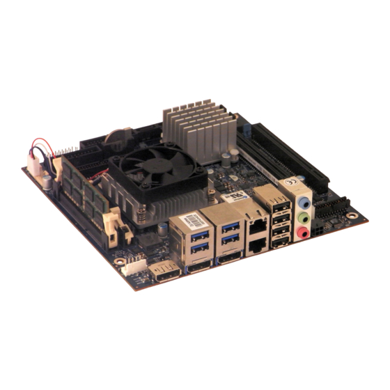
- Page 1 KTA70M/mITX KTD-N0861-B The pulse of innovation...
-
Page 2: Table Of Contents
Installing the Board ........................ 2 Requirements IEC60950 ......................3 System Specifications ................4 Component main data ......................4 KTA70M/mITX Block Diagram ..................... 8 Power Consumption ......................... 9 USB ports overview ........................ 11 Connectors Locations ................13 KTA70m/mITX Topview ......................13 KTA70m/mITX Bottomview ....................... - Page 3 North Bridge ..........................70 Boot ........................... 74 9.4.1 CSM parameters ........................... 76 Security ..........................77 Save & Exit ........................... 78 AMI BIOS Beep Codes ................79 Appendix: Mating Connectors ................80 Appendix: OS Setup ..................81 KTA70M/mITX Users Guide KTA70M/mITX Users Guide...
-
Page 4: Document Revision History
Copyright 2013, KONTRON Technology A/S, ALL RIGHTS RESERVED. No part of this document may be reproduced or transmitted in any form or by any means, electronically or mechani- cally, for any purpose without the express written permission of KONTRON Technology A/S. KTA70M/mITX Users Guide... -
Page 5: Trademark Acknowledgement
Brand and product names are trademarks or registered trademarks of their respective owners. Disclaimer KONTRON Technology A/S reserves the right to make changes without notice to any product, including circuits and/or software described or contained in this manual in order to improve design and/or performance. - Page 6 2. Driver Version numbers: Graphics, Network, and Audio etc. 3. Attached Hardware: Harddisks, CD-Rom, Display Panels etc. If the Kontron Technology product seems to be defect and you want to return it for repair, please follow the guide lines from the following page: http://kontron.com/services/rma-information/kontron-technology-a-s/...
- Page 7 General Information Warranty KONTRON Technology warrants its products to be free from defects in material and workmanship during the warranty period. If a product proves to be defective in material or workmanship during the warranty period KONTRON Technology will, at its sole option, repair or replace the product with a similar product.
-
Page 8: Introduction
Introduction Introduction This manual describes the KTA70M/mITX family of boards made by KONTRON Technology A/S. These board will also be denoted KTA70M within this Users Guide. The KTA70M family is based on AMD eTrinity platform: AMD BGA FP2 processor APU and AMD Fusion controller Hub A70M (Hudson M3) on a mini ITX form factor. -
Page 9: Installation Procedure
Installation Procedure Installing the Board To get the board running, follow these steps. If the board shipped from KONTRON has already components like RAM mounted, then relevant steps below can be skipped. 1. Turn off the PSU (Power Supply Unit) Warning: Turn off PSU (Power Supply Unit) befor configuring the board and do not hot plug power supply, otherwise components (RAM, LAN cards etc.) might get damaged. -
Page 10: Requirements Iec60950
Paristo voi räjähtää, jos se on virheellisesti asennettu. batterityp eller en ekvivalent typ som rekommenderas av Vaihda paristo ainoastaan lalteval- mistajan apparattillverkaren. Kassera använt batteri enligt suosittelemaan tyyppiln. Hävitä käytetty paristo fabrikantens instruktion. valmistajan ohjeiden mukaisesti. KTA70M/mITX Users Guide KTA70M/mITX Users Guide... -
Page 11: System Specifications
KTD-N0861-B Page 4 System Specification System Specifications Component main data The table below summarizes the features of the KTA70M/mITX embedded motherboards. Form factor mITX ( miniITX): 170,18 x 170,18 mm / 6,7 x 6,7” Processor AMD eTrinity FP2 processor: •... - Page 12 3x Audiojacks stack J40 (in REAR-IO area) Blue Line-In Green Speaker Pink Mic Audio Audio Pin header J41 Line-out Line-in Surround output: SIDE, LFE, CEN, BACK and FRONT Microphone: MIC1 and MIC2 CDROM in SPDIF (electrical Interface only) KTA70M/mITX Users Guide KTA70M/mITX Users Guide...
- Page 13 CAUTION: Danger of explosion if the battery is incorrectly replaced. Replace only with the same or equivalent type recommended by the manufacturer. Dispose of used batteries according to the manufacturer’s instructions. Speaker On-board Speaker Piezo On-board speaker (Electromagnetic Sound Generator like Hycom HY-05LF) KTA70M/mITX Users Guide KTA70M/mITX Users Guide...
- Page 14 -20°C – 70°C; lower limit of storage temperature is defined by specification restriction of on-board CR2032 battery. Board with battery has been verified for storage temperature down to -40°C by Kontron. 5% - 95% relative humidity (non-condensing) Electro Static Discharge (ESD) / Radiated Emissions (EMI): All Peripheral interfaces intended for connection to external equipment are ESD/ EMI protected.
-
Page 15: Kta70M/Mitx Block Diagram
KTD-N0861-B Page 8 System Specification KTA70M/mITX Block Diagram eTrinity APU 2x SODIMM DDR3 PCIe x8 (x16slot) Graphics Dual Channel 1067/1333 Processor 813pin uBGA 3x DP (DisplayPort 1.2) 4x USB3.0/USB2.0 1x PCIe x4 (x16 slot) 9x USB2.0 1x mPCIe w. USB (USB2.0) -
Page 16: Power Consumption
8. Tektronix TCPA300 9. Tektronix TCP312 10. Fluke 289 Note: The Power consumption of Monitor and HDDs is not included. Warning: Hot Plugging power supply is not supported. Hot plugging might damage the board. KTA70M/mITX Users Guide KTA70M/mITX Users Guide... - Page 17 Power consumption 3DMARK2005 ( first scene ) & CPUBURN 2534mA 30.41W Current draw Power consumption S3 Mode, Mean, No external load 77mA 0.93W Current draw Power consumption S4 Mode, Mean, No external load 55mA 0.66W KTA70M/mITX Users Guide KTA70M/mITX Users Guide...
-
Page 18: Usb Ports Overview
- the wires have the right diameter to withstand the maximum available current. - to enclosure of the peripheral device fulfills the fire-protecting conditions of IEC/EN 60950. KTA70M/mITX Users Guide KTA70M/mITX Users Guide... - Page 19 System Specification For USB2.0 cabling it is required to use only HiSpeed USB cable, specified in USB2.0 standard: For USB3.0 cabling it is required to use only HiSpeed USB cable, specified in USB3.0 standard: KTA70M/mITX Users Guide KTA70M/mITX Users Guide...
-
Page 20: Connectors Locations
Audio J41 Bp J33 (backside) (not mounted) Power J19 (Internal) USB12 J14 DP1 J43 USB10 J15 USB6 ETH1 LineIn Power J28 USB13 J14 USB11 J15 ETH2 USB7 LineOut (external) DP0 J4 DP2 J3 USB8 USB9 KTA70M/mITX Users Guide KTA70M/mITX Users Guide... -
Page 21: Kta70M/Mitx Bottomview
KTD-N0861-B Page 14 Connectors Location KTA70m/mITX Bottomview mSATA J39 mPCIe J38 HDT+ J32 Bp J33 (not mounted) (not mounted) KTA70M/mITX Users Guide KTA70M/mITX Users Guide... -
Page 22: Connector Signal Definitions
Iol: Typical current in mA flowing into an output pin from a VCC connected load while the output voltage has low level. The abbreviation tbd is used for specifications which are not available yet or which are not sufficiently specified by the component vendors. KTA70M/mITX Users Guide KTA70M/mITX Users Guide... -
Page 23: Rear Io Connectors
To protect the external power lines of peripheral devices make sure that - the wires have the right diameter to withstand the maximum available current. - to enclosure of the peripheral device fulfills the fire-protecting conditions of IEC/EN 60950. KTA70M/mITX Users Guide KTA70M/mITX Users Guide... - Page 24 2. All DP must be converted to DVI-D or HDMI via passive adapters like above adapters. 3. Two of the panels must have the same timing (as if two panels are of the exact same type). KTA70M/mITX Users Guide KTA70M/mITX Users Guide...
-
Page 25: Usb3.0 Connectors (Usb10/Usb11/Usb12/Usb13)(J15/J15/J14/J14)
USB Ports 12 and 13 (mounted on top of the DP#0 port): Note Type Signal Signal Type Note DSIO-3.3 USB12- USB12+ DSIO-3.3 5V/SB5V DSIO-3.3 RX12- TX12+ DSIO-3.3 DSIO-3.3 RX12+ TX12- DSIO-3.3 DSIO-3.3 USB13- USB13+ DSIO-3.3 5V/SB5V DSIO-3.3 RX13- TX13+ DSIO-3.3 RX13+ TX13- DSIO-3.3 KTA70M/mITX Users Guide KTA70M/mITX Users Guide... - Page 26 - the wires have the right diameter to withstand the maximum available current. - to enclosure of the peripheral device fulfills the fire-protecting conditions of IEC/EN 60950. KTA70M/mITX Users Guide KTA70M/mITX Users Guide...
-
Page 27: Ethernet Connectors (Eth1/Eth2) (J8)
MDI crossover mode: acts as the BI_DD+/- pair. MDI mode: fourth pair in 1000Base-T (i.e. the BI_DD+/- pair). MDI[3]+ / MDI[3]- MDI crossover mode: acts as the BI_DC+/- pair. Note: MDI = Media Dependent Interface. KTA70M/mITX Users Guide KTA70M/mITX Users Guide... -
Page 28: Usb X4 Stack Connector (Usb6/Usb7/Usb8/Usb9) (J20)
- the wires have the right diameter to withstand the maximum available current. - to enclosure of the peripheral device fulfills the fire-protecting conditions of IEC/EN 60950. KTA70M/mITX Users Guide KTA70M/mITX Users Guide... -
Page 29: Audio Interface (J40)
Microphone 1 - Left Shared with Audio Header MIC1-R Microphone 1 - Right Shared with Audio Header LINE1-L Line 1 signal - Left Shared with Audio Header LINE1-R Line 1 signal - Right Shared with Audio Header KTA70M/mITX Users Guide KTA70M/mITX Users Guide... -
Page 30: Dc Power External Connector (J28)
Rear IO Connectors DC Power External Connector (J28) The KTA70M/mITX board has an external power input connector for supplying voltage in the range from +11.4V to +12.6V. The power connector is a 4 pin Micro-Fit type Molex 0430450402 or similar. -
Page 31: Pin Connectors
Pin Connectors DC Power Internal Connector (J19) The KTA70M/mITX has an internal power input connector for supplying voltage in the range from +11.4V to +12.6V. The power connector is a 4 pin 12V ATX connector type Lotes ABA-POW-003-K02 or similar. -
Page 32: Audio Header Connector (J41)
LFE-OUT Subwoofer Speaker (Low Freq. Effect Out). No connection MIC1 MIC Input 1 LINE1 Line 1 signals F-SPDIF-OUT S/PDIF Output AAGND Audio Analogue ground Available cable kit: PN 821043 Cable, Audio Open-End (300 mm) KTA70M/mITX Users Guide KTA70M/mITX Users Guide... -
Page 33: Power Out Connector (J18)
- the wires have the right diameter to withstand the maximum available current. - to enclosure of the peripheral device fulfills the fire-protecting conditions of IEC/EN 60950. Available cable kit: PN 1027-3669 Cable Power Out KTA70M/mITX Users Guide KTA70M/mITX Users Guide... -
Page 34: Usb4/5 Connector (J16)
- the wires have the right diameter to withstand the maximum available current. - to enclosure of the peripheral device fulfills the fire-protecting conditions of IEC/EN 60950. Available cable kit: PN 821401 Bracket Dual USB Cable KTA70M/mITX Users Guide KTA70M/mITX Users Guide... -
Page 35: Jumper Area (J34, J35, J36, J37)
Don’t leave the Clear CMOS jumper in position 1-2, otherwise if power is disconnected, the battery will fully deplete within a few weeks. Warning Audio Short Circuit Test: is only used in manufacturing test. No jumper should be installed. KTA70M/mITX Users Guide KTA70M/mITX Users Guide... -
Page 36: Spi Connector (J21)
The ISOLATE# input, active low, is normally NC, but must be connected to GND when ISOLATE# loading SPI flash. Power Supply to the Motherboard must be turned off when loading SPI flash. The pull up resistor is connected via diode to 5VSB. KTA70M/mITX Users Guide KTA70M/mITX Users Guide... -
Page 37: Com1/Com2 (J23/J22)
Data Carrier Detect, indicates that the modem or data set has detected the data carrier. Ring Indicator, indicates that the modem has received a ringing signal from the telephone line. Available cable kit (DB9 adapter cables): PN 821017 - 100 mm or PN 821016 - 200 mm KTA70M/mITX Users Guide KTA70M/mITX Users Guide... -
Page 38: Lpc Connector (J29)
LPC CLK PWR LPC FRAME# LPC RST# LPC AD3 LPC AD2 +3V3 9 10 LPC AD1 LPC AD0 11 12 SMB_CLK 13 14 SMB_DATA SB3V3 15 16 LPC SERIRQ 17 18 CLKRUN# SUS_STAT# 19 20 KTA70M/mITX Users Guide KTA70M/mITX Users Guide... -
Page 39: Front Panel Connector (J5)
Analogue Ground for Audio Note: In order to meet the requirements of USB standard, the 5V input supply must be at least 5.00V. Available cable kit: PN 821042 Cable Front Panel Open-End, 300 mm KTA70M/mITX Users Guide KTA70M/mITX Users Guide... -
Page 40: Cpu/System Fan Connectors (J25, J24)
PWM is output signal used to control the fan speed (only for 4-wire Fans). Tarcho input signal is used to monitor the rotation speed RPM (Rotation Per Minute). Tacho Prepared for two pulses per turn. The CPU Fan is premounted on the KTA70M/mITX. PN 1052-6341 R-252F and R-460L versions. for R-460H version. -
Page 41: Feature Connector (J26)
43 44 25/25mA Notes: 1. Pull-up to SB3V3. 2. Pull-up to on-board Battery. 3. Not connected, used for onboard feature. 4. Not supported. Available cable kit: PN 1052-5885 Cable, Feature 44pol 1 to1, 300mm KTA70M/mITX Users Guide KTA70M/mITX Users Guide... - Page 42 Based on Maxim DS18B20, Accurate to ±0.5ºC over the range of -10ºC to +85ºC Feature connector 3.3V (Pin 9), GND (Pin 19) and GPIO16 (Pin 29) PN1053-4925 Cable Temperature Sensor - 44P, 400 mm KTA70M/mITX Users Guide KTA70M/mITX Users Guide...
- Page 43 ADC4/WUI28/GPI4 AI/IS/IS GPIO13 RI1#/WUI0/GPD0 IS/IS/IOS GPIO14 RI2#/WUI1/GPD1 IS/IS/IOS GPIO15 TMRI0/WUI2/GPC4 IS/IS/IOS GPIO16 TMRI1/WUI3/GPC6 IS/IS/IOS Optionally for Cable Temperature sensor GPIO17 L80HLAT/BAO/WUI24/GPE0 O4/O4/IS/IOS Reserved, used for Sync Feature Break-out board: PN 820978 Feature BOB (Break-Out-Board) KTA70M/mITX Users Guide KTA70M/mITX Users Guide...
-
Page 44: Kbd/Mse (J27)
Bi-directional clock signal used to strobe data/commands from/to the PC-AT keyboard. KBDDAT Bi-directional serial data line used to transfer data from or commands to the PC-AT keyboard. Available cable kit: PN 1053-2384 Bracket Cable 6-Pin to PS2-Kbd-Mse KTA70M/mITX Users Guide KTA70M/mITX Users Guide... -
Page 45: Slot Connectors (Pci-Express, Minipcie, Sata, Msata)
B24 A24 B25 A25 PEG_RXP[2] B26 A26 PEG_RXN[2] PEG_TXP[3] B27 A27 PEG_TXN[3] B28 A28 B29 A29 PEG_RXP[3] B30 A30 PEG_RXN[3] CLKREQ B31 A31 B32 A32 PEG_TXP[4] B33 A33 PEG_TXN[4] B34 A34 B35 A35 PEG_RXP[4] KTA70M/mITX Users Guide KTA70M/mITX Users Guide... - Page 46 B66 A66 B67 A67 B68 A68 B69 A69 B70 A70 B71 A71 B72 A72 B73 A73 B74 A74 B75 A75 B76 A76 B77 A77 B78 A78 B79 A79 B80 A80 CLKREQ B81 A81 B82 A82 KTA70M/mITX Users Guide KTA70M/mITX Users Guide...
-
Page 47: Pciex4 (J6)
B25 A25 PEG_RXP[2] B26 A26 PEG_RXN[2] PEG_TXP[3] B27 A27 PEG_TXN[3] B28 A28 B29 A29 PEG_RXP[3] B30 A30 PEG_RXN[3] CLKREQ B31 A31 B32 A32 B33 A33 B34 A34 B35 A35 B36 A36 B37 A37 B38 A38 KTA70M/mITX Users Guide KTA70M/mITX Users Guide... - Page 48 B66 A66 B67 A67 B68 A68 B69 A69 B70 A70 B71 A71 B72 A72 B73 A73 B74 A74 B75 A75 B76 A76 B77 A77 B78 A78 B79 A79 B80 A80 CLKREQ B81 A81 B82 A82 KTA70M/mITX Users Guide KTA70M/mITX Users Guide...
-
Page 49: Mpcie Connector (J38)
USB2- Diff. pair USB2 - DSIO-3.3 Ground USB2+ Diff. pair USB2 + 3.3V Power +3.3V Ground 3.3V Power +3.3V N.C. Ground N.C. N.C. N.C. N.C. 1.5V Power +1.5V N.C. Ground N.C. 3.3V Power +3.3V KTA70M/mITX Users Guide KTA70M/mITX Users Guide... -
Page 50: Sata0, Sata1, Sata2, Sata3, Sata4 (J12, J13, J9, J11, J10)
The S-ATA interface is available through standard L-type connector (7 pins). Header Signal Description Type Ground Transmit (positive) Transmit (negative) Ground Receive (negative) Receive (positive) Ground Available cable kit: PN 821035 Cable SATA 500mm KTA70M/mITX Users Guide KTA70M/mITX Users Guide... -
Page 51: Msata Connector (J39)
SATA_TX+ S-ATA transmit+ Ground Ground N.C. Ground N.C. 3.3V Power +3.3V Ground 3.3V Power +3.3V N.C. Ground N.C. N.C. N.C. N.C. 1.5V Power +1.5V N.C. Ground ® Sel_SATA# S-ATA identification I-1.8 3.3V Power +3.3V KTA70M/mITX Users Guide KTA70M/mITX Users Guide... -
Page 52: Bios
Black text for settings that cannot be changed via control keys. The following table describes the changeable settings: Feature Options Description System Language English (only English available) System Date MM/DD/YYYY Set the system date. System Time HH:MM:SS Set the system time. KTA70M/mITX Users Guide KTA70M/mITX Users Guide... -
Page 53: Advanced
The Advanced (main) menu contains only submenu selections which will be described in more details on the following pages. In order to make a selection of a submenu activated the ↑↓ keys until the requested submenu becomes white color, then activate the <Enter>. KTA70M/mITX Users Guide KTA70M/mITX Users Guide... -
Page 54: Advanced - Pci Subsystem Settings
Enabled Disabled PERR# Generation Enables or Disables PCI Device to Generate PERR#. Enabled Disabled SERR# Generation Enables or Disables PCI Device to Generate SERR#. Enabled Note: The selection in bold is the default selection. KTA70M/mITX Users Guide KTA70M/mITX Users Guide... -
Page 55: Pci Express Settings
Unpopulated Links [Keep Link ON] Enter: Select +/- : Change Opt. F1: General Help F2: Previous Values F3: Optimized Defaults F4: Save & Exit ESC: Exit Version 2.15.1227. Copyright © 2012 American Megatrends, Inc KTA70M/mITX Users Guide KTA70M/mITX Users Guide... - Page 56 ´Link Training´ bit in Link Status register. Value range from 10 to 1000uS. In order to save power, software will disable Keep Link ON Unpopulated Links unpopulated PCI Express links, if this option set Disabled to Disabled. KTA70M/mITX Users Guide KTA70M/mITX Users Guide...
-
Page 57: Advanced - Apci Settings
Suspend Disabled Select ACPI sleep state the system will enter ACPI Sleep State when the SUSPEND button is pressed. S3 only(Suspend to RAM) Disabled Lock Legacy Resources Enables or Disables Lock Legacy Resources. Enabled KTA70M/mITX Users Guide KTA70M/mITX Users Guide... -
Page 58: Advanced - Trusted Computing
State of Security Disable Take Ownership Device. TPM Clear Note: TPM State and Pending operation are only visible if Security Device Support is Enabled followed by Save and Exit. KTA70M/mITX Users Guide KTA70M/mITX Users Guide... -
Page 59: Advanced - Cpu Configuration
PState 0 – Pstate 4 Provide to adjust _PPC object. Disabled Enable/disable Ni-execute page protection NX Mode Function. Enabled Disabled SVM Mode Enable/disable CPU Virtualization. Enabled Auto CPB Mode Auto/disable CPB. Disabled Disabled C6 Mode Enable/disable C6. Enabled KTA70M/mITX Users Guide KTA70M/mITX Users Guide... -
Page 60: Node 0 Information
→← : Select Screen ↑↓ : Select Item Enter: Select +/- : Change Opt. F1: General Help F2: Previous Values F3: Optimized Defaults F4: Save & Exit ESC: Exit Version 2.15.1227. Copyright © 2012 American Megatrends, Inc KTA70M/mITX Users Guide KTA70M/mITX Users Guide... -
Page 61: Advanced - Ide Configuration
→← : Select Screen ↑↓ : Select Item Enter: Select +/- : Change Opt. F1: General Help F2: Previous Values F3: Optimized Defaults F4: Save & Exit ESC: Exit Version 2.15.1227. Copyright © 2012 American Megatrends, Inc KTA70M/mITX Users Guide KTA70M/mITX Users Guide... -
Page 62: Advanced - Usb Configuration
Auto reports itself to the Host Controller. ´Auto´ uses Device power-up delay default value: for a Root port it is 100 ms, for a Hub Manual port the delay is taken from Hub descriptor. KTA70M/mITX Users Guide KTA70M/mITX Users Guide... -
Page 63: Advanced - Super Io Configuration
F1: General Help F2: Previous Values F3: Optimized Defaults F4: Save & Exit ESC: Exit Version 2.15.1227. Copyright © 2012 American Megatrends, Inc The 2 submenus are shown and described on the following pages. KTA70M/mITX Users Guide KTA70M/mITX Users Guide... -
Page 64: Serial Port 1 Configuration
Enable or Disable Serial Port (COM) Enabled Auto IO=3F8h; IRQ=4; Change Settings (Note1) IO=3F8h; IRQ=3,4,5,6,7,10,11,12; Select an optimal setting for Super IO device. IO=2F8h; IRQ=3,4,5,6,7,10,11,12; IO=3E8h; IRQ=3,4,5,6,7,10,11,12; IO=2E8h; IRQ=3,4,5,6,7,10,11,12; Note1: only if Serial Port = Enabled KTA70M/mITX Users Guide KTA70M/mITX Users Guide... -
Page 65: Serial Port 2 Configuration
Enable or Disable Serial Port (COM) Enabled Auto IO=2F8h; IRQ=3; IO=3F8h; IRQ=3,4,5,6,7,10,11,12; Select an optimal setting for Super Change Settings (Note1) IO device. IO=2F8h; IRQ=3,4,5,6,7,10,11,12; IO=3E8h; IRQ=3,4,5,6,7,10,11,12; IO=2E8h; IRQ=3,4,5,6,7,10,11,12; Note1: only if Serial Port = Enabled KTA70M/mITX Users Guide KTA70M/mITX Users Guide... -
Page 66: Advanced - Hardware Health Configuration
+/- : Change Opt. F1: General Help 12V Supply : 11.70 V F2: Previous Values F3: Optimized Defaults Watchdog Function F4: Save & Exit ESC: Exit Version 2.15.1227. Copyright © 2012 American Megatrends, Inc KTA70M/mITX Users Guide KTA70M/mITX Users Guide... - Page 67 Note8: Seconds, use digit keys to enter value. Value 0 means Watchdog is disabled. Refer to “KT-API-V2 User Manual” to control the Watchdog via API or refer to “KT-API-V2 User Manual DLL” how to control Watchdog via Windows DLL. KTA70M/mITX Users Guide KTA70M/mITX Users Guide...
-
Page 68: Advanced - Lan Configuration
Version 2.15.1227. Copyright © 2012 American Megatrends, Inc Function Selection Description Disabled Enabled ETH1 Configuration (Upper) Control of Ethernet Devices and PXE boot. With PXE boot Disabled ETH2 Configuration (Lower) Enabled Control of Ethernet Devices and PXE boot. With PXE boot KTA70M/mITX Users Guide KTA70M/mITX Users Guide... -
Page 69: Advanced - Pci-E Port
NB PCIE Connect Type (Display device). Travis DP-to-LVDS Nutmeg DP-to-VGA (# = 0, 1, 2, 3) Single Link DVI-I CRT (VGA) LVDS Auto Detect Disabled Deafult Settings Defaults: Port 0, 1, 2 = DP and Port 3 = Disabled. KTA70M/mITX Users Guide KTA70M/mITX Users Guide... -
Page 70: Network Stack
PXE boot option will not be created. (Note1) Disabled Ipv6 PXE Support Enabled Enable Ipv6 PXE Boot Support. If disabled IPV6 PXE boot option will not be created. (Note1) Disabled Note1: Only if Network stack = Enabled. KTA70M/mITX Users Guide KTA70M/mITX Users Guide... -
Page 71: Chipset
→← : Select Screen ↑↓ : Select Item Enter: Select +/- : Change Opt. F1: General Help F2: Previous Values F3: Optimized Defaults F4: Save & Exit ESC: Exit Version 2.15.1227. Copyright © 2012 American Megatrends, Inc KTA70M/mITX Users Guide KTA70M/mITX Users Guide... -
Page 72: South Bridge
Please find description of the “SB SATA Configuration”, “SB USB Configuration” and “SB HD Azalia Configuration” on the following pages. Function Selection Description Power Off Select AC Power state when power is re-applied Power On Restore AC Power Loss after a power failure. Last State KTA70M/mITX Users Guide KTA70M/mITX Users Guide... -
Page 73: Sb Sata Configuration
RAID >AHCI as ID 7804 AHCI OnChip SATA Type Legacy IDE IDE ->AHCI AHCI as ID 7804 IDE->AHCI as ID 7804 Legacy mode OnChip IDE mode Native mode Disabled SATA IDE Combined Mode Enabled KTA70M/mITX Users Guide KTA70M/mITX Users Guide... - Page 74 F4: Save & Exit XHCI0 PORT 0 [Enabled] ESC: Exit XHCI0 PORT 1 [Enabled] XHCI1 PORT 0 [Enabled] XHCI1 PORT 1 [Enabled] ░ ░ Version 2.15.1227. Copyright © 2012 American Megatrends, Inc Scroll to see further settings. KTA70M/mITX Users Guide KTA70M/mITX Users Guide...
-
Page 75: Sb Usb Configuration
USB PORT 0 - 9 Enabled Disabled XHCI0 PORT 0 Enabled Disabled XHCI0 PORT 1 Enabled Disabled XHCI1 PORT 0 Enabled Disabled XHCI1 PORT 1 Enabled Disabled USB PORT FL0 Enabled Disabled USB PORT FL1 Enabled KTA70M/mITX Users Guide KTA70M/mITX Users Guide... - Page 76 Auto: The insertions of audio jacks are auto Disabled determined. Audio Jack Sensing Auto Disabled: Driver assumes that all jacks are inserted (useful when using the Audio pinrow) Disabled Azalia Snoop Enable or disable internal HDMI codec for Azalia. Enabled KTA70M/mITX Users Guide KTA70M/mITX Users Guide...
-
Page 77: North Bridge
→← : Select Screen ↑↓ : Select Item Enter: Select +/- : Change Opt. F1: General Help F2: Previous Values F3: Optimized Defaults F4: Save & Exit ESC: Exit Version 2.15.1227. Copyright © 2012 American Megatrends, Inc KTA70M/mITX Users Guide KTA70M/mITX Users Guide... -
Page 78: Graphics Configuration
Switch Brightness Control Mode between Brightness Control Mode VBIOS/DRIVER. Switch Control by Driver Auto Enable Integrated Graphics controller. Integrated Graphics Disabled Force Disabled PCIe speed power policy Performance PSPP Policy Balanced-High Balanced-Low Power Saving KTA70M/mITX Users Guide KTA70M/mITX Users Guide... -
Page 79: Memory Configuration
1066MHz Memory Clock 1333MHz 1600MHz 1866MHz Disabled Memory Hole Remapping. Memory Hole Remapping Enabled Disabled Bank Interleaveing Bank Interleaveing Enabled Disabled Channel Interleaving Channel Interleaving Enabled Disabled Enable/Disable Memory Clear function. Memory Clear Enabled KTA70M/mITX Users Guide KTA70M/mITX Users Guide... - Page 80 →← : Select Screen ↑↓ : Select Item Enter: Select +/- : Change Opt. F1: General Help F2: Previous Values F3: Optimized Defaults F4: Save & Exit ESC: Exit Version 2.15.1227. Copyright © 2012 American Megatrends, Inc KTA70M/mITX Users Guide KTA70M/mITX Users Guide...
-
Page 81: Boot
F2: Previous Values F3: Optimized Defaults F4: Save & Exit ESC: Exit Version 2.15.1227. Copyright © 2012 American Megatrends, Inc Note: When pressing <F7> while booting it is possible manually to select boot device. KTA70M/mITX Users Guide KTA70M/mITX Users Guide... - Page 82 Immediate: execute the trap right away. Postponed Postponed: execute the trap during legacy boot. Boot Option #1 (list of bootable devices) Sets the system boot order. Note: To enter number use digit keys and/or +/- keys. KTA70M/mITX Users Guide KTA70M/mITX Users Guide...
-
Page 83: Csm Parameters
Controls the execution of UEFI and Legacy UEFI only policy Video OpROM. Legacy only For PCI devices other than Network, Mass UEFI OpROM Other PCI device ROM storage or Video defines which OpROM to priority Legacy OpROM launch. KTA70M/mITX Users Guide KTA70M/mITX Users Guide... -
Page 84: Security
Secure Boot is possible only if System runs in Enabled User Mode. Secure Boot mode selector. Standard Standard: fixed Secure boot policy. Secure Boot Mode Custom Custom: changeable Image Execution policy and Secure Boot Key databases. KTA70M/mITX Users Guide KTA70M/mITX Users Guide... -
Page 85: Save & Exit
Save the Changes done so far as User Defaults. Restore User Defaults Restore the User Defaults to all the setup options. Selection table of bootable devices. When selected system will boot on (possible list of boot devices) selected device. KTA70M/mITX Users Guide KTA70M/mITX Users Guide... -
Page 86: Ami Bios Beep Codes
This will reveal the malfunctioning card. If the system video adapter is an add-in card, replace or reset the video adapter. If the video adapter is an integrated part of the system board, the board may be faulty. KTA70M/mITX Users Guide KTA70M/mITX Users Guide... -
Page 87: Appendix: Mating Connectors
1x PN 821043 Cable, Audio Open-End 6x PN 821035 Cable, SATA, 500mm 1x PN 1052-5814 Cable, ATX Power for KTA70M 1x PN 1027-3669 Cable Power Out 1x PN 821401 Cable+Bracket, USB, 10poled 1x PN 1052-5818 SW,Man&Driver CD,KTA70M/KTA75 KTA70M/mITX Users Guide KTA70M/mITX Users Guide... -
Page 88: Appendix: Os Setup
Use the Setup.exe files for all relevant drivers. The drivers can be found on KTA7x Driver CD or they can be downloaded from the homepage http://www.kontron.com/ For some OS like Win7 when installing OS via USB DVD, USB Keyboard/Mouse, please connect the USB DVD, USB Keyboard/Mouse to USB2.0 ports only or disable USB3.0 in BIOS.
Need help?
Do you have a question about the KTA70M/mITX and is the answer not in the manual?
Questions and answers