Table of Contents
Advertisement
Advertisement
Table of Contents

Subscribe to Our Youtube Channel
Related Manuals for MPP Solar PIP-HS


Summary of Contents for MPP Solar PIP-HS
- Page 1 PIP-HS 1- 5KVA INVERTER / CHARGER User Manual VERSION 1.7...
-
Page 2: Table Of Contents
Table Of Contents ABOUT THIS MANUAL ............................. 1 Purpose ................................1 Scope ................................1 SAFETY INSTRUCTIONS ..........................1 INTRODUCTION ............................... 2 Features ................................2 Basic System Architecture ..........................2 Product Overview ............................. 3 INSTALLATION ..............................4 Unpacking and Inspection..........................4 Preparation .............................. -
Page 3: About This Manual
ABOUT THIS MANUAL Purpose This manual describes the assembly, installation, operation and troubleshooting of this unit. Please read this manual carefully before installations and operations. Keep this manual for future reference. Scope This manual provides safety and installation guidelines as well as information on tools and wiring. SAFETY INSTRUCTIONS WARNING: This chapter contains important safety and operating instructions. -
Page 4: Introduction
INTRODUCTION This is a multi-function inverter/charger, combining functions of inverter, solar charger and battery charger to offer uninterruptible power support with portable size. Its comprehensive LCD display offers user-configurable and easy-accessible button operation such as battery charging current, AC/solar charger priority, and acceptable input voltage based on different applications. -
Page 5: Product Overview
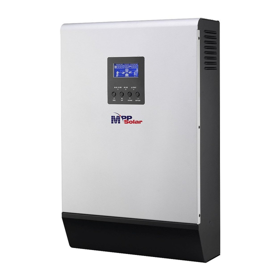
Product Overview 4KVA/5KVA single model 1KVA model 4KVA/5KVA parallel model 1. LCD display 2. Status indicator 3. Charging indicator 4. Fault indicator 5. Function buttons 6. Power on/off switch 2KVA/3KVA model 7. AC input 8. AC output NOTE: For parallel model installation and operation, 9. -
Page 6: Installation
INSTALLATION Unpacking and Inspection Before installation, please inspect the unit. Be sure that nothing inside the package is damaged. You should have received the following items inside of package: The unit x 1 User manual x 1 Communication cable x 1 ... -
Page 7: Battery Connection
Install the unit by screwing three screws. It’s recommended to use M4 or M5 screws. Battery Connection CAUTION: For safety operation and regulation compliance, it’s requested to install a separate DC over-current protector or disconnect device between battery and inverter. It may not be requested to have a disconnect device in some applications, however, it’s still requested to have over-current protection installed. - Page 8 capacity battery for 1-3KVA model and at least 200Ah capacity battery for 4KVA/5KVA model. 3. Insert the ring terminal of battery cable flatly into battery connector of inverter and make sure the bolts are tightened with torque of 2-3 Nm. Make sure polarity at both the battery and the inverter/charge is correctly connected and ring terminals are tightly screwed to the battery terminals.
-
Page 9: Ac Input/Output Connection
AC Input/Output Connection CAUTION!! Before connecting to AC input power source, please install a separate AC breaker between inverter and AC input power source. This will ensure the inverter can be securely disconnected during maintenance and fully protected from over current of AC input. The recommended spec of AC breaker is 10A for 1KVA, 20A for 2KVA, 32A for 3KVA , 40A for 4KVA and 50A for 5KVA. - Page 10 WARNING: Be sure that AC power source is disconnected before attempting to hardwire it to the unit. 4. Then, insert AC output wires according to polarities indicated on terminal block and tighten terminal screws. Be sure to connect PE protective conductor ( ) first.
-
Page 11: Pv Connection (Only Apply For The Model With Solar Charger)
PV Connection (Only apply for the model with solar charger) CAUTION: Before connecting to PV modules, please install separately a DC circuit breaker between inverter and PV modules. WARNING! All wiring must be performed by a qualified personnel. WARNING! It's very important for system safety and efficient operation to use appropriate cable for PV module connection. -
Page 12: Final Assembly
Maximum Power (Pmax) 260W Max. PV module numbers in series Max. Power Voltage Vmpp(V) 30.9V 1 30.9 x 1 ≒ 30 ~ 32 Max. Power Current Impp(A) 8.42A PV module numbers in parallel 6 50 A / 8.42 Open Circuit Voltage Voc(V) 37.7V Total PV module numbers... -
Page 13: Communication Connection
Communication Connection Please use supplied communication cable to connect to inverter and PC. Insert bundled CD into a computer and follow on-screen instruction to install the monitoring software. For the detailed software operation, please check user manual of software inside of CD. Dry Contact Signal There is one dry contact (3A/250VAC) available on the rear panel. -
Page 14: Operation
OPERATION Power ON/OFF Once the unit has been properly installed and the batteries are connected well, simply press On/Off switch (located on the button of the case) to turn on the unit. Operation and Display Panel The operation and display panel, shown in below chart, is on the front panel of the inverter. It includes three indicators, four function keys and a LCD display, indicating the operating status and input/output power information. -
Page 15: Lcd Display Icons
LCD Display Icons Icon Function description Input Source Information Indicates the AC input. Indicates the PV input Indicate input voltage, input frequency, PV voltage, battery voltage and charger current. Configuration Program and Fault Information Indicates the setting programs. Indicates the warning and fault codes. Warning: flashing with warning code. - Page 16 In battery mode, it will present battery capacity. Load Percentage Battery Voltage LCD Display < 1.717V/cell 1.717V/cell ~ 1.8V/cell Load >50% 1.8 ~ 1.883V/cell > 1.883 V/cell < 1.817V/cell 1.817V/cell ~ 1.9V/cell 50%> Load > 20% 1.9 ~ 1.983V/cell > 1.983 <...
-
Page 17: Setting Programs
LCD Setting After pressing and holding ENTER button for 3 seconds, the unit will enter setting mode. Press “UP” or “DOWN” button to select setting programs. And then, press “ENTER” button to confirm the selection or ESC button to exit. Setting Programs: Program Description... - Page 18 50A (default) 60A (Only for 4K/5K models) 70A (Only for 4K/5K models) 80A (Only for 4K/5K models) 90A (Only for 4K/5K models) 100A (Only for 4K/5K models) 110A (Only for 4K/5K models) Appliances (default) If selected, acceptable AC input voltage range will be within 90-280VAC.
- Page 19 Available options in 1K model: 20A (default) Available options in 2K/3K model: 30A (default) Maximum utility charging current Available options in 4K/5K model: Note: If setting value in program 02 is smaller than that in program in 11, the inverter will apply charging 30A (default) current from program 02 for utility charger.
- Page 20 24.0V 24.5V 25.0V 25.5V Available options in 4K/5K model: 46V (default) Available options in 1K model: Battery fully charged 12.0V 12.3V 12.5V Setting voltage point back 12.8V 13.0V to battery mode when selecting “SBU priority” or “Solar first” in program 01. 13.3V 13.5V (default) 13.8V...
- Page 21 14.3V 14.5V Available options in 2K/3K model: Battery fully charged 24.5V 25.5V 26.5V 27V (default) Setting voltage point back 27.5V to battery mode when selecting “SBU priority” or “Solar first” in program 01. 28.5V Available options in 4K/5K model: Battery fully charged 54V (default)
- Page 22 If this inverter/charger is working in Line, Standby or Fault mode, charger source can be programmed as below: Solar first Solar energy will charge battery as first priority. Utility will charge battery only when solar energy is not available. Utility first Utility will charge battery as first priority.
- Page 23 Bypass disable Bypass enable Overload bypass: (default) When enabled, the unit will transfer to line mode if overload occurs in battery mode. Record enable Record disable (default) Record Fault code 1KVA default setting: 14.1V 2K/3KVA default setting: 28.2V Bulk charging voltage (C.V voltage) 4K/5KVA default setting: 56.4V If self-defined is selected in program 5, this program can...
- Page 24 1KVA default setting: 10.5V 2K/3KVA default setting: 21.0V 4K/5KVA default setting: 42.0V Low DC cut-off voltage If self-defined is selected in program 5, this program can be set up. Setting range is from 10.0V to 12.0V for 1K model, 20.0V to 24.0V for 2K/3K model and 40.0V to 48.0V for 4K/5K model.
-
Page 25: Display Setting
Display Setting The LCD display information will be switched in turns by pressing “UP” or “DOWN” key. The selectable input voltage, input frequency, PV voltage, charging current, information is switched as below order: battery voltage, output voltage, output frequency, load percentage, load in Watt, load in VA, load in Watt, DC discharging current, main CPU Version and second CPU Version. - Page 26 Load percent=70% Load percentage When connected load is lower than 1kVA, load in VA will present xxxVA like below chart. Load in VA When load is larger than 1kVA (≧1KVA), load in VA will present x.xkVA like below chart. When load is lower than 1kW, load in W will present xxxW like below chart.
-
Page 27: Operating Mode Description
Secondary CPU version 00003.03 Secondary CPU version checking Operating Mode Description Operation mode Description LCD display Charging by utility and PV energy. Standby mode / Power saving mode Charging by utility. Note: *Standby mode: The inverter is No output is supplied by the not turned on yet but at this unit but it still can charge time, the inverter can charge... - Page 28 Operation mode Description LCD display No charging. PV energy and utility can Fault mode charge batteries. Note: *Fault mode: Errors are caused Utility can power loads when by inside circuit error or external Power from utility the unit starts up without reasons such as over battery.
-
Page 29: Fault Reference Code
Fault Reference Code Fault Code Fault Event Icon on Fan is locked when inverter is off. Over temperature Battery voltage is too high Battery voltage is too low Output short circuited or over temperature is detected by internal converter components. Output voltage is abnormal. -
Page 30: Specifications
SPECIFICATIONS Table 1 Line Mode Specifications INVERTER MODEL 1KVA 2KVA 3KVA 4KVA 5KVA Input Voltage Waveform Sinusoidal (utility or generator) Nominal Input Voltage 230Vac 170Vac± 7V (UPS); Low Loss Voltage 90Vac± 7V (Appliances) 180Vac± 7V (UPS); Low Loss Return Voltage 100Vac±... -
Page 31: Table 2 Inverter Mode Specifications
Table 2 Inverter Mode Specifications INVERTER MODEL 1KVA 2KVA 3KVA 4KVA 5KVA Rated Output Power 1KVA/0.8KW 2KVA/1.6KW 3KVA/2.4KW 4KVA/3.2KW 5KVA/4KW Pure Sine Wave Output Voltage Waveform 230Vac± 5% Output Voltage Regulation 50Hz Output Frequency Peak Efficiency Overload Protection 5s@≥150% load; 10s@110%~150% load 2* rated power for 5 seconds Surge Capacity Nominal DC Input Voltage... -
Page 32: Table 3 Charge Mode Specifications
Table 3 Charge Mode Specifications INVERTER MODEL 1KVA 2KVA 3KVA 4KVA 5KVA Charging Algorithm 3-Step Utility Charging Mode 20/30Amp 2/10/20/30/40/50/60Amp AC Charging Current 10/20Amp =230Vac) =230Vac) Flooded Battery 14.6 29.2 58.4 Bulk Charging AGM / Gel Voltage 14.1 28.2 56.4 Battery Floating Charging Voltage 13.5Vdc... -
Page 33: Trouble Shooting
TROUBLE SHOOTING Problem LCD/LED/Buzzer Explanation / Possible cause What to do Unit shuts down LCD/LEDs and buzzer automatically will be active for 3 The battery voltage is too low 1. Re-charge battery. during startup seconds and then (<1.91V/Cell) 2. Replace battery. process. -
Page 34: Appendix: Approximate Back-Up Time Table
Appendix: Approximate Back-up Time Table Model Load (VA) Backup Time @ 12Vdc 100Ah (min) Backup Time @ 12Vdc 200Ah (min) 1610 1KVA 1000 Model Load (VA) Backup Time @ 24Vdc 100Ah (min) Backup Time @ 24Vdc 200Ah (min) 1610 1000 2KVA 1200 1400... - Page 35 Model Load (VA) Backup Time @ 48Vdc 100Ah (min) Backup Time @ 48Vdc 200Ah (min) 1288 1000 1500 2000 2500 5KVA 3000 3500 4000 4500 5000 Note: Backup time depends on the quality of the battery, age of battery and type of battery. Specifications of batteries may vary depending on different manufacturers.
Need help?
Do you have a question about the PIP-HS and is the answer not in the manual?
Questions and answers