
Related Manuals for MPP Solar PIP-1212MS


Summary of Contents for MPP Solar PIP-1212MS
- Page 1 PIP-1212HS, 1212MS (1.5kva 12v) INVERTER / CHARGER User Manual *with built-in 40A MPPT or 50A PWM solar charger VERSION 1.0...
-
Page 2: Table Of Contents
Table Of Contents ABOUT THIS MANUAL ............................. 1 Purpose ................................1 Scope ................................1 SAFETY INSTRUCTIONS ..........................1 INTRODUCTION ............................... 2 Features ................................2 Basic System Architecture ..........................2 Product Overview ............................. 3 Unpacking and Inspection ..........................4 Preparation............................... 4 Mounting the Unit ............................. -
Page 3: About This Manual
ABOUT THIS MANUAL Purpose This manual describes the assembly, installation, operation and troubleshooting of this unit. Please read this manual carefully before installations and operations. Keep this manual for future reference. Scope This manual provides safety and installation guidelines as well as information on tools and wiring. SAFETY INSTRUCTIONS WARNING: This chapter contains important safety and operating instructions. -
Page 4: Introduction
INTRODUCTION This is a multi-function inverter/charger, combining functions of inverter, solar charger and battery charger to offer uninterruptible power support with portable size. Its comprehensive LCD display offers user-configurable and easy-accessible button operation such as battery charging current, AC/solar charger priority, and acceptable input voltage based on different applications. -
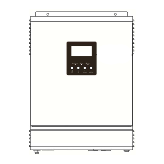
Page 5: Product Overview
Product Overview 1. LCD display 2. Status indicator 3. Charging indicator 4. Fault indicator 5. Function buttons 6. Power on/off switch 7. AC input 8. AC output 9. PV input 10. Battery input 11. Circuit breaker 12. USB communication port 13. -
Page 6: Unpacking And Inspection
INSTALLATION Unpacking and Inspection Before installation, please inspect the unit. Be sure that nothing inside the package is damaged. You should have received the following items inside of package: The unit x 1 User manual x 1 USB Communication cable x 1 ... -
Page 7: Battery Connection
Install the unit by screwing three screws. Battery Connection CAUTION: For safety operation and regulation compliance, it’s requested to install a separate DC over-current protector or disconnect device between battery and inverter. It may not be requested to have a disconnect device in some applications, however, it’s still requested to have over-current protection installed. -
Page 8: Ac Input/Output Connection
WARNING: Shock Hazard Installation must be performed with care due to high battery voltage in series. CAUTION!! Do not place anything between the flat part of the inverter terminal and the ring terminal. Otherwise, overheating may occur. CAUTION!! Do not apply anti-oxidant substance on the terminals before terminals are connected tightly. - Page 9 WARNING: Be sure that AC power source is disconnected before attempting to hardwire it to the unit. 4. Then, insert AC output wires according to polarities indicated on terminal block and tighten terminal screws. Be sure to connect PE protective conductor ( ) first.
-
Page 10: Pv Connection
PV Connection CAUTION: Before connecting to PV modules, please install separately a DC circuit breaker between inverter and PV modules. WARNING! All wiring must be performed by a qualified personnel. PV Module Selection: (Only for the model with built-in PWM solar charger) WARNING! It's very important for system safety and efficient operation to use appropriate cable for PV module connection. -
Page 11: Final Assembly
PV Module Selection: (Only for the model with built-in MPPT solar charger) When selecting proper PV modules, please be sure to consider below parameters: 3. Open circuit Voltage (Voc) of PV modules not exceeds max. PV array open circuit voltage of inverter. 4. -
Page 12: Dry Contact Signal
Dry Contact Signal There is one dry contact (3A/250VAC) available on the rear panel. It could be used to deliver signal to external device when battery voltage reaches warning level. Unit Status Condition Dry contact port: NC & C NO & C Power Off Unit is off and no output is powered. -
Page 13: Operation
OPERATION Power ON/OFF Once the unit has been properly installed and the batteries are connected well, simply press On/Off switch (located on the button of the case) to turn on the unit. Operation and Display Panel The operation and display panel, shown in below chart, is on the front panel of the inverter. It includes three indicators, four function keys and a LCD display, indicating the operating status and input/output power information. -
Page 14: Lcd Display Icons
LCD Display Icons Icon Function description Input Source Information Indicates the AC input. Indicates the PV input Indicate input voltage, input frequency, PV voltage, battery voltage and charger current. Configuration Program and Fault Information Indicates the setting programs. Indicates the warning and fault codes. Warning: flashing with warning code. - Page 15 Voltage mode Bottom three bars will be on and the top > 2.167 V/cell bar will flash. Floating mode. Batteries are fully charged. 4 bars will be on. Battery level icon will present battery capacity when unit is discharged. Load Percentage Battery Voltage LCD Display <...
-
Page 16: Lcd Setting
LCD Setting After pressing and holding ENTER button for 3 seconds, the unit will enter setting mode. Press “UP” or “DOWN” button to select setting programs. And then, press “ENTER” button to confirm the selection or ESC button to exit. Setting Programs: Program Description... - Page 17 220Vac 230V (Default) Output voltage 240Vac 50Hz (default) 60Hz Output frequency Saving mode disable If disabled, no matter connected (default) load is low or high, the on/off status of inverter output will not be Power saving mode effected. enable/disable Saving mode enable If enabled, the output of inverter will be off when connected load is pretty low or not detected.
- Page 18 If this inverter/charger is working in Battery mode or Power saving mode, only solar energy can charge battery. Solar energy will charge battery if it's available and sufficient. Maximum charging current: 60A (default) For unit with MPPT solar charger, To configure total charging setting range is from 10A to 100A.
- Page 19 3 Step Auto No CV charging time 10min 20min 40min 60min CV charging time setting 90min 120min 150min 180min 210min 240min 12V model default setting: 14.1V 24V model default setting: 28.2V Bulk charging voltage (C.V voltage) If self-defined is selected in program 14, this program can be set up.
- Page 20 If self-defined is selected in program 14, this program can be set up. Setting range is from 12.0V to 15.3V for 12Vdc model and 24.0V to 30.6V for 24Vdc model. Increment of each click is 0.1V. 12V model default setting: 10.2V 24V model default setting: 20.4V Low DC cut off battery voltage setting...
- Page 21 25.0V 25.5V Available options for 12V models: Battery fully charged 12.0V 12.3V 12.5V 12.8V 13.0V 13.3V 13.5V (default) 13.8V 14.0V Setting voltage point back to battery mode when selecting “SBU priority” or 14.3V 14.5V “Solar first” in program 01. Available options for 24V models: Battery fully charged 24.5V 25.5V...
- Page 22 27.5V 28.5V Return to default If selected, no matter how users display screen (default) switch display screen, it will automatically return to default display screen (Input voltage /output voltage) after no button is Auto return to default display screen pressed for 1 minute. Stay at latest screen If selected, the display screen will stay at latest screen user finally...
-
Page 23: Display Setting
Display Setting The LCD display information will be switched in turns by pressing “UP” or “DOWN” key. The selectable information is switched as below order: input voltage/output voltage, input frequency, PV voltage, charging current, output frequency, load percentage, load in VA, load in Watt, battery voltage/DC discharging current, main CPU Version and secondary CPU Version. - Page 24 When connected load is lower than 1kVA, load in VA will present xxxVA like below chart. Load in VA When load is larger than 1kVA (≧1KVA), load in VA will present x.xkVA like below chart. When load is lower than 1kW, load in W will present xxxW like below chart.
-
Page 25: Operating Mode Description
Operating Mode Description Operation mode Description LCD display Charging by utility and PV energy. Standby mode / Power saving mode/ Fault mode Note: *Standby mode: The inverter is not turned on yet but at this Charging by utility. time, the inverter can charge battery without AC output. -
Page 26: Fault Reference Code
Fault Reference Code Fault Code Fault Event Icon on Fan is locked when inverter is off. Over temperature Battery voltage is too high Output short circuited. Output voltage is too high. Overload time out Bus voltage is too high Bus soft start failed Over current or surge Bus voltage is too low Inverter soft start failed... -
Page 27: Specifications
SPECIFICATIONS Table 1 Line Mode Specifications INVERTER MODEL 1.5K-12V / 1.5K-24V / 3K-24V Input Voltage Waveform Sinusoidal (utility or generator) Nominal Input Voltage 220/230/240Vac 170Vac±7V (UPS); Low Loss Voltage 90Vac±7V (Appliances) 180Vac±7V (UPS); Low Loss Return Voltage 100Vac±7V (Appliances) High Loss Voltage 280Vac±7V High Loss Return Voltage 270Vac±7V... - Page 28 Table 2 Inverter Mode Specifications Inverter Mode Inverter Model 1.5K-12V 1.5K-24V 3K-24V Rated Output Power 1500VA/1200W 3000VA/2400W Output Voltage Waveform Pure Sine Wave Output Voltage Regulation 220Vac/230Vac/240Vac±5% Output Frequency 50Hz Peak Efficiency Overload Protection 5s@≥150% load; 10s@110%~150% load Surge Capacity 2 x rated power for 5sec Nominal DC Voltage 12Vdc...
- Page 29 Table 3 Charge Mode Specifications INVERTER MODEL 1.5K-12V 1.5K-24V / 3K-24V Charging Algorithm 3-Step Utility Charging Mode AC Charging Current 2/10/20/30/40/50/60Amp (@V =230Vac) Flooded Battery 14.6Vdc 29.2Vdc Bulk Charging Voltage AGM / Gel Battery 14.1Vdc 28.2Vdc Floating Charging Voltage 13.5Vdc 27.0Vdc Charging Curve PWM Solar Charging Mode...
-
Page 30: Trouble Shooting
TROUBLE SHOOTING Problem LCD/LED/Buzzer Explanation / Possible cause What to do Unit shuts down LCD/LEDs and buzzer automatically will be active for 3 The battery voltage is too low 1. Re-charge battery. during startup seconds and then (<1.91V/Cell) 2. Replace battery. process.
Need help?
Do you have a question about the PIP-1212MS and is the answer not in the manual?
Questions and answers