Table of Contents
Advertisement
Quick Links
Advertisement
Table of Contents

Related Manuals for MPP Solar PIP3024GEW


Summary of Contents for MPP Solar PIP3024GEW
- Page 1 User Manual PIP3024GEW/PIP5048GEW INVERTER / CHARGER Version: 1.1...
-
Page 2: Table Of Contents
Table Of Contents ABOUT THIS MANUAL ............................1 Purpose ................................1 Scope ................................1 SAFETY INSTRUCTIONS ........................... 1 INTRODUCTION ..............................2 Features ................................2 Basic System Architecture ..........................2 Product Overview ............................. 3 INSTALLATION ..............................4 Unpacking and Inspection..........................4 Preparation .............................. -
Page 3: About This Manual
ABOUT THIS MANUAL Purpose This manual describes the assembly, installation, operation and troubleshooting of this unit. Please read this manual carefully before installations and operations. Keep this manual for future reference. Scope This manual provides safety and installation guidelines as well as information on tools and wiring. SAFETY INSTRUCTIONS WARNING: This chapter contains important safety and operating instructions. -
Page 4: Introduction
INTRODUCTION This is a multi-function inverter/charger, combining functions of inverter, solar charger and battery charger to offer uninterruptible power support with portable size. Its comprehensive LCD display offers user-configurable and easy-accessible button operation such as battery charging current, AC/solar charger priority, and acceptable input voltage based on different applications. -
Page 5: Product Overview
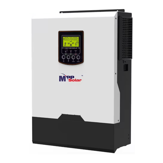
Product Overview PIP3024GEW PIP5048GEW 1. LCD display 2. Status indicator 3. Charging indicator 4. Fault indicator 5. Function buttons 6. Power on/off switch 7. AC input 8. AC output 9. PV input 10. Battery input 11. RS-232 communication port 12. BMS communication port 13. -
Page 6: Installation
DC Fuse x 1 (Only for PIP5048GEW model) Preparation Before connecting all wirings, please take off bottom cover by removing screws as shown below. PIP3024GEW model PIP5048GEW model Mounting the Unit Consider the following points before selecting where to install: Do not mount the inverter on flammable construction materials. -
Page 7: Battery Connection
For PIP3024GEW model, refer to recommended battery spec table to purchase separately two ring terminals and battery wires. Assemble two ring terminals with battery wires based on recommended battery cable and terminal size as grounding cable. - Page 8 Recommended tool: #2 Pozi Screwdriver For PIP3024GEW model, secure assembled ring terminals to the battery terminal block with the bolts properly tightened. Refer to battery cable size for torque value. Make sure polarity at both the battery and the inverter is correctly connected and ring terminals are secured to the battery terminals.
-
Page 9: Ac Input/Output Connection
To reduce risk of injury, please use the proper recommended cable size as below. Suggested cable requirement for AC wires Cable (mm Model Gauge Torque Value PIP3024GEW 14 AWG 0.6 Nm PIP5048GEW 10 AWG 1.2 Nm Please follow below steps to implement AC input/output connection: 1. - Page 10 ) first. →Ground (yellow-green) L→LINE (brown or black) N→Neutral (blue) PIP3024GEW model PIP5048GEW model WARNING: Be sure that AC power source is disconnected before attempting to hardwire it to the unit. 4. Then, insert AC output wires according to polarities indicated on terminal block and tighten terminal screws.
-
Page 11: Pv Connection
Take 250Wp PV module as an example. After considering above two parameters, the recommended module configurations are listed as below table. Solar Panel Spec. SOLAR INPUT (reference) (PIP3024GEW model: Min in serial: 3 pcs, max. in serial: 12 Q'ty of Total input - 250Wp pcs;... -
Page 12: Final Assembly
Connect negative pole (-) of connection wire to negative pole (-) of PV input connector. Screw two wires tightly in clockwise direction. Recommended tool: 4mm blade screwdriver PIP3024GEW model PIP5048GEW model Final Assembly After connecting all wirings, please put bottom cover back by screwing screws as shown below. -
Page 13: Communication Options
Communication Options Serial Connection Please use the supplied serial cable to connect between the inverter and your PC. Install the monitoring software from the bundled CD and follow the on-screen instructions to complete your installation. For detailed software operation, refer to the software user manual on the bundled CD. Wi-Fi Connection Wi-Fi transmitter can enable wireless communication between off-grid inverters and monitoring platform. -
Page 14: Operation
OPERATION Power ON/OFF Side view of unit Once the unit has been properly installed and the batteries are connected well, simply press On/Off switch (located on the button of the case) to turn on the unit. Operation and Display Panel The operation and display panel, shown in below chart, is on the front panel of the inverter. -
Page 15: Lcd Display Icons
LCD Display Icons Icon Function description Input Source Information Indicates the AC input. Indicates the PV input Indicate input voltage, input frequency, PV voltage, charger current, charger power, battery voltage. Configuration Program and Fault Information Indicates the setting programs. Indicates the warning and fault codes. Warning: flashing with warning code. - Page 16 In battery mode, it will present battery capacity. Load Percentage Battery Voltage LCD Display < 1.85V/cell 1.85V/cell ~ 1.933V/cell Load >50% 1.933V/cell ~ 2.017V/cell > 2.017V/cell < 1.892V/cell 1.892V/cell ~ 1.975V/cell Load < 50% 1.975V/cell ~ 2.058V/cell > 2.058V/cell Load Information Indicates overload.
-
Page 17: Lcd Setting
LCD Setting After pressing and holding ENTER button for 3 seconds, the unit will enter setting mode. Press “UP” or “DOWN” button to select setting programs. And then, press “ENTER” button to confirm the selection or ESC button to exit. Setting Programs: Program Description... - Page 18 User-Defined If “User-Defined” is selected, battery charge voltage and low DC cut-off voltage can be set up in program 26, 27 and 29. Pylontech battery If selected, programs of 02, 26, 27 and 29 will be automatically set up. No need for further setting. WECO battery If selected, programs of 02, 12, 26, 27 and 29 will be...
- Page 19 240V Available options in PIP3024GEW model 40A (default) Setting range is 2A, then from 10A Maximum utility charging current to 80A. Increment of each click is 10A. Note: If setting value in program 02 is smaller than Available options in PIP5048GEW model:...
- Page 20 SOC 80% (default for If any types of lithium battery is Lithium) selected in program 05, setting value will change to SOC automatically. Adjustable range is 10% to 100%. Increment of each click is 5%. If this inverter/charger is working in Line, Standby or Fault mode, charger source can be programmed as below: Solar first Solar energy will charge battery as...
- Page 21 Bulk charging voltage (C.V voltage) If self-defined is selected in program 5, this program can be set up. Setting range is from 25.0V to 31.0V for PIP3024GEW model and 48.0V to 61.0V for PIP5048GEW model. Increment of each click is 0.1V.
- Page 22 PIP3024GEW default setting: 29.2V PIP5048GEW default setting: 58.4V Battery equalization voltage Setting range is from 25.0V to 31.0V for PIP3024GEW models and 48.0V to 61.0V for PIP5048GEW model. Increment of each click is 0.1V. 60min (default) Setting range is from 5min to 900min.
-
Page 23: Display Setting
Display Setting The LCD display information will be switched in turns by pressing “UP” or “DOWN” key. The selectable information is switched as following order in listed table. Selectable information LCD display Input Voltage=230V, output voltage=230V Input voltage/Output voltage (Default Display Screen) Input frequency=50Hz Input frequency PV voltage=260V... - Page 24 AC and PV charging current=50A PV charging current=50A Charging current AC charging current=40A AC and PV charging power=500W PV charging power=500W Charging power AC charging power=500W Battery voltage=25.5V, output voltage=230V Battery voltage and output voltage...
- Page 25 Output frequency=50Hz Output frequency Load percent=70% Load percentage When connected load is lower than 1kVA, load in VA will present xxxVA like below chart. Load in VA When load is larger than 1kVA (≧1KVA), load in VA will present x.xkVA like below chart. When load is lower than 1kW, load in W will present xxxW like below chart.
-
Page 26: Operating Mode Description
Battery voltage=25.5V, discharging current=1A Battery voltage/DC discharging current Main CPU version 00014.04 Main CPU version checking Secondary CPU version 00001.00 Secondary CPU version checking. Operating Mode Description Operation mode Description LCD display Charging by utility and PV energy. Charging by utility. Standby mode Note: No output is supplied by the... - Page 27 Operation mode Description LCD display Fault mode Charging by PV energy. Note: *Fault mode: Errors are PV energy and utility can caused by inside circuit error charge batteries. or external reasons such as No charging. over temperature, output short circuited and so on. Charging by utility and PV energy.
-
Page 28: Battery Equalization Description
Operation mode Description LCD display PV energy will supply power to the loads and charge battery at the same time. The unit will provide output Power from battery only. Battery Mode power from battery and PV power. Power from PV energy only. Battery Equalization Description Equalization function is added into charge controller. -
Page 29: Fault Reference Code
Equalize charging time and timeout In Equalize stage, the controller will supply power to charge battery as much as possible until battery voltage raises to battery equalization voltage. Then, constant-voltage regulation is applied to maintain battery voltage at the battery equalization voltage. The battery will remain in the Equalize stage until setting battery equalized time is arrived. -
Page 30: Warning Indicator
Fault Code Fault Event Icon on Overload time out Bus voltage is too high Bus soft start failed Over current or surge Bus voltage is too low Inverter soft start failed Over DC voltage in AC output Current sensor failed Output voltage is too low PV voltage is over limitation Warning Indicator... -
Page 31: Clearance And Maintenance For Anti-Dust Kit
CLEARANCE AND MAINTENANCE FOR ANTI-DUST KIT Overview Every inverter is already installed with anti-dusk kit from factory. This kit keeps dusk from your inverter and increases product reliability in harsh environment. Clearance and Maintenance Step 1: Please loosen the screw in counterclockwise direction on the top of the inverter. Step 2: Then, dustproof case can be removed and take out air filter foam as shown in below chart. -
Page 32: Specifications
SPECIFICATIONS Table 1 Line Mode Specifications INVERTER MODEL PIP3024GEW PIP5048GEW Input Voltage Waveform Sinusoidal (utility or generator) Nominal Input Voltage 230Vac 170Vac± 7V (UPS); Low Loss Voltage 90Vac± 7V (Appliances) 180Vac± 7V (UPS); Low Loss Return Voltage 100Vac± 7V (Appliances) High Loss Voltage 280Vac±... - Page 33 Table 2 Inverter Mode Specifications INVERTER MODEL PIP3024GEW PIP5048GEW Rated Output Power 3KVA/3KW 5KVA/5KW Pure Sine Wave Output Voltage Waveform 230Vac± 5% Output Voltage Regulation 50Hz Output Frequency Peak Efficiency Overload Protection 5s@≥130% load; 10s@105%~130% load 2* rated power for 5 seconds...
- Page 34 Table 3 Charge Mode Specifications Utility Charging Mode INVERTER MODEL PIP3024GEW PIP5048GEW Charging Algorithm 3-Step AC Charging Current (Max) 80Amp (@V =230Vac) 100Amp Flooded Battery 29.2 58.4 Bulk Charging Voltage AGM / Gel Battery 28.2 56.4 Floating Charging Voltage 27Vdc...
-
Page 35: Trouble Shooting
TROUBLE SHOOTING Problem LCD/LED/Buzzer Explanation / Possible cause What to do Unit shuts down LCD/LEDs and buzzer automatically will be active for 3 The battery voltage is too low 1. Re-charge battery. during startup seconds and then (<1.91V/Cell) 2. Replace battery. process. -
Page 36: Appendix I: Bms Communication Installation
Appendix I: BMS Communication Installation 1. Introduction If connecting to lithium battery, it is recommended to purchase a custom-made RJ45 communication cable. Please check with your dealer or integrator for details. This custom-made RJ45 communication cable delivers information and signal between lithium battery and the inverter. - Page 37 Dip Switch: There are 4 Dip Switches that sets different baud rate and battery group address. If switch position is turned to the “OFF” position, it means “0”. If switch position is turned to the “ON” position, it means “1”.
- Page 38 Note for parallel system: 1. Only support common battery installation. 2. Use custom-made RJ45 cable to connect any inverter (no need to connect to a specific inverter) and Lithium battery. Simply set this inverter battery type to “LIB” in LCD program 5. Others should be “USE”. Step 3: Turn the breaker switch “ON".
- Page 39 PYLONTECH After configuration, please install LCD panel with inverter and Lithium battery with the following steps. Step 1. Use custom-made RJ45 cable to connect inverter and Lithium battery. Step 2. Switch on Lithium battery. Step 3. Press more than three seconds to start Lithium battery. Output power is ready. Step 4.
- Page 40 WECO Step 1. Use a custom-made RJ45 cable to connect inverter and Lithium battery. Step 2. Switch on Lithium battery. Step 3. Turn on the inverter. Step 4. Be sure to select battery type as “WEC” in LCD program 5. If communication between the inverter and battery is successful, the battery icon on LCD display will “flash”.
- Page 41 Step 2. Open DC isolator and switch on Lithium battery. Step 3. Turn on the inverter. Step 4. Be sure to select battery type as “SOL” in LCD program 5. If communication between the inverter and battery is successful, the battery icon on LCD display will “flash”.
- Page 42 5. Code Reference Related information code will be displayed on LCD screen. Please check inverter LCD screen for the operation. Code Description If battery status is not allowed to charge and discharge after the communication between the inverter and battery is successful, it will show code 60 to stop charging and discharging battery.
-
Page 43: Appendix Ii: The Wi-Fi Operation Guide In Remote Panel
Appendix II: The Wi-Fi Operation Guide in Remote Panel 1. Introduction Wi-Fi module can enable wireless communication between off-grid inverters and monitoring platform. Users have complete and remote monitoring and controlling experience for inverters when combining Wi-Fi module with WatchPower APP, available for both iOS and Android based device. All data loggers and parameters are saved in iCloud. - Page 44 Then, a “Registration success” window will pop up. Tap “Go now” to continue setting local Wi-Fi network connection. Step 2: Local Wi-Fi Module Configuration Now, you are in “Wi-Fi Config” page. There are detailed setup procedure listed in “How to connect?” section and you may follow it to connect Wi-Fi.
- Page 45 Step 3: Wi-Fi Network settings icon to select your local Wi-Fi router name (to access the internet) and enter password. Step 4: Tap “Confirm” to complete the Wi-Fi configuration between the Wi-Fi module and the Internet. If the connection fails, please repeat Step 2 and 3. Diagnose Function If the module is not monitoring properly, please tap “...
- Page 46 2-3. Login and APP Main Function After finishing the registration and local Wi-Fi configuration, enter registered name and password to login. Note: Tick “Remember Me” for your login convenience afterwards. Overview After login is successfully, you can access “Overview” page to have overview of your monitoring devices, including overall operation situation and Energy information for Current power and Today power as below diagram.
- Page 47 Devices Tap the icon (located on the bottom) to enter Device List page. You can review all devices here by adding or deleting Wi-Fi Module in this page. Add device Delete device (swipe left) icon on the top right corner and manually enter part number to add device. This part number label is pasted on the bottom of remote LCD panel.
- Page 48 2-4. Device List In Device List page, you can pull down to refresh the device information and then tap any device you want to check up for its real-time status and related information as well as to change parameter settings. Please refer to the parameter setting list.
- Page 49 【Battery Mode】 Inverter will power the load from the batter with or without PV charging. Only PV source can charge battery. Device Alarm and Name Modification In this page, tap the icon on the top right corner to enter the device alarm page. Then, you can review alarm history and detailed information.
- Page 50 【Rated Information】displays information of Nominal AC voltage, Nominal AC current, Rated battery voltage, Nominal output voltage, Nominal output frequency, Nominal output current, Nominal output apparent power and Nominal output active power. Please slide up to see more rated information. 【History】displays the record of unit information and setting timely. 【Wi-Fi Module Information】displays of Wi-Fi Module PN, status and firmware version.
- Page 51 Item Description Battery Battery type: To set connected battery type. parameter Battery cut-off To set the battery stop discharging voltage or SOC. setting voltage/SOC Please see product manual for the recommended voltage or SOC range based on connected battery type. Back to grid When “SBU”...
Need help?
Do you have a question about the PIP3024GEW and is the answer not in the manual?
Questions and answers