Table of Contents
Advertisement
Quick Links
Advertisement
Table of Contents

Related Manuals for MPP Solar PIP3624MT


Summary of Contents for MPP Solar PIP3624MT
- Page 1 User Manual PIP3624MT/PIP5648MT SOLAR INVERTER / CHARGER Version: 1.0...
-
Page 2: Table Of Contents
Table Of Contents ABOUT THIS MANUAL ........................1 Purpose ..............................1 Scope ..............................1 SAFETY INSTRUCTIONS ........................1 INTRODUCTION ..........................2 Features ............................... 2 Basic System Architecture ........................2 Product Overview ..........................3 INSTALLATION ..........................4 Unpacking and Inspection ........................4 Preparation ............................ -
Page 3: About This Manual
ABOUT THIS MANUAL Purpose This manual describes the assembly, installation, operation and troubleshooting of this unit. Please read this manual carefully before installations and operations. Keep this manual for future reference. Scope This manual provides safety and installation guidelines as well as information on tools and wiring. SAFETY INSTRUCTIONS All safety instructions in this document must be read, understood and WARNING:... -
Page 4: Introduction
INTRODUCTION This is a multi-function inverter, combining functions of inverter, solar charger and battery charger to offer uninterruptible power support in a single package. The comprehensive LCD display offers user-configurable and easy-accessible button operations such as battery charging current, AC or solar charging priority, and acceptable input voltage based on different applications. -
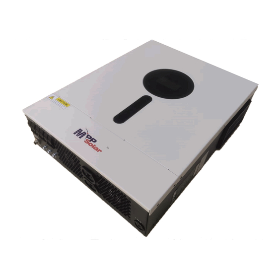
Page 5: Product Overview
Product Overview 1. LCD display 2. Function buttons with status indication 3. Power on/off switch 4. AC input 5. AC output 6. PV input 7. Battery input 8. Circuit breaker 9. USB communication port 10. RS-232 communication port... -
Page 6: Installation
INSTALLATION Unpacking and Inspection Before installation, please inspect the content. Be sure that nothing inside the package is damaged. You should have received the following items inside the package: Inverter x 1 User manual x 1 RS232 Communication cable x 1 ... -
Page 7: Battery Connection
PIP3624MT model and 200Ah capacity battery for PIP5648MT model. 2. Prepare four battery wires for PIP3624MT model and two or four battery wires for PIP5648MT model depending on cable size (refer to recommended cable size table). Apply ring terminals to your battery wires... - Page 8 Refer to battery cable size for torque value. Make sure polarity at both the battery and the inverter is correctly connected and ring terminals are secured to the battery terminals. PIP3624MT / PIP5648MT PIP5648MT WARNING: Shock Hazard Installation must be performed with care due to high battery voltage in series.
-
Page 9: Ac Input/Output Connection
To reduce risk of injury, please use the proper recommended cable size as below. Suggested cable requirement for AC wires Cable (mm Model Gauge Torque Value PIP3624MT 12 AWG 1.2 Nm PIP5648MT 10 AWG 1.2 Nm Please follow these steps to implement AC input/output connection: 1. -
Page 10: Pv Connection
Model Wire Size Cable (mm Torque value(max) PIP3624MT/PIP5648MT 1 x 12AWG 1.2 Nm WARNING: Because this inverter is non-isolated, are accepted: single crystalline, poly crystalline with class A-rated and CIGS modules. To avoid any malfunctions, do not connect any PV modules with possible current leakage to the inverter. - Page 11 Take the 250Wp PV module as an example. After considering above two parameters, the recommended module configurations are listed in the table below. Solar Panel Spec. SOLAR INPUT Total input Q'ty of panels (reference) Min in series: 2 pcs, max. in series: 12 pcs. power - 250Wp 2pcs in series...
-
Page 12: Final Assembly
Final Assembly After connecting all wirings, put the bottom cover back by fixing four screws as shown below. Communication Connection Please use supplied communication cable to connect to inverter and PC. Insert bundled CD into a computer and follow on-screen instruction to install the monitoring software. For the detailed software operation, please check user manual of software inside of CD. -
Page 13: Operation
OPERATION Power ON/OFF Once the unit has been properly installed and the batteries are connected well, simply press On/Off switch (located on the side of the inverter) to turn on the unit. Operation and Display Panel The operation and the LCD module, shown in the chart below, includes four touchable buttons with status indication and a LCD display, indicating the operating status and input/output power information. -
Page 14: Lcd Display Icons
LCD Display Icons Icon Function description Input Source Information Indicates the AC input. Indicates the PV input Indicate input voltage, input frequency, PV voltage, charger current, charger power, battery voltage. Configuration Program and Fault Information Indicates the setting programs. Indicates the warning and fault codes. Warning: flashing with warning code. -
Page 15: Lcd Setting
In battery mode, it will present battery capacity. Load Percentage Battery Voltage LCD Display < 1.85V/cell 1.85V/cell ~ 1.933V/cell Load >50% 1.933V/cell ~ 2.017V/cell > 2.017V/cell < 1.892V/cell 1.892V/cell ~ 1.975V/cell Load < 50% 1.975V/cell ~ 2.058V/cell > 2.058V/cell Load Information Indicates overload. - Page 16 Setting Programs: Progra Description Selectable option Escape Exit setting mode Utility will provide power to the Utility first (default) loads as first priority. Solar and battery energy will provide power to the loads only when utility power is not available. Solar energy provides power to the loads as first priority.
- Page 17 11, the 10A. inverter will apply charging current from program 02 for utility charger. Available options in PIP3624MT model: 23.0V (default) Setting range is from 22V to 25.5V. Increment of each click is 0.5V. Setting voltage point back to...
- Page 18 Bypass enable Overload bypass: When enabled, the unit will transfer to line mode if overload occurs in battery mode. Record enable (default) Record disable Record Fault code PIP3624MT default setting: 28.2V Bulk charging voltage (C.V voltage) PIP5648MT default setting: 56.4V...
- Page 19 If self-defined is selected in program 5, this program can be set up. Setting range is from 25.0V to 31.5V for PIP3624MT model and 48.0V to 61.0V for PIP5648MT model. Increment of each click is 0.1V. PIP3624MT default setting: 27.0V PIP5648MT default setting: 54.0V...
-
Page 20: Display Setting
Low DC cut off voltage on second output If “User-defined” is selected in program 05, this setting range is from 21.0V to 31.5V for PIP3624MT model and from 42.0V to 61.0V for 56KW model. Increment of each click is 0.1V. Disable (Default) Setting range is disable and then from 0 min to 990 min. - Page 21 Selectable information LCD display Input Voltage=230V, output voltage=230V Input voltage/Output voltage (Default Display Screen) Input frequency=50Hz Input frequency PV voltage=260V PV voltage PV current = 2.5A PV current PV power = 500W PV power AC and PV charging current=50A Charging Current PV charging current=50A...
- Page 22 AC charging current=50A Charging current AC and PV charging power=500W PV charging power=500W Charging power AC charging power=500W Battery voltage=25.5V, output voltage=230V Battery voltage and output voltage Output frequency=50Hz Output frequency Load percent=70% Load percentage...
- Page 23 When connected load is lower than 1kVA, load in VA will present xxxVA like below chart. Load in VA When load is larger than 1kVA (≧1KVA), load in VA will present x.xkVA like below chart. When load is lower than 1kW, load in W will present xxxW like below chart.
-
Page 24: Operating Mode Description
Operating Mode Description Operation mode Description LCD display Charging by utility and PV energy. Charging by utility. Standby mode Note: No output is supplied by the *Standby mode: The inverter unit but it still can charge is not turned on yet but at this batteries. - Page 25 If “solar first” is selected as output source priority and battery is not connected, solar energy and the utility will provide the loads. Power from utility. Power from battery and PV energy. PV energy will supply power to the loads and charge battery at the same time.
-
Page 26: Battery Equalization Description
Battery Equalization Description Battery equalization function is built into the charge controller. It reverses the buildup of negative chemical effects such as stratification, a condition where acid concentration is greater at the bottom of the battery than at the top. Equalization also helps to remove sulfate crystals that may have built up on the plates. If left unchecked, this condition, called sulfation, will reduce the overall capacity of the battery. -
Page 27: Fault Reference Code
However, in Equalize Mode, if the battery equalization timer runs out and the battery voltage doesn’t recover to the battery equalization voltage point, the charge controller will extend the battery equalized time until battery voltage achieves equalization voltage. If the battery voltage is still lower than equalization voltage when the extension runs out, the charge controller will stop equalization and return to the floating charging stage. -
Page 28: Warning Indicator
Warning Indicator Warning Warning Event Audible Alarm Icon flashing Code Beep three times every Fan is locked when inverter is on. second Over temperature None Battery is over-charged Beep once every second Low battery Beep once every second Overload Beep once every 0.5 second Output power derating Beep twice every 3 seconds PV energy is low. -
Page 29: Clearance And Maintenance For Anti-Dust Kit
CLEARANCE AND MAINTENANCE FOR ANTI-DUST KIT Overview Every inverter is already installed with anti-dusk kit from factory. Inverter will automatically detect this kit and activate internal thermal sensor to adjust internal temperature. This kit also keeps dusk from your inverter and increases product reliability in harsh environment. -
Page 30: Specifications
SPECIFICATIONS Table 1 Line Mode Specifications MODEL PIP3624MT PIP5648MT Input Voltage Waveform Sinusoidal (utility or generator) Nominal Input Voltage 230Vac 170Vac± 7V (UPS); Low Loss Voltage 90Vac± 7V (Appliances) 180Vac± 7V (UPS); Low Loss Return Voltage 100Vac± 7V (Appliances) High Loss Voltage 280Vac±... - Page 31 Table 2 Inverter Mode Specifications MODEL PIP5648MT PIP3624MT Rated Output Power 3.6KVA/3.6KW 5.6KVA/5.6KW Pure Sine Wave Output Voltage Waveform 230Vac± 5% Output Voltage Regulation 50Hz Output Frequency Peak Efficiency Overload Protection 5s@≥130% load; 10s@105%~130% load 2* rated power for 5 seconds...
- Page 32 Table 3 Charge Mode Specifications Utility Charging Mode MODEL PIP5648MT PIP3624MT Charging Current (UPS) 100Amp(@V =230Vac) @ Nominal Input Voltage Flooded Battery 29.2 58.4Vdc Bulk Charging Voltage AGM / Gel Battery 28.2 56.4Vdc Floating Charging Voltage 27Vdc 54Vdc Charging Algorithm 3-Step 2.43Vdc (2.35Vdc)
-
Page 33: Trouble Shooting
TROUBLE SHOOTING Problem LCD/LED/Buzzer Explanation / Possible cause What to do Unit shuts down LCD/LEDs and buzzer automatically will be active for 3 The battery voltage is too low 1. Re-charge battery. during startup seconds and then (<1.91V/Cell) 2. Replace battery. process.
Need help?
Do you have a question about the PIP3624MT and is the answer not in the manual?
Questions and answers