Table of Contents
Advertisement
Quick Links
Advertisement
Table of Contents
Troubleshooting

Related Manuals for Kontron KISS4U


Summary of Contents for Kontron KISS4U
- Page 1 KISS4U User’s Guide PN: 930-0049-00 January 2007 Kontron America...
- Page 2 © 2007 Kontron, an International Corporation. All rights reserved. The information in this user’s guide is provided for reference only. Kontron does not assume any liability arising out of the application or use of the information or products described herein. This user’s guide may contain or reference information and products protected by copyrights or patents and does not convey any license under the patent rights of Kontron, nor the rights of others.
-
Page 3: Table Of Contents
Main Specifications ..........................35 Electrical Specifications ........................36 Mechanical Specifications........................36 Environmental Specifications ......................36 Chapter 2: Installation ....................37 Overview ..........................37 Attaching the Rubber Feet ......................38 Removing the Drive Locking Screws..................38 Accessing Internal Components....................39 KISS4U User’s Guide page 3... - Page 4 Appendix A: Slide Rails (Optional) ................53 Slide Rails Accessories and Assembling................54 Mounting into an Industrial Cabinet (with Slide Rails) ............55 Appendix B: Troubleshooting ..................57 General Guidelines ......................... 57 Troubleshooting Procedures....................58 Common Problems ......................... 59 page 4 KISS4U User’s Guide...
- Page 5 Figure 8: Front side (rackmount version) with opened front access door ........25 Figure 9: KISS4U with Motherboard (example) – rear side (always with 300 W PSU) ....29 Figure 10: KISS with SBC-board (example) – rear side (always with 300 W PSU) ....29 Figure 11: Tapped M4 metric holes to attach a telescope rail.............32...
- Page 6 This page intentionally left blank. page 6 KISS4U User’s Guide...
-
Page 7: Safety Instructions
Safety Instructions Before You Begin Before handling your KISS4U, read the instructions and safety guidelines on the following pages to prevent damage to the product and to ensure your own personal safety. Refer to the “Advisories” section in the Preface for advisory conventions used in this user’s guide, including the distinction between Warnings, Cautions, Important Notes,... -
Page 8: When Working Inside A Computer
Also, before connecting a cable, make sure both connectors are correctly oriented and aligned CAUTION Do not attempt to service the system yourself. Follow installation and troubleshooting instructions closely. page 8 KISS4U User’s Guide... -
Page 9: Preventing Electrostatic Discharge
Preventing Electrostatic Discharge Static electricity can harm system boards. Perform service at an ESD workstation and follow proper ESD procedure to reduce the risk of damage to components. Kontron strongly encourages you to follow proper ESD procedure, which can include wrist straps and smocks, when servicing equipment. - Page 10 This page intentionally left blank. page 10 KISS4U User’s Guide...
-
Page 11: Preface
The following is a summary of the chapter contents: Chapter 1, Introduction, provides an overview of the KISS4U. Chapter 2, Installation, provides instructions on preparing the KISS4U for use and mounting it or installing it in a 19” industrial cabinet. -
Page 12: Advisory Conventions
Disclaimer: We have tried to identify all situations that may pose a warning or caution condition in this user’s guide. However, Kontron does not claim to have covered all situations that might require the use of a Caution or Warning. -
Page 13: Regulatory Compliance Statements
CE compliance. Kontron does not offer engineering services for designing cabling systems. In addition, Kontron will not retest or recertify systems or components that have been reconfigured by customers. -
Page 14: Guarantee And Warranty Policy
The limited warranty is void if the product has been subjected to alteration, neglect, misuse, or abuse; if any repairs have been attempted by anyone other than Kontron or its authorized agent; or if the failure is caused by accident, acts of God, or other causes beyond the control of Kontron or the manufacturer. -
Page 15: Return Procedure
Report for each unit, by serial number(s), as well as a copy of the original invoice showing the date of purchase. To reduce risk of damage, returns of product must be in a Kontron shipping container. If the original container has been lost or damaged, new shipping containers may be obtained from Kontron Customer Service at a nominal cost. -
Page 16: Unpacking
2) Remove all items from the box. If any items listed on the purchase order are missing, notify Kontron customer service immediately. 3) Inspect the product for damage. If there is damage, notify Kontron customer service immediately. Refer to “Guarantee and Warranty Policy” for the return procedure. -
Page 17: Chapter 1: Introduction
In addition, its sturdy design and excellent mechanical stability meets the demanding characteristics required for use in harsh industrial environments. The KISS-Platform is designed to be installed in 19“ racks. It is also offered in tower- and desktop versions. KISS4U User’s Guide page 17... -
Page 18: Versions Of The Kiss-Platform
“ATX-power button” and a “Reset-button” in the standard configuration. LED-indicators are located on the front side; for the standard version these include the “power-LED” and “hard disk activity-LED”. Please note that versions sold in North America come with a black front door. page 18 KISS4U User’s Guide... -
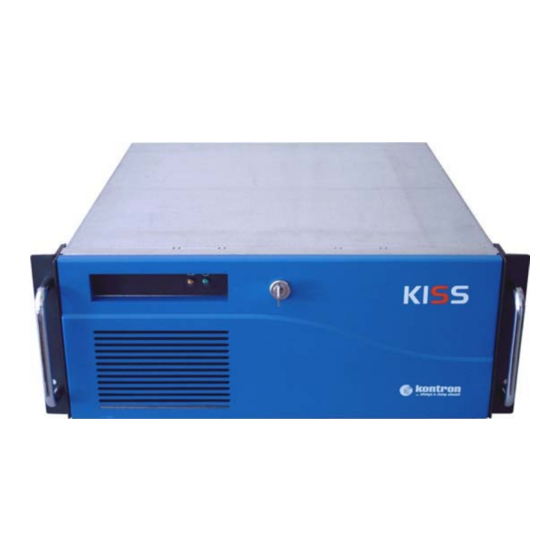
Page 19: Figure 1: Kiss Platform
Before putting the system into operation for the first time (before mounting/installation into an industrial cabinet), you have to open the unit as described in "Accessing Internal Components” (page39) and remove the drive locking screws (fig. 2, 3, 4, 5: pos.14). KISS4U User’s Guide page 19... -
Page 20: Figure 2: Kiss-Platform, Opened Rackmount Version With Motherboard
16. External interfaces of the 8. Fan slide-in module with captive motherboard knurled screw 17. Grounding stud 9. 19” rack mountable bracket with 18. Expansion card slots handle (not available for tower and desktop version) page 20 KISS4U User’s Guide... -
Page 21: Figure 3: Kiss-Platform, Opened Rackmount Version With Motherboard
Before putting the system into operation for the first time (before mounting/installation into an industrial cabinet), you have to open the unit as described in the "Accessing Internal Components" section and remove the drive locking screws (fig. 2, 3, 4, 5: pos.14). KISS4U User’s Guide page 21... -
Page 22: Figure 4: Kiss-Platform, Opened Desktop Version With Sbc-Board (Kr-4201-Pci951)
5. Single Board Computer 15. External interfaces of the SBC- (example) board 6. Card holder 16. Additional external interfaces 7. Card guides 17. Grounding stud 8. Fan slide-in module with captive 18. Expansion card slots knurled screw page 22 KISS4U User’s Guide... -
Page 23: Figure 5: Kiss-Platform, Opened Desktop Version With Sbc-Board (Kr-4201-Pci951)
Before putting the system into operation for the first time (before mounting/installation into an industrial cabinet), you have to open the unit as described in "Accessing Internal Components" (page 39) and remove the drive locking screws (fig. 2, 3, 4, 5: pos.14). KISS4U User’s Guide page 23... -
Page 24: Front Side
The KISS tower version is delivered without a 19” rack mountable bracket. The operating elements (ATX-power button and reset button), the USB interfaces and the integrated drives are located at the front side of the KISS-Platform, behind the front access door. page 24 KISS4U User’s Guide... -
Page 25: Figure 8: Front Side (Rackmount Version) With Opened Front Access Door
7. 1x internal 3.5“- or 1x external 4. Slot for the locking mechanism Slimdrive bay (not available in 5. 2x 3.5” drive bay (shown with one tower version) FDD installed) 8. Reset-button 9. ATX-power button 10. 2x USB interface KISS4U User’s Guide page 25... -
Page 26: Operating Elements
On/Off power switch of the power supply unit is switched “Off” (for KISS systems with a power supply unit (PSU) which has a PSU On/Off power switch) Because of this, the power cord and its connectors must always remain easily accessible. page 26 KISS4U User’s Guide... -
Page 27: Interfaces On The Front Side
Important: The KISS-Platform comes equipped with two keys. If the keys get lost or damaged, then the front access door can be opened only by Kontron Embedded Computers service personnel. KISS4U User’s Guide... -
Page 28: Rear Panel
SBC-board, any additional interfaces (in system configurations with an SBC-board), the power supply unit and the air exhaust openings. Note: The number of KISS-Platform interfaces will vary depending on the configuration. page 28 KISS4U User’s Guide... -
Page 29: Figure 9: Kiss4U With Motherboard (Example) - Rear Side (Always With 300 W Psu)
Figure 9: KISS4U with Motherboard (example) – rear side (always with 300 W PSU) Legend for figures: 9 and 10: 1. PSU Fan 10. Interfaces of the SBC-board or of 2. PSU On/Off switch (depending the motherboards (depending on on the integrated PSU) the system configuration) 3. -
Page 30: Interfaces On The Rear Side
USB Interfaces KISS is equipped with two USB interfaces at the front side. These connectors allow you to connect different USB-compatible devices to the KISS-Platform. page 30 KISS4U User’s Guide... - Page 31 The KISS-Platform should only be operated with a functioning fan slide-in module (refer to the “Replacing the System’s Fans” section). Defective components should only be replaced with Kontron original spare parts. the part number of the fan slide-in module: 0-0084-3604 The temperature conditions of the system (dependent on the ambient temperature and the system load) are acquired by two temperature sensors.
-
Page 32: Side View
Platform for system installation into a 19” industrial cabinet. Refer to the “Slide Rails (Option)” chapter. Figure 11: Tapped M4 metric holes to attach a telescope rail 1. Side view of the KISS-Platform 2. 4x tapped M4 metric holes (on both sides) page 32 KISS4U User’s Guide... -
Page 33: Integrated Motherboard / Sbc-Board
To expand your system with additional cards, please observe the power con- sumption specifications in the “Main Specifications” chapter and ensure that each additional card does not consume more than 25 W of power. KISS4U User’s Guide page 33... -
Page 34: Backplanes (For Configurations With Sbc-Boards)
1. 2x 32 bit PICMG 1.0 CPU-slot 2. 11x 32 bit PCI-slot 3. 1x 16 bit ISA-slot 4. 1x 16 bit ISA- / 32 bit PCI shared slot (if the left PICMG CPU-slot is not fitted with a SBC- card) page 34 KISS4U User’s Guide... -
Page 35: Specifications
Expansion slots (at the rear side) Up to maximum of 12 free expansion slots (The number and type of the free expansion slots depend on the integrated board, the type of the board and the system‘s hardware configuration.) KISS4U User’s Guide page 35... -
Page 36: Electrical Specifications
30 G, 11 ms duration, half sine Storage/transit shock Operating vibration 10 – 500 Hz, 1.0 G Storage / transit vibration 10 – 500 Hz, 2.0 G Acoustic noise <35 dB at 1 m in front of the system, full load page 36 KISS4U User’s Guide... -
Page 37: Chapter 2: Installation
Chapter 2: Installation Overview This chapter contains installation instructions for the KISS4U. Only qualified, experienced, authorized electronics service personnel should access the interior of a computer. Any attempt to remove the cover and expose the computer’s components must be exercised with extreme caution. -
Page 38: Attaching The Rubber Feet
“Accessing Internal Components” section and remove the drive locking screws (rackmount and desktop versions only). Drive Cage Drive Locking Screws Figure 14: KISS-Drive cage with drive locking screws page 38 KISS4U User’s Guide... -
Page 39: Accessing Internal Components
2. Loosen the captive knurled screws on the rear side of the unit that secure the cover. Figure 15: Loosen the captive knurled screws 3. Lift the cover away. Figure 16: Removing the device cover KISS4U User’s Guide page 39... -
Page 40: Figure 17: Kiss-Platform Without Cover
Figure 18: Removing the fastening screw the card hold-down bracket Legend for figures 18, 19 and 20: 1. Bolts for the card hold-down bracket 2. Threaded bolt 3. Locating holes 4. PCB holder 5. Hole for the fastening screw page 40 KISS4U User’s Guide... -
Page 41: Figure 19: Bolts And Fastening Point For The Card Hold-Down Bracket
(especially for full-length card) into the slot of the PCB holder (height adjustable). Thus the card is firmly kept in place during high mechanical load (shock and vibrations). 8. Close the KISS-Platform and secure the cover with the captive knurled screws. KISS4U User’s Guide page 41... -
Page 42: Instructions For Installation In A 19" Cabinet
The voltage feeds must not be overloaded. Adjust the cabling and the external overcharge protection to correspond with the electrical data indicated on the type label located on right side of the unit. page 42 KISS4U User’s Guide... -
Page 43: Starting Up
1. Connect the supplied AC power cord into the system AC power plug (see fig. 21 and 22). 2. Connect the other end of the AC power cord into a corresponding outlet. KISS4U User’s Guide page 43... - Page 44 Use the power cord suitable for the power supply in your country. Do not remove or alter the grounding prong on the power cord. In situations where a two-slot receptacle is present, have it replaced with a properly grounded three-prong grounding type receptacle. page 44 KISS4U User’s Guide...
-
Page 45: Standard Interfaces - Pin Assignments
RTS (Request to Send) CTS (Clear to Send) RI (Ring Indicator) Parallel Port Signal name 25-pin SUB D-socket -STROBE DATA0 DATA1 DATA2 DATA3 DATA4 DATA5 DATA6 DATA7 -ACKN BUSY SELECT -AUTOFD -ERROR -INIT -SLCTIN 18–25 KISS4U User’s Guide page 45... -
Page 46: Operating System And Hardware Component Drivers
If you have ordered your system without a pre-installed operating system, you have to install the operating system and the corresponding drivers for the ordered configuration (optional hardware components). Consider the manufacturer’s specifications for the operating system and the integrated hardware components. page 46 KISS4U User’s Guide... -
Page 47: Chapter 3: Maintenance And Prevention
Chapter 3: Maintenance and Prevention Kontron Embedded Computers systems require minimal maintenance and care to keep them operating correctly. Occasionally wipe the system with a soft dry cloth. You should only remove persistent dirt by use of a soft, slightly damp cloth (use only a mild detergent). -
Page 48: Figure 23: Kiss-Platform With Fan Slide-In Module
Figure 23: KISS-Platform with fan slide-in module nach oben heraus. Figure 24: Side view of the fan slide-in module Figure 25: Bottom view of the fan slide-in module page 48 KISS4U User’s Guide... -
Page 49: Figure 26: Fan Case Of The Kiss-Platform Without Fan Slide-In Module
(fig. 26, pos. 8) to the centering slot (fig. 25, pos. 6). 4. Secure the fan slide-in module with the captive knurled screw. 5. Close the KISS-Platform and secure the cover with the captive knurled screws. KISS4U User’s Guide page 49... -
Page 50: Cleaning The Filter Mat
Replace the filter mat holder to the front side of the chassis (see fig. 28, pos. 3 and fig. 29, pos. 4). 7. Tighten the screw to secure the filter mat holder to the chassis. page 50 KISS4U User’s Guide... -
Page 51: Figure 28: Location For Filter Mat Holder
CAUTION When inserting the filter mat, ensure that the denser side of the mat is facing the fans. Defective components should only be replaced with Kontron original spare parts. the part number of the filter mat: 0-0084-2953 Figure 28: Location for filter mat holder... -
Page 52: Replacing The Lithium Battery
5. Make sure that you insert the battery the right way around. The plus pole must be on the top! 6. The lithium battery must be replaced with an identical battery or a battery type recommended by Kontron Embedded Computers. 7. Reinstall the expansion cards which you removed and reconnect their data cables. -
Page 53: Appendix A: Slide Rails (Optional)
Appendix A: Slide Rails (Optional) Kontron offers slide rails for installing the KISS-Platform into a 19“ industrial cabinet. These can be ordered under: “Slide rails” - Set No.: 3-A260-0244. Figure 30: Attaching the inner side of the slide rail Figure 31: Kiss-Plattform with slide rail Legend for figures: 30 and 31: 1. -
Page 54: Slide Rails Accessories And Assembling
One pair of short front brackets (with screws and washers) One pair of long rear brackets (with screws and washers) 2 x bar nut kits 8 x M4x 6 nuts For assembling refer to fig. 32. Figure 32: Assembling of the “Slide-rails” set page 54 KISS4U User’s Guide... -
Page 55: Mounting Into An Industrial Cabinet (With Slide Rails)
• Loosen the screws on the rear mount brackets and adjust the brackets. • Loosen the screws on the chassis side. • Cycle the unit a few times. • If movement has improved tighten the screws and cycle again. KISS4U User’s Guide page 55... - Page 56 This page intentionally left blank. page 56 KISS4U User’s Guide...
-
Page 57: Appendix B: Troubleshooting
Avoid shorting the circuits as this can damage the computer. CAUTION The following procedures involve working with a device that is sensitive to static electricity. Use proper precautions to protect against electrostatic discharge (ESD). Only qualified personnel should attempt these procedures. KISS4U User’s Guide page 57... -
Page 58: Troubleshooting Procedures
Occasionally, Flash BIOS can be corrupted by hardware or software. Check the Kontron Web site for the latest version of BIOS and follow the steps for reflashing. When upgrading or adding hardware to an existing system, note board positions and cables. -
Page 59: Common Problems
When the short is removed, the power supply should automatically sense the removal of the short and restore operation. If cables become damaged, contact Kontron for repair or replacement System is not Memory is not seated... - Page 60 This page intentionally left blank. page 60 KISS4U User’s Guide...