
Related Manuals for Kontron PxV414


Summary of Contents for Kontron PxV414
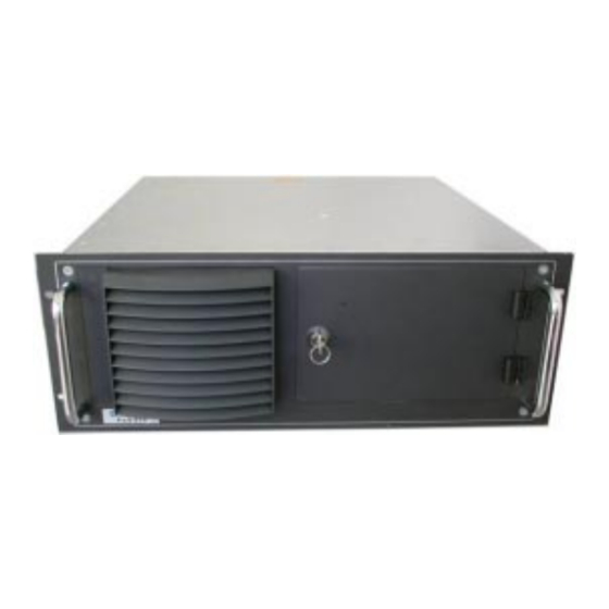
- Page 1 PxV414 – 4U Platform User’s Manual Version 1.11 Kontron Embedded Computers GmbH 0-0096-2629...
-
Page 2: Table Of Contents
Ports on the Rear Panel ..................19 Power Supply Unit...................19 To Padlock the Device..................19 Versions of the Power Supply Unit ..............20 Power Cord Connection..................21 Internal Drive Bays....................22 Backplane ......................23 SBC Board ......................24 Assembly, Disassembly ..................25 Accessing Internal Components ................25 PxV414 – 4U Platform User Manual... - Page 3 Parallel Port......................40 PS/2 Keyboard - Connector ................41 PS/2 Mouse - Connector ..................41 PS/2 Keyboard and Mouse - Connector.............. 42 VGA-Interface - Connector .................. 42 Technical Support ..................... 43 Returning Defective Merchandise ............... 44 PxV414 – 4U Platform User Manual...
-
Page 4: Introduction
Kontron Embedded Computers is aware of such errors or inaccuracies or that Kontron Embedded Computers is unaware of these as a result of gross negligence and Kontron Embedded Computers has failed to eliminate these errors or inaccuracies for this reason. -
Page 5: Symbols Used In This Manual
This symbol indicates that the product or parts thereof may be damaged if the corresponding warning notices are not observed. This symbol indicates general information about the product and the user manual. This symbol precedes helpful hints and tips for daily use. PxV414 – 4U Platform User Manual... -
Page 6: Important Instructions
Important Instructions This chapter contains instructions which must be observed when using your PxV414 – 4U Platform. The manufacturer’s instructions provide useful information on your PxV414 – 4U Platform. Note on the Guarantee Due to their limited service life, parts which by their nature are subject to a particularly high degree of wear (wearing parts) are excluded from the guarantee beyond that provided by law. -
Page 7: Safety Instructions
Observe the warnings and instructions on the device and in the manual. The PxV414 is built and tested by Kontron Embedded Computers in accordance with EN60950/VDE0805 and left the works in a perfectly safe condition. In order to maintain this condition and ensure safe operation, the user must observe the instructions and warnings contained in this manual. - Page 8 SELV circuit (security low voltage output) in accordance with EN60950. q In devices with -48 V DC PSU (PxV414-C) it is not allowed to remove or to bridgeover the installed ATX-connector with the Kontron-ATX cable extension (T10 A fuse integrated in the 3.3 V circuit).
-
Page 9: Operation Of Laser Source Devices
2. Keep electrostatic sensitive parts in their containers until they arrive at static- free stations. 3. Always be properly grounded when touching a sensitive board, component, or assembly. 4. Store electrostatic-sensitive boards in protective packaging or on conductive foam. PxV414 – 4U Platform User Manual... -
Page 10: Grounding Methods
Lithium Battery ”. Warning Danger of explosion when replacing with wrong type of battery. Replace only with the same or equivalent type recommended by the manufacturer. Dispose of used batteries according to the manufacturers instructions. PxV414 – 4U Platform User Manual... -
Page 11: Fcc Statement
(EMC Rules 89/336/EWG) and/or the German EMC laws apply. If the user modifies and/or adds to the equipment (e.g. installation of add-on cards), the prerequisites for the CE conformity declaration (safety requirements) may no longer apply. PxV414 – 4U Platform User Manual... -
Page 12: Scope Of Delivery
DVI-Output adapter with bracket and cable (optional) 1x CD-ROM with the drivers and the SBC-User’s Manual) Type Label and Product Identification The type label of the PxV414 – 4U Platform is placed on the right side of the unit. Product designation on Product identification... -
Page 13: Product Description
Product Description Product Description The PxV414 is a feature-packed 4U (19") system, designed for high-performance applications. The PxV414 – 4U Platform is designed as a rackmount device. It includes backplane with 32-bit PCI design slots. ® ® ® ® Your system can accommodate a Pentium III... - Page 14 Product Description Fig 3: PxV414 – 4U Platform opened ® 6 SBC card interfaces 1 E-PAC 7 SBC board 2 5,25” bay (in the pictured configuration is built in a CD-ROM 8 Backplane drive) 9 Cards holder 3 Power Supply Unit (PSU)
-
Page 15: Front Panel
4 Drives door with lock The operating elements (power switch and reset button) and the integrated drives are located at the front side of the PxV414 – 4U Platform, behind the drive door. Fig. 5: Front panel with opened doors 1 LED indicators 4 3,5”... -
Page 16: Operating Elements
Fig. 6: LED panel Press this button to turn the system on or off. Power Switch If your system no longer reacts, you must restart the PxV414 Reset Taster –4U Platform. To do this, press the restart button. Keylock Switch You can use the keylock switch to block the keyboard. If this keyboard lock is activated it is not possible to make any entries via the keyboard. -
Page 17: Led Indicators
Product Description LED Indicators On the left side next to the handle of the PxV414 – 4U Platform there are the indicator LEDs. This LED lights up green when the power supply is correct Power LED and the system is turned on. If this LED does not light up... -
Page 18: Frontal Accessible Drive Bays
Product Description Frontal Accessible Drive Bays The PxV414 – 4U Platform is equipped with three front accessible drive bays: one 3,5” bay two5,25” bays. Ports on the Front Panel Keyboard Connection You can connect a PS/2 compatible keyboard to the Mini –DIN socket. -
Page 19: Rear Panel
Rear Panel On the rear panel are located the external interfaces of the integrated SBC board and the power supply unit. The configuration respectively the number of the PxV414 – 4U Platform interfaces may vary depending on the device equipment. -
Page 20: Ports On The Rear Panel
For detailed SBC board interface description refer to the supplied SBC board manual. Power Supply Unit Each PxV414 – 4U Platform can be equipped optionally depending on the power supply unit (PSU) with an AC-PSU or a DC-PSU. To Padlock the Device There are two brackets (one on the cover the other on the chassis) on the device backside. -
Page 21: Versions Of The Power Supply Unit
Product Description Versions of the Power Supply Unit The power supply unit is placed on the rear side of PxV414 – 4U Platform. Each PxV414 – 4U Platform can be equipped optionally depending on the power supply unit (PSU) with an AC-PSU or a DC-PSU. -
Page 22: Power Cord Connection
Make sure that you have the right polarity of the connection. 2. Installing the Philips screws to secure the DC power cord into the DC terminal. PxV414 – 4U Platform User Manual... -
Page 23: Internal Drive Bays
Product Description Internal Drive Bays Internal there are two drive bays: q One 3.5“ bay (for IDE/SCSI hard disk q One 1.8“ bay (for IDE flash disk) PxV414 – 4U Platform User Manual... -
Page 24: Backplane
Product Description Backplane On your PxV414 – 4U system is integrated one 32-bit backplane. The backplane is provided for the standard version with: q two PICMG SBC locations (only one SBC installed at any given time) q seven PCI expansion slots to expand your system (four of them full size and three of them half size). -
Page 25: Sbc Board
® Your system can accommodate a Pentium III /Celeron - or a Pentium 4/Celeron CPU compatible Single Board Computer (SBC). For detailed information refer to the delivered technical reference manual of the SBC board. PxV414 – 4U Platform User Manual... -
Page 26: Assembly, Disassembly
Failure to take heed of this warning instruction can result in damage to the device. Please consult the documentation provided by the additional card manufacturer for instructions before attempting to install/remove an additional card into/from the PxV414 – 4U Platform. PxV414 – 4U Platform User Manual... - Page 27 2. Remove the captive knurled screws located at the rear of the unit securing the cover. Fig. 11: Removing cover 3. Lift the back the cover or pull it out. Fig. 12: Removing cover PxV414 – 4U Platform User Manual...
- Page 28 Retain the screws for later use. Fig. 13 Removing the card holder Fig. 14 PxV414 – 4U Platform without card holder 5. For the installing/removing the additional card please remove the corresponding additional card/slot cover from the backplane slot. Fasten the additional card/slot cover to the device rear chassis.
- Page 29 6. Reinstall the card holder and secure it using the four retaining screws (two screws on each side) (see Fig. 13). 7. Please close the PxV414 – 4U Platform and secure the cover with the captive knurled screws. PxV414 – 4U Platform User Manual...
-
Page 30: Replace The Lithium Battery
7. Reinstall the removed additional cards and reconnect the removed data cable. 8. Close the Unit as described in chapter “Installing the Additional Cards” (step 6-7) Battery ejector spring Lithium battery Battery socket SBC card Fig. 15: Lithium battery placement PxV414 – 4U Platform User Manual... -
Page 31: Installation Instructions
Refer to chapter “Ports on the Rear Panel ” for the description of the interfaces. Important Instructions! The PxV414 has to be installed and operated only by trained and qualified personal. Since the device may weigh up to 20 kg, it is advisable to have a colleague assist in the installation. - Page 32 The type label is located on the right side of the device. For DC power supplies please observe that the supply circuit must withstand loads minimum 50A for the 24V power supply and 25A for the -48V power supply. PxV414 – 4U Platform User Manual...
-
Page 33: Maintenance And Prevention
Kontron Embedded Computers systems require minimal maintenance and care to keep them operating correctly. q Clean the PxV414 – 4U Platform with light soiling with a dry cloth. q You should only remove stuff-necked dirt with a mild detergent and a soft cloth. - Page 34 Do not clean the filter mat with a piercing jet of water or wring it out. 3. After cleaning and drying the filter mat simply place it back to the front panel in front of the cooling fan. Replace the air filter hood. PxV414 – 4U Platform User Manual...
-
Page 35: Main Specifications
1x Reset button 1x Keylock (optional) LED indicators On the front panel: 1x Power LED 1x HDD activity LED 1x Temperature control LED (optional) AC power plug / DC On the rear panel power screw terminals PxV414 – 4U Platform User Manual... - Page 36 Power on +3,3 VDC 15 W Power on +5 VSB Please take care, that the total PSU output power of your system doesn’t exceed the following value: PxV414-A 250 W PxV414-C 220 W PxV414-F PxV414 – 4U Platform User Manual...
-
Page 37: Electrical Specifications
4U (177 mm) Width Front: 19”; Chassis: 17.56" (446 mm) Depth Front: 1.79" (45.5 mm) Chassis: 18.77” (464 mm) Weight 20 kg approximately (without packaging) Housing steel with zinc plating, Steel front panel black PxV414 – 4U Platform User Manual... -
Page 38: Environmental Specifications
58 – 500 Hz, 2.0 G Storage / transit vibration 10 – 58 Hz, – 0.30 mm 58 – 500 Hz, 4.0 G Acoustic noise <50 dB at 1 m in front of the system at full load PxV414 – 4U Platform User Manual... -
Page 39: Ce-Directives, Standards And Approvals
Standards EN 50081-1/ -2 (emission) EN 50082-1/ -2 (immunity) EUROPE EN 55022/ B: 1994 (CISPR22) U.S.A. FCC 47 CFR Part 15, Class A Approvals Standards EN 60950, 3 edition TÜV IEC 60950, 3 edition PxV414 – 4U Platform User Manual... -
Page 40: Standard Interfaces - Pin Assignments
COM1 (RS232) Pin Signal name 9-pin SUB D-plug DCD (Data Carrier Detect) RXD (Receive Data) (Transmit Data) (Data Terminal Ready) GND (Signal Ground DSR (Data Set Ready) (Request to Send) (Clear to Send) (Ring Indicator) PxV414 – 4U Platform User Manual... -
Page 41: Parallel Port
Standard Interfaces – Pin Assignments Parallel Port Signal name 25-pin SUB D-socket -STROBE DATA0 DATA1 DATA2 DATA3 DATA4 DATA5 DATA6 DATA7 -ACKN BUSY SELECT -AUTOFD -ERROR -INIT -SLCTIN 18–25 PxV414 – 4U Platform User Manual... -
Page 42: Ps/2 Keyboard - Connector
6 pin Mini-DIN socket Keyboard data not connected +5 V Keyboard clock not connected PS/2 Mouse - Connector Signal name 6 pin Mini-DIN socket Mouse data not connected +5 V Mouse clock not connected PxV414 – 4U Platform User Manual... -
Page 43: Ps/2 Keyboard And Mouse - Connector
6 pin Mini-DIN socket Keyboard data Mouse data +5 V Keyboard clock Mouse clock VGA-Interface - Connector Signal name 15-pin SUB-D socket (female) green blue 5, 6, 7,8 GND DDC Data HSYNC VSYNC DDC Clock PxV414 – 4U Platform User Manual... -
Page 44: Technical Support
Be ready to explain the nature of your problem to the service technician. If you have any questions about Kontron Embedded Computers or our products and services, you may reach us at the aforementioned numbers, or at : www.kontron.com... -
Page 45: Returning Defective Merchandise
(+49) 8165-77 311 E-mail: service@kontron.com 2. Make sure that you receive an RMA number from Kontron Embedded Computers-Service before returning any merchandise. Clearly write or mark this number on the outside of the package you are returning. 3. Describe the device failure behavior.
Need help?
Do you have a question about the PxV414 and is the answer not in the manual?
Questions and answers