
Subscribe to Our Youtube Channel
Related Manuals for PROEL DSO26


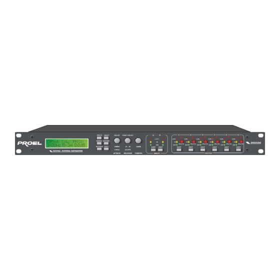
Summary of Contents for PROEL DSO26
- Page 1 SOUND REINFORCEMENT DSO26 DIGITAL SYSTEM OPTIMIZER U S E R ’ S M A N U A L www.proelgroup.com MADE IN EUROPE...
-
Page 2: Dso26 Quick Reference
DSO26 User Manual DSO26 Quick Reference Accessing channels: press channel’s GAIN button. First press accesses that channel’s gain. To scroll through a channels parameters, use the BACK and NEXT keys. Second press accesses last viewed parameter. Third press will drop back to the default screen. -
Page 3: Table Of Contents
DSO26 User Manual CONTENTS DSO26 QUICK REFERENCE .....................2 The Menus and their Contents .......................... 2 Notes.................................. 2 CONTENTS .........................3 IMPORTANT SAFETY INFORMATION ................6 THANKS..........................7 UNPACKING THE DSO26 ....................7 INTRODUCTION .........................8 Features................................8 FRONT PANEL FAMILIARISATION...................9 REAR PANEL CONNECTIONS ..................10 OPERATING THE DSO26....................11 Preliminary Set-up ............................ - Page 4 DSO26 User Manual MENU SELECTION......................24 INPUT SETUP SUB-MENU....................25 Gang Inputs ..............................25 X-OVER SUB-MENU......................26 Load a Xover ..............................26 Design a Xover ..............................26 Store a Xover ..............................26 Erase a Xover Mem ............................26 SECURITY SUB-MENU ....................27 User Specific..............................27 Xover Only ...............................
- Page 5 DSO26 User Manual Crossover Filter Slopes ........................... 32 Time Alignment..............................33 Output Limiters ..............................34 Setting Accurate Limiter Thresholds........................ 35 FACTORY PRESETS......................37 EDGE presets ..............................37 TFL presets..............................39 Voltage gain of TFL amplifiers ......................... 42 SPECIFICATIONS......................43 WARRANTY........................44 OPTIONS AND ACCESSORIES..................44 APPENDICES ........................45...
-
Page 6: Important Safety Information
DSO26 User Manual An example of this equipment has been tested and found to comply with the following European and international Standards for Electromagnetic Compatibility and Electrical Safety: Radiated Emissions (EU): EN55013-1 (1996) RF Immunity (EU): EN55103-2 (1996) RF Immunity, ESD, Burst Transient, Surge, Dips &... -
Page 7: Thanks
DSO26 User Manual THANKS Thank you for choosing the DSO26 for your application. Please spend a little time reading through this manual, so that you obtain the best possible performance from the unit. All our products are carefully designed and engineered for cutting-edge performance and world-class reliability. -
Page 8: Introduction
1U unit. To achieve this, the DSO26 has two inputs and six outputs which can be configured in five basic crossover modes – 3 x 2 way; 2 x 3 way; 4 way; 5 way; and 6 way. -
Page 9: Front Panel Familiarisation
DSO26 User Manual FRONT PANEL FAMILIARISATION LCD Screen: shows menu options, channel information, and various parameters as they are adjusted. Next Key : moves forwards through the list of available parameters. Back Key : moves back through the list of available parameters. -
Page 10: Rear Panel Connections
DSO26 User Manual REAR PANEL CONNECTIONS Power Switch: turns the units mains supply off and on. Mains Fuse: located in a finger-proof holder adjacent to the mains inlet. A spare fuse is also located in this holder. Mains Inlet: connected via a standard IEC socket. -
Page 11: Operating The Dso26
DSO26 User Manual OPERATING THE DSO26 If you want to use the Proel EDGE and TFL presets you can skip this section and jump directly to ‘Load a Xover’ page 26. Preliminary Set-up The procedure below should be followed when first installing a DSO26. -
Page 12: Dso26 Configurations
DSO26 CONFIGURATIONS Introduction To simplify the set-up of the DSO26, 5 crossover modes are selectable from the X-over sub-menu. These all have parametric equalisers, high and low pass filters, gain controls, delay and limiters. The following set of diagrams detail how each of the five modes is internally configured. -
Page 13: X 3 Way
DSO26 User Manual 2 x 3 way This format feeds input A to outputs 1, 2, and 3 designated low, mid, and high respectively. Input B feeds outputs 4, 5, and 6, as low, mid, and high respectively. Note that this configuration, as with the 2 x 2 way, can have the outputs ganged for stereo operation. -
Page 14: Way + 2
DSO26 User Manual 4 way + 2 This format feeds input A to outputs 1, 2, 3, and 4 designated low, lo-mid, hi-mid and high respectively. Outputs 5 and 6 are configured as auxiliaries, with their source being either input B, or the sum or inputs A and B. -
Page 15: Way + 1
DSO26 User Manual 5 way + 1 This format feeds input A to outputs 1, 2, 3, 4, and 5 designated sub, low, lo-mid, hi-mid and high respectively. Output 6 is configured as an auxiliary, with the source being either input B, or the sum or inputs A and B. -
Page 16: Way
DSO26 User Manual 6 way This format feeds input A to all outputs designated lo-sub, through high, 1 to 6 respectively. AES/EBU Digital input and output interfaces are available as an option (factory fitted only). Input and output balancing transformers are also available as an option (factory fitted only). -
Page 17: Screen Layouts Overview
DSO26 User Manual SCREEN LAYOUTS OVERVIEW Xover Sub-Menu Input Setup Sub-Menu Security Sub-Menu NEXT ENTER MENU-NEXT- -ENTER System Sub-Menu MENU-ENTER Default Screen ENTER Crossover Name MENU-NEXTx3- -ENTER NEXT INPUT OUTPUT MENU-NEXTx4- GAIN GAIN -ENTER Input Section Screens Output Section Screens... -
Page 18: Audio Function Screens
DSO26 User Manual AUDIO FUNCTION SCREENS Gain Screen To adjust the gain: Use the ‘GAIN’ control. Each input and output has an individual gain screen. The inputs have a range of +6dB to –40dB, adjustable in 0.1dB steps and the outputs have a range of +15dB to –40dB, again adjustable in 0.1dB steps. -
Page 19: Polarity Screen
DSO26 User Manual Polarity Screen To adjust the polarity: Use the ‘GAIN’ control to switch between + and -. Each output has an independent polarity screen. This gives the flexibility to reverse (flip by 180°) the phase of individual outputs. -
Page 20: Delay Screen
DSO26 User Manual Delay Screen To adjust delay settings: Use the ‘DELAY’ control for coarse control. (1mS steps) Use the ‘FINE DELAY’ control for fine control. (2.6µS steps) Each input and output has an independent delay time control. Input delay (base delay) is adjustable in 1mS steps. -
Page 21: High And Low Pass Filter Screens
DSO26 User Manual High and Low Pass Filter Screens To adjust HPF/LPF settings: Use the ‘FREQ’ control for the frequency. Use the ‘SLOPE’ control for the slope. Each output has an independent high pass filter and an independent low pass filter. Both filters have a range of selectable slopes, which are Bessel 12dB, 18dB and 24dB, Butterworth 12dB, 18dB and 24dB, and Linkwitz-Riley 24dB. -
Page 22: Parametric Equaliser Screen
DSO26's exceptional noise performance and greatly improved low frequency stability. (Note: To show parametric filters in bandwidth (BW) rather than ‘Q’, go into the ‘System sub-menu’, select ’filter Q or BW’, select BW.) -
Page 23: Limiter Screen
DSO26 User Manual Limiter Screen To adjust limiter settings: Use the ‘ATTACK’ control to adjust the attack time. Use the ’RELEASE’ control for the release time. Use the ‘THRESH’ control for the limiter threshold. Each output has an independent high performance limiter. -
Page 24: Menu Selection
DSO26 User Manual MENU SELECTION The following menu selections are available: Xover Sub-menu: Load a Xover – loads a pre-defined crossover. Design a Xover – starts the set-up wizard for designing a new crossover. Store a Xover – stores all output settings as a defined crossover. -
Page 25: Input Setup Sub-Menu
DSO26 User Manual INPUT SETUP SUB-MENU There is one option in this menu: Gang Inputs Gangs A and B inputs so that precise adjustments can be made to both inputs simultaneously. Both GAIN LEDs will light when the inputs are accessed and the LCD will show A+B. -
Page 26: X-Over Sub-Menu
DSO26 User Manual X-OVER SUB-MENU Load a Xover Loads a stored crossover from the selection available. Enter accepts the selected name and loads immediately. Design a Xover Opens a wizard to design a crossover. Options include format type, ganging of outputs, routing and automatic limiter time constants. -
Page 27: Security Sub-Menu
DSO26 User Manual SECURITY SUB-MENU After selecting the ‘Security Sub-Menu’ and pressing ENTER, select one of the lock types, after choosing the most appropriate one for your application. As ever, ENTER will confirm your selection. User Specific Upon pressing ENTER to select this type of lock, each parameter group is presented in turn. -
Page 28: Entering The Password To Complete The Locking Operation
DSO26 User Manual Entering the Password to Complete the Locking Operation After selection of the lock type from the list above, a four-digit security code will be asked for. This can be entered by using the ‘FREQ’ control to select a character, and the ‘BACK’... -
Page 29: System Sub-Menu
DSO26 User Manual SYSTEM SUB-MENU System Status Displays unit information including software version and temperature. Curr. Temp. = current temperature in degrees Celsius. Max1. Temp. = maximum temperature this session. Max2. Temp. = maximum temperature ever reached. LCD Contrast Adjusts the LCD contrast from 0 to 100. -
Page 30: Interface Sub-Menu
DSO26 User Manual INTERFACE SUB-MENU Interface Setup If the interface is enabled, the option will become available to select the baud rate. This must be set to match tat on the PC to be used for the program update. Typically, the set-... -
Page 31: Aes / Ebu Sub-Menu
DSO26 User Manual AES / EBU SUB-MENU Connection of AES/EBU signals is via the existing rear panel XLR connectors. With the AES/EBU option fitted, AES Receive and Diagnostic modes are provided. Routing Options Selects the input source – either analogue or digital, and similarly the output source, again either analogue or digital. -
Page 32: Operating Notes
It should also be noted that the turnover frequency displayed on the DSO26 is the -3dB point for all slopes except 24dB Linkwitz-Riley where the -6dB point is shown. If the -6dB point is to be used for the... -
Page 33: Time Alignment
DSO26 User Manual Time Alignment A further advantage of the DSO26 over conventional products is the provision of an independently adjustable delay section for each output. This allows the true arrival time from multiple drivers to precisely aligned rather than relying on the compromise 'phase adjust' approach. -
Page 34: Output Limiters
DSO26 User Manual Output Limiters High performance digital limiters are provided for each output with control over attack time, release time and threshold level parameters - see page 23 for details. This level of control allows the user to balance the required subjective quality of the limiter against the driver protection requirements. -
Page 35: Setting Accurate Limiter Thresholds
DSO26 User Manual Setting Accurate Limiter Thresholds The limiters built into the DSO26 are intended to be used for for loudspeaker driver protection, as opposed to amplifier protection. All modern professional power amplifiers designed for live sound use have their own limiters which are tailored to protecting the amplifier from clipping. - Page 36 DSO26 User Manual Subtract this gain figure from the dB value obtained from the table to find the required absolute setting for the limiter thresholds. Note that, for safety, always set the limiter threshold 1 or 2 dB below the maximum allowable worked out using the above method.
-
Page 37: Factory Presets
DSO26 User Manual FACTORY PRESETS DSO26 is factory preloaded with presets for the EDGE and TFL loudspeaker lines. The presets were optimized by engineers at Proel to achieve the best performance. As a general rule Sat and Aux outputs are not locked and can be programmed by users to fulfill their needs. - Page 38 DSO26 User Manual EDGE121+218+212A 4 way crossover plus 2 aux’s Out 1 Out 4 Out 2 Mid Low Out 5 B2Sub Out 3 Mid High Out 6 Allowed Sub, B2Sub gain trim and delay time; normal High shelving eq. ANALOGUE...
-
Page 39: Tfl Presets
TFL presets are intended to optimse the performance of the TFL loudspeaker line. Due the non constant voltage gain of the Proel PRL line of amplifiers (see table at the end of this section), these presets are valid ONLY if used with the PRL amplifiers specified. - Page 40 DSO26 User Manual TFL115SP + SAT 2x3 way crossover Out 1 Out 4 Out 2 Out 5 Out 3 Out 6 Sub PRL1400 TFL115SP + 10P BA 2x3 way crossover Out 1 Out 4 Out 2 Out 5 Out 3...
- Page 41 DSO26 User Manual TFL215SP + SAT 2x3 way crossover Out 1 Out 4 Out 2 Out 5 Out 3 Out 6 Sub PRL950 bridged TFL215SP + 12P BA 2x3 way crossover Out 1 Out 4 Out 2 Out 5 Out 3...
-
Page 42: Voltage Gain Of Tfl Amplifiers
DSO26 User Manual Voltage gain of TFL amplifiers Amplifier Voltage gain [dB] PRL250 PRL600 PRL950 PRL1400 PRL600 bridged PRL950 bridged PRL1400 bridged... -
Page 43: Specifications
DSO26 User Manual SPECIFICATIONS Inputs: 2 electronically balanced High and Lowpass Filters Impedance: > 10k ohms. Filters: 1 of each per output. CMRR : >65dB 50Hz - 10kHz. Freq. Range HPF: 10Hz - 16kHz 1/36 octave steps. Outputs: 6 electronically balanced Freq. -
Page 44: Warranty
Defects caused by unauthorised modifications, misuse, negligence, act of God or accident, or any use of this product that is not in accordance with the instructions provided by Proel, are not covered by this warranty. This warranty is exclusive and no other warranty is expressed or implied. Proel is not liable for consequential damages. -
Page 45: Appendices
DSO26 User Manual APPENDICES Appendix 1: Limiter threshold in dB to Vrms lookup table. Vrms Vrms 9.75 1.38 8.69 1.23 7.75 1.09 6.90 0.98 6.15 0.87 5.48 0.77 4.89 0.69 4.36 0.62 3.88 0.55 3.46 0.49 3.08 0.44 2.75 0.39 2.45... -
Page 46: Appendix 2: Default X-Over Settings And Names For All Formats
DSO26 User Manual Appendix 2: Default X-over settings and names for all formats. X-over Output 1 Output 2 Output 3 Output 4 Output 5 Output 6 High High Msub way+Ms 120Hz – 1k82Hz – 120Hz – 1k82Hz – 24.8Hz –... -
Page 47: Appendix 3: Equalisation Curves
DSO26 User Manual Appendix 3: Equalisation Curves Parametric Filter Gain Curves Parametric Filter ‘Q’ Curves Parametric Filter High and Low Shelving Responses... - Page 48 DSO26 User Manual Parametric Filter High ‘Q’ – Notch Filter Response High Pass Filter Response Curves Low Pass Filter Response Curves...
- Page 50 PROEL S.p.A. (World Headquarters – Factory) Via alla Ruenia, 37/43 64027 Sant’Omero (TE) – Italy Tel: +39.0861.81241 Fax: +39.0861.887862 E-mail: info@proelgroup.com www.proelgroup.com...
Need help?
Do you have a question about the DSO26 and is the answer not in the manual?
Questions and answers