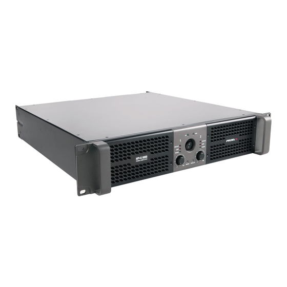
1 Safety Instructions: 1.1 Due to high voltage internal, please be careful during troubleshooting and maintenance course. Please read the user manual and this maintenance manual first. 1.2 Due to the wrong operation in checking and repairing course will results to ruined damage on some parts, so please operate follow this manual. 1.3 The maintenance person must be ONLY a qualified professional personnel authorized by PROEL. 1.4 Don’t replace the key devices and adjust the adjustable potentiometers by yourself, it will change the parameter of the equipment. 1.5 Please cut off the power to guarantee the safety of the service person when repairing. 1.6 The devices marked in the drawing indicates a key device, please replace it ONLY with a spare part specified by ...
Technical Specification MODEL HPX900 HPX1200 HPX2400 HPX2800 Power 8 ohm * 200 W 300 W 450 W 600 W Power 4 ohm * 300 W 450 W 800 W 1000 W Power 2 ohm ** 450 W 600 W 1200 W 1400 W Power BRIDGE 8 ohm * 400 W 600 W 900 W 1200 W Power BRIDGE 4 ohm ** 900 W 1200 W 2400 W 2800 W Output Stage Class AB Class AB Class H Class H Frequency response (+0/‐0.5 dB 20 Hz ‐ 20 KHz 20 Hz ‐ 20 KHz 20 Hz ‐ 20 KHz 20 Hz ‐ 20 KHz Input Sensitivity (nominal) +2.3 dBu / 1.0 Vrms...
5 HPX900 Malfunction Analysis on Power Supply 5.1 Circuit Diagram of SMPS: 5.2 Malfunction Analysis on SMPS: Sequence Circuit to Most Probably Failures No. check ‐ The AC fuse on the rear panel was burnt when connected the electricity: check the RT1 varistor device and the other line filter device to see if there is short circuit. ‐ RL1 Relay does not pull‐in and the thermistor NPTR1 is burnt so the Line Filter and 1 ...
Page 9
results to blocking and high‐current. On/Off ‐ The amplifier can not start and there is shock sound when shutdown: 3 Anti‐shock mainly check the device of this circuit, see whether the detached Circuit photocoupler OP1/817, Q37, Q38 is damaged or not; ‐ Fans do not work. Fan Speed ‐ Fast rotating. 4 Control Circuit ‐ It is easily to go into over‐heat protection if the fans don’t speed up after the module temperature increasing. ...
6 HPX900 Malfunction Analysis on Amplified Part 6. 1 Circuit Diagram of Amplifier ...
Page 11
6.2 Malfunction Analysis on Amplified Part Sequence Circuit Function Failure No. ‐ Power supply protection: Any of the short circuits of power output transistor (CH1/Q2, Q3, Q10, Q11, CH2/Q19, Q20, Q24, Q25) will cause the high current and power supply protection; ‐ Amplifier protection: +15 V/‐15V is derived from the current limiting of R31, R40 and D3, D4, if the power supply is abnormal it will lead to the DC output, amplifier will go into protect status; ‐ Clip limit doesn’t work – check whether the devices of D7, D8, D9, Class AB Power D40, LED1, R22 is damaged or not; 1 Output ‐ Amplifier self‐excitation – check whether the device of C3, C7, C8, C10, C14 was turn bad. ‐ Crossover distortion : check whether the BE voltage of the negative‐positive half‐wave power transistor is <0.2V or not, then check the value of temperature compensation transistor Q and resistance (R25, R26, R13) is changed; ‐ IC/5532 damaged, unbalanced of the of positive and negative bias voltage, has DC output and power amplifier goes into protection. Overload/ ‐ Output short‐circuit and no protection, 2 Short‐circuit ‐...
7 HPX1200/2400/2800 Malfunction Analysis on Aux Power Supply Board 7.1 HPX1200/2400/2800 Circuit Diagram of Aux power supply Module 7.2 Malfunction Analysis on Aux power supply Sequence Circuit Failure No. Function ‐ STY LED is off; the equipment is unavailable to start. ‐ Check the circuit, see if the CN1 pin and the copper foil of Aux Power Supply is broken; ‐ When amplifier connects to power supply, the Aux Power Supply Aux Power 1 (self‐activated switch) will start to work, provide two group standby Supply Board ...
8 HPX1200/2400/2800 Malfunction Analysis on SMPS CONTROL Circuit 8.1 Circuit Diagram of SMPS CONTROL 8.2 Malfunction Analysis on SMPS CONTROL Module Circuit Sequence Circuit Failure No. Function ‐ The equipment is unavailable to start; ‐ Protection function will be activated when in low impedance output; 1 SMPS Control ‐ Cyclic protection of the switch power; ‐ Delay start, over‐voltage PROT, low‐voltage PROT and over current PROT. Repairing Guide: 1) When repairing the control board, you can cut every protect circuit gradually found the defective area! ...
9 HPX1200 Malfunction Analysis on SMPS. 9.1 Circuit Diagram of SMPS 9.2 HPX1200 Malfunction Analysis on SMPS: Sequence Circuit Failure No. Function ‐ The AC fuse on the rear panel was burnt when connected the electricity: check the RT1 varistor device and the other line filter device to see if there is short circuit. Line Filter and 1 ‐ RL1 Relay does not pull‐in and the thermistor NPTR1 is burnt so the the Soft‐start amplifier can not start. ...
Page 15
VCC,‐VCC then try to start, if it is normal, it means short‐circuit in amplified part, check the amplified circuit, otherwise it is the failure of SMPS; 3) Power supply protection means – all the indicator lights on the panel lit and then immediately black out; ...
10 HPX1200 Malfunction Analysis on Amplified Part 10. 1 Circuit Diagram of Amplifier ...
Page 17
10.2 Malfunction Analysis on Amplified Part Sequence Circuit Function Failure No. ‐ Power supply protection: Breakdown of any one power transistor will cause a short circuit and results to high current protection. ‐ Amplifier protection: +15 V/‐15V if the power supply is abnormal will lead to the DC output, amplifier will go into protection status; Class AB Power 1 ‐ No clip limit; Output ‐ Amplifier self‐excitated; ‐ Cross‐over distortion; ‐ IC/5532 damaged, unbalanced of the of positive and negative bias voltage, has DC output and power amplifier goes into protection. ...
11 HPX2400/2800 Malfunction Analysis on SMPS 11. 1 Circuit Diagram of SMPS ...
Page 19
11.2 Malfunction Analysis on SMPS: Sequence Circuit Function Failure No. ‐ The AC fuse of the rear panel is burnt when connected the electricity‐check the RT1 device and line filter device to see if there is short circuit. Line ‐ There is smoke but it can still work while output power, check 1 Filter/Soft‐start/ whether the thermistor/ NPTR1 was burnt caused by the relay didn’t Rectification pull‐in; ‐...
12 HPX2400/2800 Malfunction Analysis on Amplified Part 12. 1 Circuit Diagram of Amplifier ...
Page 21
12.2 HPX2400/2800 Malfunction Analysis on Amplifier: Sequence Circuit Function Failure No. ‐ Power supply protect: Breakdown of any one power transistor will cause a short circuit and results to high current protection. ‐ Amplifier protection: +15 V/‐15V if the power supply is abnormal will lead to the DC output, amplifier will go into protection status; Class AB Power 1 ‐ No clip limit; Output ‐ Amplifier self‐excitated. ‐ Cross‐over distortion; ‐ IC/5532 damaged, unbalanced of the of positive and negative bias voltage, has DC output and power amplifier goes into protection. ...
13 HPX900/1200/2400/2800 Input Board 13. 1 Circuit Diagram of Input 13.2 Malfunction Analysis on Input Board Sequence Circuit Function Failure No. ‐ Poor connection in SW1 will cause the parallel and bridge indicator Stereo / Parallel does not shine; 1 / Bridge Switch ‐ Poor connection in SW1 will caused no output in one channel when Circuit amplifier in stereo, parallel or bridge mode; Bass Boost ‐ Poor connection of SW2 will cause no bass increase in CH1 or CH2 2 Circuit ‐ When increase the bass will cause the sound distortion; Sensitivity ‐ Poor connection of SW3 will cause the unbalanced output of left 3 Switch Circuit ...
Repair Guidelines: 1) There is still large signal output when in protection circuit, increase the volume and the signal source and then detect the output waveform by opening oscilloscope or multimeter, adjust the output waveform to minimum through VR1/VR2 when the amplifier start self‐protection. Note: Debugging must be done before the protection LED is off, you can repeat the debugging in interval. 14 Special Notes ...
Need help?
Do you have a question about the HPX Series and is the answer not in the manual?
Questions and answers