
Related Manuals for PROEL ACDT180V


Summary of Contents for PROEL ACDT180V
- Page 1 ACDT180V Amplifi catore PA combo PA combo amplifi er MANUALE UTENTE proelgroup.com...
-
Page 3: Precauzioni D'uso
Precauzioni d’uso Questo simbolo, ove compare, segnala la presenza di un voltaggio pericoloso non isolato all’interno del corpo dell’apparecchio – voltaggio suffi ciente a costituire un rischio di folgorazione. AVVERTENZA: Per ridurre il rischio di folgorazione, non rimuovere il Questo simbolo, ove appare, segnala, coperchio (o il pannello posteriore). -
Page 4: Istruzioni Di Sicurezza In Dettaglio
• Per evitare il danneggiamento del cavo d’alimentazione libreria o in altri luoghi a spazio ristretto dell’apparato, assicurarsi che questo non venga calpestato o • PROEL S.P.A. declina ogni responsabilità in caso di scorretta schiacciato da oggetti pesanti. installazione dell’unità. -
Page 5: Table Of Contents
Sommario Precauzioni d’uso................. . .3 Istruzioni di sicurezza in dettaglio . -
Page 6: Introduzione
Introduzione Grazie per aver scelto un prodotto Proel e della fi ducia riposta nel nostro marchio, sinonimo di professionalità, accuratezza, elevata qualità ed affi dabilità. Tutti i nostri prodotti sono conformi alle normative CE per utilizzazione continua in impianti di diff usione sonora. -
Page 7: Pannello Frontale
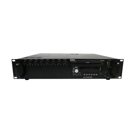
Pannello frontale fi g. 1 Interruttore d’accensione Controllo generale del volume (MASTER) Questa manopola è usata per controllare il volume di uscita. Controlli di tono I controlli di tono svolgono un intervento di +/- 10 dB nello spettro delle frequenze dei bassi ed acuti, per- mettendo di eff ettuare una corretta equalizzazione del segnale riprodotto. -
Page 8: Pannello Posteriore
Pannello posteriore fi g. 2 Presa d’ingresso per alimentazione di rete (con fusibile) Fusibile di protezione Protegge il dispositivo da eventuali sbalzi di tensione della rete di alimentazione e può essere sostituito. Selettore per alimentazione di rete 230/117Vca 50/60Hz Ingressi INPUT1 ~ INPUT4: Connettore d’ingresso COMBO/XLR Ingresso a morsetto estraibile euroblock Dip-switch:... - Page 9 Pannello posteriore Ingresso AMP IN – Uscita PRE OUT Di serie l’ingresso È possibile ottimizzare il segnale da MAIN IN è amplifi care interponendo tra i due collegato con terminali un’unità esterna l’uscita PRE OUT (es. equalizzatore, processore ecc.). con un ponticello. Per il collegamento riferirsi alla fi gura.
-
Page 10: Installazione
Installazione - connessioni d’ingresso Connessione microfono/base microfonica Qualunque tipo di microfono volete impiegare, utilizzate sempre un cavo schermato. Riferendosi alla (fi g.2 rif.4), settare il livello d’ingresso a livello MICRO, PIN1 a ON. Nota: se la base microfonica è attiva selezionare il livello LINEA PIN1 a OFF. Per applicazioni tipo parlato si consiglia di settare il PIN3 su ON. - Page 11 Installazione - connessioni d’uscita Attenzione Per prevenire il rischio di contatto con scariche elettriche non toccare mai le uscite dell’amplifi ca- tore quando esso è in funzione. Per accedere ai morsetti di connessione degli altoparlanti (fi g.2 rif.13), rimuovere il coperchio di protezione svitando le rispettive viti. Linea ad impedenza costante Per ottenere una linea a impedenza costante, collegare i due terminali rispettivamente al morsetto COM e a quello contrassegnato con il valore d’impedenza di linea desiderato (4, 8, 16Ω) (fi g.2 rif.13).
-
Page 12: Uso Del Lettore Cd/Mp3/Usb/Sd-Mmc/Tuner
Lettore CD/MP3/USB/SD-MMC/TUNER Caricatore CD È del tipo slot-in. Se si inserisce un CD quando l’unità è spenta, il lettore si accenderà automaticamente e partirà la riproduzione del CD. Display LCD Indica le modalità di funzionamento con diff erenti colori. Manopola Questa manopola è... - Page 13 Lettore CD/MP3/USB/SD-MMC/TUNER Tasti di selezione sorgente audio (USB/Card/CD/AM/FM) Questi tasti servono a selezionare la sorgente audio tra USB, Card, CD, AM, FM. Premere il tasto della sor- gente audio desiderata: automaticamente il lettore entrerà nella modalità corrispondente ai controlli della sorgente selezionata.
-
Page 14: Risoluzione Dei Problemi
Risoluzione dei problemi Il led non si accende con l’interruttore di accensione su ON • Controllare che la spina sia inserita. • Controllare che il fusibile sia funzionante. La ventola non gira • Controllare che la spina sia inserita. • Controllare che il fusibile sia funzionante. -
Page 15: Caratteristiche Tecniche
Specifiche tecniche Potenza di uscita RMS 180/240MAX Ingressi 4 x Mic.bilanciato 1.5mV / 600Ω (con Phantom 48V) Line 100mV / 5KΩ Aux/Tuner/Tape/CD 150mV / 10KΩ Telephone / Emergency Guadagno variabile - 600Ω Risposta in frequenza (+/- 3dB) 50Hz – 16.5KHz Controllo toni Bassi / Alti Uscite... -
Page 16: Esempi Di Possibili Connessioni
Esempi di possibili connessioni ITALIANO... -
Page 17: Important Safety Instructions
Important safety instructions This symbol is intended to alert the user of the presence of uninsulated dangerous voltage within the product enclosure that may be of suffi cient magnitude to constitute a risk of electric shock to persons. AVVERTENZA: Per ridurre il rischio di folgorazione, non rimuovere il This symbol is intended to alert the user of coperchio (o il pannello posteriore). -
Page 18: Detailed Safety Instructions
Before any unit relocation please control the unit is turned off . room. The power cord must be unplugged by the wall outlet, and all the • PROEL S.P.A. is not responsible for any damage that occurs due to connections wires should be disconnected as well. a wrong unit installation. -
Page 19: Table Of Contents
Table of contents Important safety instructions ..............17 Detailed safety instructions . -
Page 20: Introduction
Introduction Thank you for choosing one of Proel products, and for your confi dence towards our brand, synonymous of professionalism, accuracy, high quality and reliability. All our products are CE approved and designed for continuous use in professional installation systems. -
Page 21: Front Panel
Front panel fi g. 1 Main switch power Master volume control Such key allows the output volume control. Tones control Tone control are possible for frequency interval between o +/- 10 dB for low and acute frequency band and ensure the correct reproduced signal equalizing . Inputs level control From 1 up to 5 Led Level indicator - Vu meter It indicates the output signal level . -
Page 22: Rear Panel
Rear panel fi g. 2 Main Power supply plug ( with fuse) Protection Fuse It protects the unit against eventual power supply voltage variation. It can be replaced. Main power supply voltage selector 230/117Vca 50/60Hz Inputs INPUT1 ~ INPUT4: COMBO/XLR Input connector Euro block terminal –... - Page 23 Rear panel Input AMP IN – Output PRE OUT Standard It is possible to optimize the confi guration amplifi er signal setting an external MAIN IN input unit ( so as un equalizer processor, is connected to etc..) between the two terminals . PRE OUT output For connections revert to the throughout a...
-
Page 24: Installation
Installation - input connections Microphone/ microphone stands connections Use only shielded cable with any kind of microphone used. Revert to (fi g.2 ref.4), set input level to MICRO level, PIN1 position ON. Note: if the microphone stand is active, select LINE level PIN1 position OFF Advice: For use for speech, set PIN3 on position ON. - Page 25 Installation - output connection Attention To prevent against electrical shock, Do never touch the amplifi er outputs when powered. To access to loudspeakers terminal connections (fi g.2 ref.13) unscrew to remove the unit cover. Line at constant impedance In order to have a line at constant impedance, connect respectively the two terminal to COM and the one with the impedance line value selected (4, 8, 16Ω) (fi g.2 ref.13).
-
Page 26: Cd/Mp3/Usb/Sd-Mmc/Tuner Player
CD/MP3/USB/SD-MMC/TUNER player CD Loader It uses slot-in way. When turning off the unit and putting the CD in, the player will automatically turn on and play. LCD Display It indicates the operation status by diff erent colors. Knob This knob is used to adjust the volume and turn on/off the CD player. Press this button, the player turns on, at this time the light(ring) around the knob will light up and indicate the operation status. - Page 27 Lettore CD/MP3/USB/SD-MMC/TUNER Audio Source Selection buttons(USB/Card/CD/AM/FM) These buttons are used to select the Audio Source, such as USB, Card, CD, AM, FM. Press the buttons as you need, you will get the Audio Source that you want, and enter into the corresponding input control. Menu It provides two kinds of function setting.
-
Page 28: Troubles And Solutions
Troubles and solutions LED does not light when POWER switch is ON • Check that the plug is connected. • Check the fuse status. No Fan action • Check that the plug is connected. • Check the fuse status. No sound •... -
Page 29: Technical Characteristics
Specifications Output Power RMS 180/240MAX Inputs 4 x Mic.balanced 1.5mV / 600Ω (with 48V Phantom) Line 100mV / 5KΩ Aux/Tuner/Tape/CD 150mV / 10KΩ Telephone / Emergency Variable gain - 600Ω Frequency range (+/- 3dB) 50Hz – 16.5KHz Tone controls Low / High Outputs Speakers 100/70/50V - 16/8/4Ω... -
Page 30: Examples Of Possibile Connections
Examples of possibile connections ENGLISH... - Page 32 PROEL S.p.A. (World Headquarters - Factory) Via alla Ruenia, 37/43 64027 Sant’Omero (TE) - ITALY Tel. +39 0861 81241 Fax +39 0861 887862 proelgroup.com...
Need help?
Do you have a question about the ACDT180V and is the answer not in the manual?
Questions and answers