Advertisement
Advertisement
Table of Contents

Subscribe to Our Youtube Channel
Related Manuals for PROEL AMP 120Z4


Summary of Contents for PROEL AMP 120Z4
- Page 1 INSTRUCTION MANUAL PA Zone Mixer/Amplifier AMP 120Z4 / 180Z4 / 240Z4...
-
Page 2: Important Safety Instructions
IMPORTANT SAFETY INSTRUCTIONS To reduce the risk of electric shock do not remove cover (or back panel). No CAUTION: user serviceable parts inside. Refer servicing to qualified personnel only. To reduce the risk of fire or electric shock, do not expose this apparatus to WARNING: rain or moisture. -
Page 3: Detailed Safety Instructions
Sentences preceded by symbol contain important safety instruction. Please read it carefully. DETAILED SAFETY INSTRUCTIONS. Water and moisture: This apparatus should not be used near water (i.e. bathtub, kitchen sink, swimming pools, etc.) Ventilation: This apparatus should be placed in a position that doesn’t interfere with correct ventilation. This unit, for example, should not be placed on a bed, sofa cover o similar surfaces that could cover ventilation openings, or placed in a built-in installation, such a bookcase or a cabinet that could block air flow trough ventilation openings. - Page 4 Objects or liquid entry inside the unit: Be careful that no objects fall or liquid is spilled inside the unit through ventilation openings. Safe power line use: • Keep firmly the plug and the wall outlet while disconnecting the unit from AC power. •...
-
Page 5: Monitor Output
Don’t place this unit in a bookshelf o in other places with small room. • PROEL S.P.A. is not responsible for any damage that occurs due to a wrong unit installation. Thank you for choosing one of Proel products, and for your confidence towards our brand, synonymous of professionalism, accuracy, high quality and reliability. -
Page 6: Front Panel Description
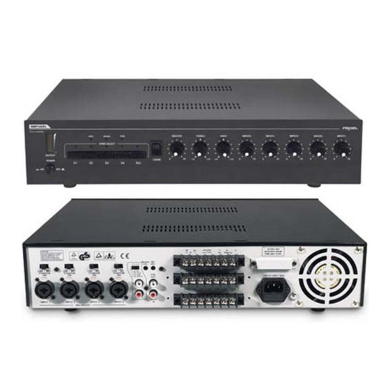
• Protection circuit LED • Telephone-line signal input • Bass and Treble EQ controls • Output volume control • Five independent level controls for input signals 3. FRONT PANEL DESCRIPTION fig. 1 1) POWER - Power switch. 2) P.I. - Power LED. This LED is lit when the power switch is on. 3) LED volume meter. -
Page 7: Rear Panel Description
4. REAR PANEL DESCRIPTION fig. 2 IEC AC power socket. Telephone - paging input. Priority function activation terminals. Monitor output terminals. Zone 1, 2, 3 and 4 (100V outputs ) output terminals. Speakers outputs for constant impedance/constant voltage connection. INPUT 1-2-3-4 sensitivity selectors. INPUT 1-2-3-4 connectors. - Page 8 To choose the source type to be connected, please use selectors (fig. 2 ref. 7): LINE position for AM/FM tuners, CD players etc., MIC position for dynamic microphones and PHANTOM position for condenser microphones. INPUT1 is provided of VOX function. When this input receives a signal, this signal has priority over all the other inputs;...
- Page 9 • MAIN IN and PRE OUT. MAIN IN input is connected to PRE OUT output by a jumper. It’s possible to obtain a better performance of amplified sound inserting an external unit (i.e. equalizer, processor etc.). Please see the following picture for proper wiring. •...
- Page 10 2. Output connections Attention To prevent the risk of electric shock, never touch amplifier outputs when the amplifier is turned on. • Speakers connections. To access to speaker connection terminals remove the protection cover unscrewing the correspondent screws (fig.2 ref. 5, ref. 6). This amplifier may be used both with constant impedance speakers (4, 8, and 16 Ω) and with constant voltage speakers (25V, 70, and 100V).
- Page 11 Constant voltage line If you’re using a constant voltage line, connect either the 70, or 100V to the “+” side of speaker system, and connect COM to “-“ side of the speaker (fig.2 rif.6).
- Page 12 − For discrete line installation (zone system), each zone is independent from the other, connect speakers terminals to COM and to the desired zone number (fig. 2 ref. 5). − If you’re using a zone selector, you won’t be able to use constant impedance speakers, since the line is set at 100 V constant voltage.
- Page 13 • MONITOR output connection This output allows you to connect a speaker (monitor), driven from the unit internal 1W amplifier, reproducing AUX IN signals. − Connection is obtained using rear panel terminals (fig. 2 ref. 4). − Output signal is set by AUX IN volume control, or by rear panel Monitor vol.
- Page 14 7. CHIME switch The unit has a chime built in generator, that can be activated by the front panel switch (fig. 1 ref. 13), to be used for paging beginning or end. When chime is activated it has priority over all the other signals and its volume is set by INPUT1 and MASTER controls.
- Page 15 7. Technical specifications Model AMP120Z4 AMP180Z4 AMP240Z4 RMS / MAX (W) output 120 W / 150 W 180 W / 240 W 240 W / 300 W power Constant impedance 4Ω, 8 Ω, 16Ω outputs Constant voltage 25V, 70V, 100V outputs 4 COMBO XLR / 6.3 mm jack input Inputs connectors...
- Page 16 8. Typical hookup diagram...
- Page 17 Directive 73/23/EEC (Low Voltage) and following modifications 93/68/EEC, as the following standard: EN 60065:1998 Proel SpA pursue a policy of continuous research and development. Proel SpA reserve the right to modify product circuitry and appearance at any moment, without prior notice.
- Page 18 PROEL S.p.A (World Headquarters - Factory) Via alla Ruenia 37/43 64027 Sant’Omero (Te) – Italy Tel: +39 0861 81241 Fax: +39 0861 887862 E-mail: info@proelgroup.com installation.proelgroup.com...
Need help?
Do you have a question about the AMP 120Z4 and is the answer not in the manual?
Questions and answers