
Related Manuals for PROEL AMP120XL


Summary of Contents for PROEL AMP120XL
- Page 1 MANUALE UTENTE – USER’S MANUAL Amplificatore PA Integrato PA Mixing Amplifier AMP30XL / AMP60XL / AMP120XL...
- Page 3 1. PRECAUZIONI D’USO AVVERTENZA:Per ridurre il rischio di scossa elettrica, non rimuovere il coperchio (o il pannello posteriore). All’interno non sono contenute parti riparabili dall’utente; affidare la riparazione a personale qualificato. ATTENZIONE: Per ridurre il rischio d’incendio o di scossa elettrica, non esporre questo apparecchio alla pioggia o all’umidità.
- Page 4 Le note precedute dal simbolo contengono importanti informazioni sulla sicurezza: leggerle con particolare attenzione. ISTRUZIONI DI SICUREZZA IN DETTAGLIO. Acqua ed umidità: L’apparecchio non deve essere utilizzato in prossimità di acqua (per es. vicino a vasche da bagno, lavelli da cucina, in prossimità di piscine ecc.). Ventilazione: L’apparecchio deve essere posto in modo tale che la sua collocazione o posizione non interferisca con l’adeguata ventilazione.
- Page 5 Ingresso di liquidi o oggetti: Si deve prestare attenzione che non cadano oggetti e non si versino liquidi nel corpo dell’apparecchio attraverso le griglie. Uso sicuro della linea d’alimentazione: • Quando si scollega l’apparato dalla rete tenere saldamente sia la spina che la presa. •...
- Page 6 • PROEL S.P.A. declina ogni responsabilità in caso di scorretta installazione dell’unità. Grazie per aver scelto un prodotto Proel e della fiducia riposta nel nostro marchio, sinonimo di professionalità, accuratezza, elevata qualità ed affidabilità. Tutti i nostri prodotti sono confermi alle normative CE per utilizzazione continua in impianti di diffusione sonora.
-
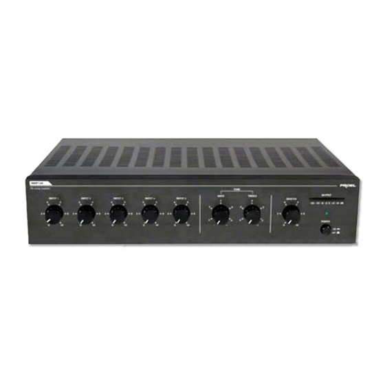
Page 7: Pannello Frontale
• Un ingresso AUX RCA stereo con sensibilità selezionabile CD/TAPE/TUNER. • Quattro uscite di cui una a impedenza costante 4Ω e tre a tensione costante (25, 70, 100 V). • Un’uscita PRE OUT • Un’uscita TAPE OUTPUT. • Selettore tensione d’alimentazione (115 – 230 V). •... -
Page 8: Pannello Posteriore
4. PANNELLO POSTERIORE fig.2 1) Selettore della tensione di alimentazione 2) Uscita TAPE OUTPUT 3) Ingresso AUX INPUT (INPUT5) 4) Ingressi INPUT1 ÷ INPUT4 5) Vano porta-fusibile 6) Presa per cavo di alimentazione 7) Morsetti per alimentazione in continua 8) Morsetti d’uscita 9) Selettore di sensibilità... -
Page 9: Installazione
5. INSTALLAZIONE 1. Connessioni d’ingresso • Gli ingressi INPUT1, INPUT2, INPUT3, INPUT4 sono di tipo XLR universale bilanciato, utilizzabili per il collegamento sia di microfoni dinamici a bassa impedenza (30-600Ω), sia di microfoni a condensatore con alimentazione phantom a 24V , sia di sorgenti audio con uscita del segnale livello “linea”... - Page 10 • Ingresso AUX INPUT (INPUT 5). Le prese R e L consentono l’ingresso del canale destro (R) e sinistro (L) attraverso connettori RCA. A quest’ingresso è possibile collegare una sorgente sonora esterna. • Ingresso MAIN IN e uscita PRE OUT. L’ingresso MAIN IN è...
- Page 11 • Morsetti d’ingresso DC 24V I due morsetti permettono all’unità di essere alimentata in corrente continua attraverso una sorgente esterna (es. generatore o batteria a 24V). In caso di mancanza improvvisa della tensione di rete l’unità passerà automaticamente all’alimentazione 24Vdc, garantendo quindi la continuità...
- Page 12 Linea ad impedenza costante Per ottenere una linea a impedenza costante (4Ω) collegare i due terminali rispettivamente al morsetto COM e 4Ω. − Al fine di garantire il massimo rendimento, l’impedenza totale degli altoparlanti collegati alla linea, deve essere uguale all’impedenza dell’uscita dell’amplificatore.
- Page 13 • Collegamento dell’uscita monitor da 1W Consente il collegamento di un altoparlante a 8 Ω (monitor), pilotato dall’unità tramite un amplificatore interno della potenza di 1 W, che riproduce i segnali presenti sugli ingressi INPUT4 e AUX INPUT miscelandoli . −...
- Page 14 − Il segnale d’uscita viene regolato esclusivamente dai controlli di volume degli ingressi INPUT4 e AUX INPUT. • Collegamento dell’uscita 0dB Consente il collegamento del segnale, miscelato, proveniente da INPUT4 e AUX INPUT a qualsiasi apparecchiatura esterna (fig.2 rif.12). − I morsetti possono essere...
- Page 15 6. Disattivazione della funzione VOX PRIORITY Dopo aver tolto le viti, sollevare il coperchio e individuare il connettore CN7 VOICE (rif .2) sulla scheda (rif.1), come indicato nelle foto seguenti:...
- Page 16 Di fabbrica il connettore CN7 è nella configurazione A (ENABLE): l’ingresso 1 è prioritario rispetto a tutti gli altri. Se si vuole escludere la funzione di priorità, settare il connettore CN7 nella Configurazione B (DISABLE): in questa configurazione tutti e 5 gli ingressi vengono miscelati. 6.
- Page 17 7. Caratteristiche tecniche Modello AMP30 AMP60 AMP120 Potenza d’uscita RMS / MAX 30/45 60/90 120/180 Uscita a tensione costante 25,70,100V Uscita a impedenza costante 4Ω INPUT 1~ INPUT 4: XLR Connettori d’ingresso AUX INPUT: RCA MAIN-IN: su morsettiera 4Ω su morsettiera 25, 70, 100V su morsettiera Connettori d’uscita PRE OUT su morsettiera...
-
Page 18: Esempi Di Connessione
8. ESEMPI DI CONNESSIONE... - Page 19 93/68/CEE, secondo il seguente standard: EN 60065:1998 La Proel SpA persegue una politica di costante ricerca e sviluppo, di conseguenza si riserva il diritto di apportare miglioramenti ai prodotti esistenti, senza preavviso e in qualunque momento. REV. 01 / 24-08...
-
Page 20: Important Safety Instructions
1. IMPORTANT SAFETY INSTRUCTIONS To reduce the risk of electric shock do not remove cover (or back panel). No CAUTION: user serviceable parts inside. Refer servicing to qualified personnel only. To reduce the risk of fire or electric shock, do not expose this apparatus to WARNING: rain or moisture. - Page 21 Sentences preceded by symbol contain important safety instruction. Please read it carefully. DETAILED SAFETY INSTRUCTIONS. Water and moisture: This apparatus should not be used near water (i.e. bathtub, kitchen sink, swimming pools, etc.) Ventilation: This apparatus should be placed in a way that his position doesn’t interfere with correct ventilation.
- Page 22 Objects or liquid entry inside the unit: Be careful that no objects fall or liquid is spilled inside the unit through ventilation openings. Safe power line use: • Keep firmly the plug and the wall outlet while disconnecting the unit from AC power. •...
- Page 23 Don’t place this unit in a bookshelf o in other places with small room. • PROEL S.P.A. is not responsible for any damage that occurs due to a wrong unit installation. Thank you for choosing one of Proel products, and for your confidence towards our brand, synonymous of professionalism, accuracy, high quality and reliability.
-
Page 24: Tape Output
• AUX RCA stereo CD/TAPE/TUNER input with selectable sensitivity. • Four discrete outputs. Constant impedance output (4Ω) and three constant voltage outputs (25V - 70 V – 100 V). • PRE OUT output. • TAPE OUTPUT. • Switchable power supply (115V – 230 V). •... -
Page 25: Rear Panel Description
4. REAR PANEL DESCRIPTION fig.2 1) AC power selector. 2) TAPE OUTPUT connectors. 3) AUX INPUT (INPUT5) connectors. 4) INPUT1 ÷ INPUT4 connectors. 5) Fuse folder. 6) IEC AC power socket. 7) DC power terminals. 8) Speaker output terminals. 9) AUX INPUT sensitivity selector. 10) COM terminal for outputs 11), and 12). -
Page 26: Installation
5. INSTALLATION Inputs wiring • INPUT1, INPUT2, INPUT3, and INPUT4 have a balanced XLR connector, useful to connect both low impedance microphones (30- 600Ω), both condenser microphones with 24V phantom power supply, both line level audio sources (i.e. AM/FM tuner, cassette deck, CD player, etc.). - Page 27 • AUX INPUT (INPUT 5). L e R RCA input connectors allow the input of a stereo signal by left (L) and right (R) inputs. This stereo input is useful to connect a stereo external audio source. • MAIN IN input and PRE OUT output. MAIN IN input is connected to PRE OUT output by a jumper.
- Page 28 • 24V DC input terminals These two terminals allow the unit to be DC powered by an external power source (i.e. 24V generator or battery). In case of AC power fault or black out, the unit will be powered by 24 V DC, with automatic and silent switchover to backup power.
- Page 29 Constant impedance line. To use this amplifier with a constant impedance line (4Ω), please connect the COM terminal to the negative post of your speaker, and connect the 4Ω terminal to the positive post. − To obtain the best performances, the total speakers impedance connected to the line, should be equal to the amplifier output impedance.
- Page 30 • 1W monitor output connection This terminal allows an 8 Ω speaker (monitor) connection, driven by the 1 W internal power internal amplifier, reproducing blended INPUT4 and AUX INPUT signals. − The connection is made using terminals on unit rear panel (fig. 2 ref.
- Page 31 − Output signal is managed by INPUT4 and AUX INPUT volume controls only. • 0dB output connection It allows the connection of blended INPUT4 and AUX INPUT signals to any external device (fig. 2 ref. 12). − Terminals may be connected to an external unit with unbalanced input, higher than 600 Ω...
- Page 32 6. VOX PRIORITY function deactivation Once removed the screws, open the cover and detect the CN7 VOICE connector (ref.2), on the board (ref.1) as showed in the following pictures:...
-
Page 33: Operation
The default configuration of the CN7 connector is A (ENABLE): Input 1 is priority compared to all the other inputs. For exclude the priority function, set the CN7 connector to B configuration (DISABLE): in this configuration all the 5 inputs are mixed. 6. -
Page 34: Technical Specifications
7. Technical specifications Model AMP30 AMP60 AMP120 RMS / MAX (W) output 30/45 60/90 120/180 power Constant voltage outputs 25,70,100V Constant impedance output 4 Ω INPUT 1~ INPUT 4: XLR connectors, Inputs connectors AUX INPUT: RCA MAIN-IN: on terminal board 4Ω: on terminal board 25, 70, 100V: on terminal board Outputs connectors... - Page 35 8. TYPICAL HOOKUP DIAGRAMS...
- Page 36 93/68/EEC, as the following standard: EN 60065:1998 Proel SpA pursue a policy of continuous research and development. Proel SpA reserve the right to modify product circuitry and appearance at any moment, without prior notice. REV. 01 / 24-08...
- Page 37 Note _______________________________ _______________________________ _______________________________ _______________________________ _______________________________ _______________________________ _______________________________ _______________________________ _______________________________ _______________________________ _______________________________ _______________________________ _______________________________ _______________________________ _______________________________ _______________________________ _______________________________ _______________________________ _______________________________ _______________________________ _______________________________...
- Page 38 _______________________________ _______________________________ _______________________________ _______________________________ _______________________________ _______________________________ _______________________________ _______________________________ _______________________________ _______________________________ _______________________________ _______________________________ _______________________________ _______________________________ _______________________________ _______________________________ _______________________________ _______________________________ _______________________________ _______________________________ _______________________________...
- Page 40 PROEL S.p.A. (World Headquarters - Factory) Via alla Ruenia 37/43 64027 Sant’Omero (Te) – Italy Tel: +39 0861 81241 Fax: +39 0861 887862 E-mail: info@proelgroup.com installation.proelgroup.com...
Need help?
Do you have a question about the AMP120XL and is the answer not in the manual?
Questions and answers