GRAUPNER mz-24 HoTT Operating Instruction
2.4ghz radio system
Hide thumbs
Also See for mz-24 HoTT:
- Operating instruction (106 pages) ,
- Operating instructions manual (102 pages) ,
- Manual (28 pages)

Related Manuals for GRAUPNER mz-24 HoTT


Summary of Contents for GRAUPNER mz-24 HoTT
- Page 1 No. S1006 OPERATING INSTRUCTION Prior to use, please read this manual thoroughly. Keep this manual in a convenient place for quick and easy reference.
-
Page 2: Table Of Contents
Contents 8. S.Limit 42~44P • Before Use 9. S.MIX 44~45P • Introduction 10. THR.MIX 45~50P • Support and Service 11. PRO.MIX 50~51P • Openhobby A/S Center 12. Trainer 1. Box Contents 51~52P 13. PIT >> RUDD 2. Flying Safety 14. Telemetry 3. -
Page 3: Introduction
Graupner/SJ. This Graupner/SJ mz-24 HoTT radio system is used to airplane, helicopter and glider and should be manual contains instructions for safety, operation and maintenance. It is essential to read and follow all the instructions and warnings in the manual, prior to assembly, setup or use, in order to operate a perfect choice for anyone who needs a high quality radio. -
Page 4: Specification
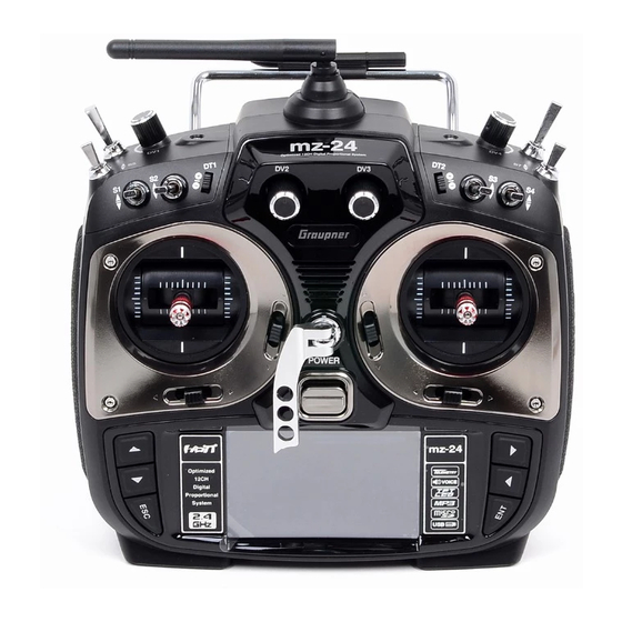
6. TRANSMITTER CONTROL IDENTIFICATION 4. SPECIFICATION ANTENNA Transmitter mz-24 Receiver GR-24 Frequency band 2.4~2.4835GHz 2.4~2.4835GHz Modulation FHSS FHSS S3 SWITCH S5 SWITCH Output power 100mW S2 SWITCH Current drain approx 125mA approx 70mA S1 SWITCH S4 SWITCH Operating voltage 3.4V~6V 3.6V~8.4V POWER SWITCH NECKSTRAP LUG... -
Page 5: Binding
7. BINDING 1. You must bind the receiver to the transmitter before the receiver will operate. Binding teaches the receiver the specific code of the transmitter so that it will only connect to it’s corresponding transmitter. If you turn on transmitter’s power before binding, the warning message appears on transmitter LCD page, which announce transmitter is not bound. -
Page 6: Base Menu (Helicopter, Airplane, Gilder)
BASE MENU (Helicopter, Airplane, Gilder) 1. Model select It is used to add or select model. Touch Model Sel icon in base menu to access Model sel menu Touch 1-2. NEW This function is use to create the new model or exchange the current model to others. There is 2 methods of Manual setting and Wizard setting. - Page 7 In accordance with model type that you selected, swash type function or wing type function is accessed. Below picture shows the example for wing type in airplane. Select the desired wing type, tail type and power type in turn. If all procedures have been done correctly, all Touch types that you selected appear on the page.
- Page 8 In accordance with model type that you selected, swash type function or wing type func- tion is accessed. Below picture shows the example for swash type in helicopter. Select the desired swash type, power type and set reverse function, EPA function, D/R EXP function, Pit CRV function, Thr.CRV function, GYRO function, Thr.HOLD function, FAILSAFE function in turn.
- Page 9 Touch Touch Touch Touch Touch Touch Touch Touch Touch Touch Touch Touch Touch Touch Touch Touch...
- Page 10 Touch Touch Touch Touch Touch Touch 1-3. INT.M (Internal Model) It is used to copy the model memory in SD Card into the model list of transmitter. To make use of INT.M function, you need SD Card that has the programmed model file. If you put SD Card into SD Card slot on the back of transmitter, “SD Card”...
- Page 11 1-4. EXT.M (External Model) This function is used to copy the model in transmitter into SD Card. In order to use EXT.M function, you need to plug SD Card into SD Card slot on the back of transmitter. When it is plugged into the slot, “SD Card”...
-
Page 12: Cpy(Model Copy)
2. Model type 1-6. CPY(Model Copy) It is used to reset the model type. Please note that all the value, excepting for model name, is reset when “Model type” is reset. Touch “Model type” icon on base menu page to call the The Copy function is used to copy the programmed values of a model into the other model. - Page 13 Touch Touch Touch Touch Touch Touch Touch 3. E.P.A E.P.A is used to adjust Servo operation angle and limitation for each channel. Touch “E.P.A” icon on the base menu page to call E.P.A setup page. “Limit” and “travel” can be set individ- ually.
-
Page 14: Reverse
Touch Touch Touch Touch Touch Touch 4. Reverse It is used to reverse the operation of an individual servo. Touch the “Reverse” icon in the base menu page to call the Reverse setup page. In “Reverse” page, you are able to reverse the operation of a servo. -
Page 15: Thr.cut
Touch Touch Touch Touch Touch Touch 6. THR.CUT This function is used to stop the operation of engine. THR.CUT function works from below one-third position of the full movement range of throttle stick. Touch “THR.CUT” icon in the base menu page to call the “THR.CUT” setup page. When touching “INH” icon in “ACT” line, you may change the value to “OFF”. -
Page 16: Tx Ctl
Touch Touch 7. TX ctl It consists of the multiple functions for a transmitter. It includes “BIND ON/OFF”, “TX OUT SET”, “RF ON/OFF”, “RF TYPE”, “RANG TEST”, and “DSC OUTPUT” functions. Touch “TX Touch ctl” icon to call the “TX ctl” setup page. Touch Touch - BIND ON/OFF... - Page 17 - TX OUT SET It is used to edit the receiver’s “out-channel” connected to each channel of transmitter as you want. For example, when “2 Elevator” function is used, the “CH3” and “CH8” out pins of receiver are used in the traditional channel setup, however, if the receiver’s CH4 pin is set for the transmitter’s CH3 using “TX OUT SET”...
- Page 18 Touch Touch - DSC OUTPUT It is used to set the number of channel when Trainer function is used with DSC jack. If 5 channels are used, PPM5 is recommended to use. To use more than 5 channels, choose the appropriate PPM for each condition.
-
Page 19: Timer
8. TIMER To set the model time, touch “MODE” icon and then select “UP” or “DOWN”. The default value Timer function may be set for any desired time ,i.e. model time, date, time, etc. Two independ- is UP. Timer may be set count-down or count-up operation with your choice. Count-up timer ent timers, TIMER1 and TIMER2, are provided for each model. - Page 20 Touch Touch Touch Touch After “ALARM” setup, you may set “START SW”. Touch “NULL” icon in “START SW” to call When START SW setup is completed, you may set RESET SW function. Touch the “NULL” “Select” message popup. Now, move the switch with your choice then this switch is set on/ icon in “RESET SW”...
- Page 21 Touch Touch Touch Touch Touch Touch After RESET SW is set, you may set “LAP SW” function. Touch “NULL” icon in “LAP SW” to Touch call “select” message popup. Now, move the switch with your choice then this switch is set on/ off switch for “LAP SW”...
- Page 22 After Timer 2 setup, touch “NEXT” icon on the right. You may call the page of the date/ time setup. Touch “SET” icon to activate it in blue and touch the desired value to activate in blue. With “INC” and “DEC” buttons, you may adjust the values for the date and time as the picture shown below.
-
Page 23: Failsafe
Touch Touch Touch Touch Touch Touch Touch 9. FAILSAFE When you bind your transmitter, you are programming the receiver with failsafe defaults. If connection is lost between the transmitter and receiver, the receiver immediately operates in those preprogrammed default positions. The default value is “Hold”... -
Page 24: Trim Step
10. TRIM STEP It allows you to check all function values of “Digital trim step”, “DT1”, “DT2”, ‘Digital volume”, and “Side slide”. Touch “Trim Step” icon in base menu page to call Trim Step setup page. The step value indicates the amount that the trim is moved in the range, 100, when operating Touch trim key one time. -
Page 25: Servo
Touch Touch Touch Touch Touch Touch Touch Touch 11. SERVO It is used to test a servo and check the servo movement in a graph. You are able to test the servo movement from 0.5sec to 5 sec with your choice. Touch “Servo” icon in the base page to call the servo setup page. -
Page 26: Ch Set
12. CH Set It is used to set the channel of a transmitter. The basic setup of the transmitter’s channel is Touch set differently depending on 3 different types (“model type”, “wing type”, and “swash type”) and mz-12 offers AUX channel to set the switch, volume, and side lever for your purpose. Touch “CH set”... -
Page 27: Out Swap 27~28P
Touch Touch Touch Touch Touch Touch Touch Touch Touch 13. Out Swap This function is used to edit the channel connection between transmitter and receiver. (It is similar to TX OUT SET function in TX ctl, but Out Swap function is operated without trans- mitting the setup data to a receiver unlike TX OUT SER function. -
Page 28: New
1-1 NEW This function is used when you wish to create new Q.LINK. If you may want to set for new Touch Q.LINK, touch the value in “Q.LINK” line to activate it in blue and touch “NEW” icon in the right to call “CTRL”... -
Page 29: Nam
Hold Hold Touch ldle-up1 ldle-up1 Touch ldle-up2 ldle-up2 ldle-up3 ldle-up3 Touch Touch Touch Hold ldle-up1 ldle-up2 ldle-up3 1-2 NAM 1-3 CPY It is used when to revise the name of “Q.LINK”. Touch the target value in “Q.LINK” to activate CPY function is used to copy the preset Q.LINK setup data into another Q.LINK. Touch the in blue. - Page 30 Touch Touch Touch Touch 2. D/R, EXP 1-4 Del D/R function is used to adjust the operation range of servos that is connected to all channels including aileron, elevator and rudder channels. You can assign them to numerous switches It is used to delete the unused Q.LINK. Touch the entry in Q.LINIK line that you want to delete and sticks EXP function is used to set D/R function to aileron, elevator and rudder channels to activate in blue and touch “DEL”...
- Page 31 After “D/R”, “EXP” setup, perform CTL setup. It is used to assign the switch to D/R, EXP function Touch “NULL” icon in CTL line to call “Select” message popup and move the switch that you want to use then that switch is set on/ off to switch and the switch direction setup page appears.
- Page 32 Touch Touch Touch Touch Touch Touch Touch Touch Touch Touch Touch Telemetry...
-
Page 33: Pit.crv
3. PIT.CRV TRIM This function adjusts the pitch operation curve in relation to the movement of the throttle stick for each condition Since pitch curve is closely related with Q.LINK setup, Q.LINK setup should precede PIT.CRV setup. Call Q.LINK setup page and check Q.LINK setup is completed Touch correctly and touch “BACK”... - Page 34 TRIM TRIM TRIM TRIM Touch Touch Touch Touch TRIM TRIM TRIM TRIM Touch Touch Q.LINK (idel-up2) TRIM TRIM TRIM TRIM Touch Touch Q.LINK (Hold) TRIM TRIM TRIM Touch Touch Telemetry...
- Page 35 If you touch OFF icon in Curve line, it is changed to ON and the operation curve is smoother. To set the pitch, throttle curve trim, touch “TRIM” icon in the top right to call the pitch, throttle curve trim setup page. Touch TRIM TRIM...
-
Page 36: Thr.crv
In FUNCTIOPN page, touch “THR.CRV” icon to call THR.CRV setup page. You need to mark the point on graph first and then adjust the operation curve with “DEC”, “INC”, X-axis and Y-axis buttons. Touch “ST OFF” to switch to “ST ON” then the throttle position line appears on graph. - Page 37 워드:63P TRIM TRIM TRIM TRIM 63-5W 이미지 수정 Touch Touch Touch TRIM TRIM TRIM TRIM Touch Touch TRIM TRIM TRIM TRIM Touch Touch TRIM TRIM TRIM Touch Touch Telemetry...
-
Page 38: Gyr/Gover
If you touch OFF icon in Curve line, it is changed to ON and the operation curve is smoother. NORMAL MODEL NAME 1 You may set the pitch, throttle curve trim by touching “TRIM” icon in the top right. The setup TRIM method is explained at PIT.CRV Touch... - Page 39 Gyro Gain, Governor, Governor RATE, Gyro Suppression are available in this function - Gyro Gain is used to adjust the sensitivity of gyro. “00%” is basically set and heading lock gyro is operated at over 40% of sensitivity. You may adjust sensitivity for each condition of Q.LINK.
-
Page 40: Thr.hold
Touch Touch Gyro Suppression TRIM Telemetry Touch 6. THR.HOLD This function is for powering down an engine or motor using a designated switch. Throttle hold has higher authority than any other flight mode. When you activate THR.HOLD, the throttle channel is driven to its programmed value. It is usually used to turn off an engine or hold in Touch idle position when helicopter’s auto rotation flight In function page, touch “THR.HOLD”... -
Page 41: Swash
Touch Telemetry Touch 7. SWASH Touch The swash function supports adjustment of the travel amount and direction of the aileron, elevator and pitch in Helicopter mode. Bind a helicopter to a receiver and set the travel amount and direction of the swash channels desirably Touch “SWASH” icon to call “SWASH” setup page. - Page 42 8. S.Limt (Swash Limit) It is used to have the channels of PITCH, AILE and ELEV operated for the circle movement of the stick and the channels of PITCH, AILE and EL have the travel limits according to the circle setup size. Servo EPA should be set over 100%, if the circle size is over 100% The Swash rotation function in the bottom is used to make the swash that mz-12 doesn’t support available by...
- Page 43 (RATE) (RATE) Touch Touch Touch Telemetry Touch Touch (RATE) (RATE) Touch Touch Touch (RATE) (RATE) Touch Touch Touch Touch Touch (RATE) (RATE) Touch Touch...
-
Page 44: Thr.mix
Touch Touch Telemetry Telemetry (RATE) Touch 10. THR.MIX Touch THR.MIX function prevents RPM decay when PITCH, AILE and ELEV inputs are given. This mix advances the throttle position with mix control to maintain RPM. This function can be adjusted for each condition of Q.LINK and three types is available (AILE>>THRO, ELEV>>THRO, RUDD>>THRO) AILE>>THRO: It can prevent RPM decay and maintain flight altitude of a helicopter while controlling aileron. - Page 45 11-1. Liner mixing type In FUNCTION page, touch “Prog.MIX” icon to call the prog.mix page. Touch “INH” icon in ACT line to switch to “ON” and touch “NONE” in MST line to call the mixing channel setup page. Touch and activate “NONE” icon and select the desired channel for the master by touching. Touch Now, touch and activate the left “NONE”...
- Page 46 Touch Touch Touch Touch Touch Touch Touch Touch Touch Touch Touch Touch...
- Page 47 Touch Touch Touch Touch Touch Touch Touch Touch Touch Touch Telemetry Touch Touch...
- Page 48 11-2. Curve mixing type In the prog.mix page, touch “NEXT” icon to call the next page and touch “INH” icon in the cross line of NO7 and ACT to switch to “ON”. Touch “NONE” in MST line to access the Touch channel selection page and touch and activate “NONE”...
- Page 49 Touch Touch Touch Touch Touch Touch Touch Touch Touch Touch Touch Touch...
-
Page 50: Trainer
Touch Touch 12. Trainer (Helicopter, Airplane, Gilder) mz-12 features a programmable trainer function. Two transmitters must be connected by Wireless or an optional DSC code. This function makes it possible for the instructor to choose which functions and channels are to be used for instruction. In FUNCTION page, touch “Trainer”... -
Page 51: Pit >>Rudd
Touch Touch 13. PIT >>RUDD This function is used to correct the unintended movement of rudder during the flight of a helicopter. It is not necessary when you make use of heading lock gyro Touch “PITT >> RUDD” icon in the function page to call PIT >> RUDD setup page. You need to mark the point on graph first and then adjust the operation curve with “DEC”, “INC”, X-axis and Y-axis buttons. -
Page 52: Telemetry
Touch Touch Touch Touch Touch Touch Touch Touch Touch Telemetry Touch Touch 14. Telemetry It is used to perform the programming setup and check HoTT telemetry functions. Touch “Telemetry” icon to call the Telemetry page. You may program 5 types of “RX SELECT”, “SET- TING &... -
Page 53: Setting & Data Viwe
- RX SERVO The servo functions, “REVERSE”, “CENTER”, “TRIM”,” LIMIT-“, LIMIT+, and “PERIOD”, can be programmed throughout receiver when servo is connected to each channel of receiver. Touch In “RX DATA VIEW” page, touch “ENT” icon to call RX SERVO page. You may move the cursor “>”... - Page 54 • CENTER • REVERSE It is used to set the “center position” of servo. Touch “SET” icon to activate the value in red. Move and hold the throttle stick to the desired It is used to reverse the operation of an individual servo. Touch “SET” icon to activate “OFF” position for the servo center and touch “SET”...
- Page 55 • LIMIT -, + • TRIM The function supports the adjustment of servo’s maximum travel amount for +,- direction. It is used to set the servo’s “Trim position”. Even the default value is 150%, the travel amount is limited to 100% that is programmed at Touch “SET”...
- Page 56 - RX FAIL SAFE • PERIOD • OUTPUT CH/ INPUT CH It is used to set the speed of receiver’s output signal. You may edit and adjust transmitter channel which is connected with a receiver using “OUT- Touch “SET” icon to activate the default value, 20msec, in red and set the value to 10msec PUT CH”...
- Page 57 Touch • MODE • F.S.POS It is used to select the failsafe type. “HOLD” is basically set in all the channels. It is used to decide the servo’s position when FAIL SAFE function is activated. Touch “SET” icon to activate the value in red then you may select HOLD or OFF or FAIL SAFE Touch “SET”...
- Page 58 • FAIL SAFE ALL • DELAY This function allows that all failsafe position for every channel can be set at a time without the use of F.S.POS function. Notice that MODE of all channels should be set to FAIL SAFE. It is used to set the time delay.
- Page 59 - RX FREE MIXER • MASTER CH This function is used to correct the unintended movement of airplane during the flight by You may set the master channel of FREE MIXER. mixing master channel and slave channel. Touch “SET” icon to activate the value in red and select the master channel number with INC and DEC buttons.
- Page 60 Touch Touch Touch Touch Touch Touch Touch Touch Touch • “S-TRAVEL -, +” It is used to set the mix operation range of SLAVE CH. Touch “SET” icon to activate the value in red and select the slave channel number with INC and DEC buttons.
- Page 61 - RX CURVE It is used to set the curve of CH2, CH3, and CH4 and 3 types of A, B, and C are selectable. • TAIL TYPE > A type : Sensitive operating You may select the appropriate tale type for the airplane that you use >...
- Page 62 Touch “SET” icon again to deactivate the value. If you operate the master channel, the slave channel is operated within the setup range at the same time. Touch INC button to move the cursor to “ALARM VOLT”, Touch Touch Touch Touch Touch Touch...
- Page 63 • ALARM VOLT It is the low voltage alarm setup for receiver power battery. Transmitter sounds an alarm throughout telemetry technology when the battery of receiver reaches the low voltage limit. Touch “SET” icon to activate the value in red and adjust the value with INC and DEC buttons. Touch “SET”...
- Page 64 • ALARM TEMP +/- It is the alarm setup for the maximum/minimum temperature of receiver. Transmitter sounds an alarm throughout telemetry technology when the temperature of receiver reaches the temperature limits. Touch “SET” icon to activate the value in red and adjust the value with INC and DEC buttons. Touch Touch “SET”...
-
Page 65: Sensor Select
Touch “SET” icon to activate the value in red and select the desired type with INC and DEC buttons. Touch “SET” icon again to deactivate the value. Touch INC button to move the cursor to “CH OUT TYPE” In order to set for CH OUT TYPE, touch “INC” icon to move the cursor to CH OUT TYPE and then touch the “SET”... -
Page 66: Rf Status View
14-5. VOCIE TRIGGER Touch It is used to program the sensors related with voice function. REPEAT, TRIG, VARIO, TRANS- SMITTER, RECEIVER are available by default and the optional sensors could be attached. If the optional sensor is connected, it is need to add the optional sensor at SENSOR SELECT mode then new category in VOICE TRIGGER is created. -
Page 67: Voice Trigger
Touch Touch Touch Touch - TRIG - VARIO You may designate the switch for the voice functions of transmitter, receiver and sensor. The next voice function is came in turn whenever the switch is on/off It is used to set “on/off” switch for the voice function of Vario module. To set TRIGGER, touch “NULL”... - Page 68 Touch Touch Touch - RECEIVER 수신기의 텔레메트리VOICE기능 TEMP, STRENGTH, RX VOLT, LOW VOLT 4가지 VOICE기능의 사 용을 편집하는 기능입니다. RECIVER기능을 설정하려면 RECIVER기능의 >>를 터치하면 RECIVER 설정화면으로 이동합니다. RECIVER기능으로 이동하면 TEMP, STRENGTH, RX VOLT, LOW VOLT 4가지 RECIVER VOICE기 능이 기본으로 빨간색으로 체크되어 있습니다. 사용하고 싶지 않은 기능을 터치하면 빨간색 체크가 흰색으로...
- Page 69 - GENERAL MOD GENERAL MODUL의 텔레메트리 VOICE기능 CELL1, CELL2, CELL3, CELL4, CELL5, CELL6, S1- VOLT, S2-VOLT, S1-TEMP, S2-TEMP, RPM, ALT, CURRENT, POWER, CAP 15가지 GENERAL MOD VOICE기능의 사용을 편집하는 기능입니다. GENERAL MOD기능을 설정하려면 GENERAL MOD기능의 >>를 터치하면 GENERAL MOD 설정화 Touch 면으로...
- Page 70 Touch Touch Touch - RECEIVER 수신기의 텔레메트리VOICE기능 TEMP, STRENGTH, RX VOLT, LOW VOLT 4가지 VOICE기능의 사 용을 편집하는 기능입니다. RECIVER기능을 설정하려면 RECIVER기능의 >>를 터치하면 RECIVER 설정화면으로 이동합니다. RECIVER기능으로 이동하면 TEMP, STRENGTH, RX VOLT, LOW VOLT 4가지 RECIVER VOICE기 능이 기본으로 빨간색으로 체크되어 있습니다. 사용하고 싶지 않은 기능을 터치하면 빨간색 체크가 흰색으로...
- Page 71 - GENERAL MOD GENERAL MODUL의 텔레메트리 VOICE기능 CELL1, CELL2, CELL3, CELL4, CELL5, CELL6, S1- VOLT, S2-VOLT, S1-TEMP, S2-TEMP, RPM, ALT, CURRENT, POWER, CAP 15가지 GENERAL MOD VOICE기능의 사용을 편집하는 기능입니다. GENERAL MOD기능을 설정하려면 GENERAL MOD기능의 >>를 터치하면 GENERAL MOD 설정화 Touch 면으로...
-
Page 72: Display Setup For Telemetry Sensor 72~74P
- ESC MOD You may decide the voice functions of ESC MOD to use or not to use. 4 voice functions, RPM, Touch CURRENT, POWER-V, and CAPACITY, are available. Touch “>>” icon to call the ESC MOD setup page. All the functions are marked with red dot by default in the page. - Page 73 Touch Touch Touch Telemetry Touch Touch Telemetry Touch Touch Touch Touch Touch Touch Touch Touch Touch...
-
Page 74: Function Menu (Airplane, Gilder)
Touch Touch Touch Telemetry Touch 1-1 NEW This function is used when you wish to create new Q.LINK. If you may want to set for new Q.LINK, touch the value in “Q.LINK” line to activate it in blue and touch “NEW” icon in the right to call “CTRL”... -
Page 75: Nam
Touch Touch Touch Touch Touch Touch Touch Touch Touch Touch Touch 1-2 NAM It is used when to revise the name of “Q.LINK”. Touch the target value in “Q.LINK” to activate in blue. Now touch “NAM” icon to call NAM setup page. In the page, enter the desired name using the keypad. -
Page 76: Cpy
1-3 CPY CPY function is used to copy the preset Q.LINK setup data into another Q.LINK. Touch the desired entry in “Q.LINK” line to activate in blue. Touch “CPY” icon to call “COPY” message popup. Touch the entry in TARGET then all entry in TARGET are displayed in turn. Now, select the desired Q.LINK entry and touch “YES”... - Page 77 Touch Touch Touch Telemetry After “D/R”, “EXP” setup, perform CTL setup. It is used to assign a switch to D/R, EXP function Touch “NULL” icon in CTL line to call “Select” message popup and move the switch that you want to use then that switch is set on/ off to switch and the switch direction setup page appears.
- Page 78 Touch Touch Touch Touch Touch Touch Touch Touch Touch Touch Touch Touch Touch...
-
Page 79: Wing Mix
Touch Touch Telemetry Telemetry 3. Wing MIX (RATE) Wing MIX consists of various mixing functions which are essential to fly. There are three types Touch mix, RUDD>>AILE”, “AILE>>RUDD”, and “RUDD>>ELEV” Touch In FUNCTION page, touch “Wing MIX” icon to call “Wing MIX” setup page. Touch “INH” icon in “ACT”... -
Page 80: Thr.crv
Touch Touch Touch Touch Touch Touch Touch Telemetry 4. THR,CRV This function adjusts the throttle operation curve in relation to the movement of the throttle stick for each condition Since the throttle curve is closely related with Q.LINK setup, Q.LINK setup should precede THR.CRV setup. - Page 81 Touch Touch Telemetry Touch Telemetry Touch Touch In FUNCTIOPN page, touch “THR.CRV” icon to call THR.CRV setup page. You need to mark the point on graph first and then adjust the operation curve with “DEC”, “INC”, X-axis and Y-axis buttons. Touch “ST OFF” to switch to “ST ON” then the throttle position line appears on graph. Move throttle stick and place the line at the desired position between point “L”...
- Page 82 Touch Touch Touch Touch Telemetry 5. Idle LOW It is used to lower the idle speed of the engine temporarily when airplane lands In FUNCTIOPN page, touch “Idle LOW” icon to call “Idle LOW” setup page and touch and switch “INH” in ACT line to “ON” then Idle LOW function is activated. Touch “ON” in CTL line to call “Select”...
-
Page 83: Prog.mix
Touch Telemetry 6. Prog.MIX Touch Prog.MIX function is used to mix the different channels for diverse purpose. We recommend you to use the same “On” switch with the one of Q.LINK. You may set the different program mix function for each Q.LINK condition. 8 MIXs are available. - Page 84 Touch “ENT” icon on the right bottom then the designated position is marked with the red or blue bar in the graph and the value of set position is displayed in POS. If you touch REVERSE in “DIR” line, all setup is reversed. To set “ON” or “OFF” at the both end of stick operation Touch range, touch “SINGLE”...
- Page 85 Touch Touch Touch Touch Touch Touch Touch Touch Touch Touch Touch Touch Touch Touch Touch...
- Page 86 Touch “PITT >> RUDD” icon in the function page to call PIT >> RUDD setup page. You need to mark the point on graph first and then adjust the operation curve with “DEC”, “INC”, X-axis and Y-axis buttons. Touch “ST OFF” icon to switch to “ST ON” then the pitch position line Touch appears on graph.
- Page 87 Touch Touch Touch Touch Touch Touch Touch Touch Touch Touch Touch Touch...
-
Page 88: Snap Roll
Touch Touch Touch Telemetry Touch Touch Touch Touch Touch Touch Touch Touch 7. Snap roll It is used to select the switch and adjust the value of AILE, ELEV, RUDD channels for the snap roll function. Four snap roll directions can be set for your convenience. In function page, touch “Snap roll”... -
Page 89: Aile Diff
Touch Touch Touch Telemetry Touch Touch Touch Touch Touch Telemetry 8. Aile diff This function decreases the amount an aileron moves down without affecting the amount the other aileron moves up. This can decrease adverse yaw (right or left movement of the aircraft nose) tendencies during roll maneuvers. -
Page 90: Flap Mix
Touch Touch Touch Touch Telemetry Touch Telemetry Telemetry Touch 9. Flap MIX It consists of 4 mixing types, “FLAP”, ”AILE>>FLAP”, “ELEV>>FLAP”, and “FLAP>>ELEV”. 9-1. FLAP This function is used to adjust the flap angle to increase or decrease airplane lift To setup the flap function, you need to designate on/off control key such as switch, stick and Touch volume. -
Page 91: Aile >> Flap
Touch Touch Touch OFFSET OFFSET Touch Touch Touch Touch OFFSET Telemetry Touch OFFSET OFFSET Touch 9-2. AILE >> FLAP This mixing allows the entire trailing edge of the wing (aileron and flap) to operate as ailerons. When active, as aileron is applied the flaps also move so that the airplane rolls faster. In FLAP MIX page, touch “INH”... - Page 92 Touch Touch Touch Touch Touch Touch Touch Touch Touch Touch Touch Touch...
-
Page 93: Elev >> Flap
9-3. ELEV >> FLAP This mixing creates more lift of airplane, allowing a tighter turn. The entire trailing edge of the Touch wing (aileron and flap) operates as flaps when elevator is applied. Touch INH icon in ACT line to switch to “ON” then ELEV >> FLAP is activated. Touch “ON” in CTL line to call the “Select” message popup and move the switch or stick or volume with your choice then that switch or stick or volume is designated as on/ off key and then the key direction setup page appears. -
Page 94: Flap >> Elev
Touch Touch Touch 9-4. FLAP >> ELEV This mixing prevents the change of the nose of airplane that occurs when FLAP is applied by operating elevator In FLAP MIX page, touch “INH” icon in ACT line to switch to “ON” then FLAP >>... -
Page 95: Flap Sett (Airplane, Gilder)
Touch Touch Touch Touch Touch Touch Flap mix Functions can be adjusted for each Q.LINK condition. 10. Flap sett (Airplane, Gilder) This mixing allows that the aileron, flap and elevator setups are applied at the same time by Touch operating a switch. Touch “Flap sett”... - Page 96 Touch Touch Touch Telemetry Touch Touch Touch Touch Touch Touch Touch Touch Touch Touch...
-
Page 97: Airbrake (Airplane)
touching “NEXT” icon in the top right. Touch “INH” icon in ACT line to switch to “ON” and touch “ON” in CTL line to call the “Select” message popup. Move the switch or stick or volume with your choice then that switch or stick or volume is designated as on/ off key and then the key Touch direction setup page appears. - Page 98 Touch Touch Touch Touch Touch Touch Touch Touch Touch Touch Touch Touch...
-
Page 99: Butterfly (Gilder) 99~100P
Touch Touch Touch Telemetry Telemetry 12. Butterfly (Glider) It is used in glider type only. This function allows powerful brake operation by simultaneously raising the left and right ailerons and lowering the flaps. Butterfly produces an extremely efficient landing configuration by flying at a slower speed. Touch CAUTION: We recommend that you do several tests on high altitude to make the best use of Touch... -
Page 100: System(Helicopter, Airplane, Gilder)
Touch Touch Touch Touch Touch Touch Touch Touch Touch Touch SYSTEM (Helicopter, Airplane, Gilder) 1. ST mode The Stick model can be selected from 1 to 4. “Mode 1” is widely used in ASIA and Mode 2 is widely used in North America and Europe and also mode 3, 4 are available to use. Touch In the initial page, touch “SYSTEM”... -
Page 101: Warning
2. Warning The Warnings function programs an alarm to sound to be made if specific switches or stick positions are in an unsafe position when the transmitter is powered on. You can program 5 Etc.Set warnings such as “Throttle Hold”, “Throttle Cut”, “Thro Position”, “Quick Link”, and “Power Off Touch time”. -
Page 102: Etc.set
Etc.Set Power on Melody Power on Melody Speaker Volume Speaker Volume Touch Touch Etc. set It is used to select the battery type and set battery warning voltage, Power on melody and 4.5V 4.5V Speaker volume. Touch “Etc. set” icon to call Etc. set page and touch and activate the value Power on Melody Power on Melody in blue. -
Page 103: Display
4. Display It is used to adjust TFT LCD’s contrast, back light off time, the sensitivity of Touch sense, Logo color and Glaring sun. Touch “Display” icon in the system menu page to access to the display setup page. In this page, touch and activate the value in blue and set the relevant val- ue to each category with the INC and DEC icons. -
Page 104: Stick Cali 6. Mp3
5. Stick Cali It is used to calibrate the stick’s neutral position Touch “Stick Cali” icon in the system menu page to call “Stick Cali’ page. The right stick and the left stick of transmitter are calibrated in turn and the stick position is indicated on VERTI, HORIZ with percentage Touch Touch... -
Page 105: Firmware Update
6. MP3 You may listen to the music by storing music files on SD card. You can enjoy music while flying or practicing. To make use of MP3 function, touch “MP3” icon to call the MP3 setup page. You may select folder with <A, A> icons and select the song with “<<, >>” icons. Also you can control a volume with “–“... -
Page 106: Safety Approval
• NOTE • SAFETY APPROVAL This equipment has been tested and found to comply with the limits for a Class B digital de- vice, pursuant to Part 15 of the FCC Rules. These limits are designed to provide reasonable Declaration of Conformity protection against harmful interference in a residential installation. - Page 107 • Caution • This equipment’s aerial must be at least 20 cm from any person when the system is in use. We therefore do not recommend using the equipment at a closer range than 20cm. • Ensure that no other transmitter is closer than 20cm from your equipment, in order to avoid adverse effects on the system’s electrical characteristics and radiation pattern.
- Page 108 No. S1006...
Need help?
Do you have a question about the mz-24 HoTT and is the answer not in the manual?
Questions and answers