Table of Contents
Advertisement
Quick Links
Advertisement
Table of Contents

Related Manuals for GRAUPNER HoTT GR-12L S1012


Summary of Contents for GRAUPNER HoTT GR-12L S1012
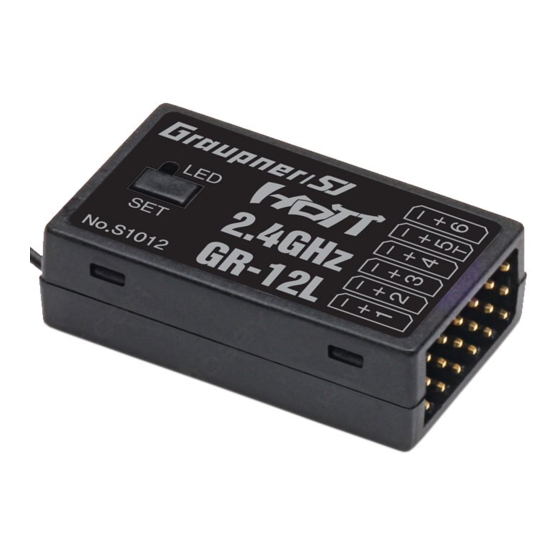
- Page 1 Manual GR-12L HoTT 6 channel 2.4 GHz HoTT receiver No. S1012...
- Page 2 2 / 20 S1012_GR-12L_DE_V1sh...
-
Page 3: Table Of Contents
Index Introduction ..................4 Service centre ...................4 Intended use ..................5 Target group ..................5 Package content ................5 Technical data ...................6 S1012 GR-12L HoTT ................6 Connection table ................6 Symbol description ................7 Safety notes ..................7 For your safety by handling the transmitter and the receiver ..8 For your safety by handling the batteries ........8... -
Page 4: Introduction
Introduction Thank you very much for purchasing a Graupner S1012 GR-12L receiver. Read this manual carefully to achieve the best results with your HoTT system and first of all to safely control your models. If you experience any trouble during operation, take the instructions to help or ask your dealer or Graupner Service Centre. -
Page 5: Intended Use
Intended use The receiver only be used for the purpose specified by the manufac- turer for operation of remote control models without passengers. Any other type of use is impermissible and may damage the system and cause significant property damage and/or personal injury. No warranty or liability is therefore offered for any improper use not covered by these provisions. -
Page 6: Technical Data
Technical data S1012 GR-12L HoTT 1 x wire 145 mm Antenna of which Antenna 30 mm Operating voltage (2.5) 3.6 ... 8.4 V Frequency range 2400 ... 2483.5 MHz Modulation 2.4 GHz FHSS Number of controls Current consumption approx. 70 mAh Temperature range -15 …... -
Page 7: Symbol Description
• Only use the components and spare parts that we recommend. Always use matching, original Graupner plug-in connections of the same design and material. • Make sure that all of the plug-in connections are tight. When dis- connecting the plug-in connections, do not pull the cables. -
Page 8: For Your Safety By Handling The Transmitter And The Receiver
For your safety by handling the transmitter and the receiver WARNING Also while programming the transmitter, make sure that a con- nected motor cannot accidentally start. Disconnect the fuel sup- ply or drive battery beforehand. CAUTION Avoid every kind of short-circuit in all sockets of the transmitter! Risk of fire! Use only the suitable connectors. -
Page 9: Installation
Connect the devices that have to be connected to the receiver to the row of sockets on one end of the receiver. The servo connections of the Graupner-HoTT receiver are numbered. The polarity of the plug-in system cannot be reversed. Do not apply force. -
Page 10: Power Supply
4.8 to 6 V. Binding To establish a connection with the transmitter, the Graupner HoTT receiver must first be "bound" to at least one model memory in "its" Graupner HoTT transmitter. This process is generally called "bind- ing". -
Page 11: Receiver Reset
If the red LED of the GR-12L HoTT lights up again constantly, the "Binding" has failed. Change the positions of the associated antennas and try the entire procedure again. Receiver reset To reset the receiver, press and hold its SET button while turning on the power to the receiver: If the reset was triggered with the transmitter switched off... -
Page 12: Setting And Display Of The Receiver Settings
DISPLAY RF STATUS of the corresponding manual as well as a detailed description of the SELECT ANNOUNCE RX DATA receiver menus on the respective product page at www.graupner. ALARM SETTING com on the Internet. Note The values shown in the following display illustrations always show the standard values. - Page 13 CH5 FUNCTION • SERVO Port "5" is suitable for operating RC components and for receiver updates. • SENSOR Port 5 is suitable for the operation of telemetry sensors. • BATT V After switching as described before, a DC voltage off max. 25,5 V can be displayed instead of the receiver voltage.
-
Page 14: Display "Mixer
With this RSSI signal and a flight control board with OSD, e.g. No. 48377, the signal strength of the receiver can be displayed in video goggles or monitors. Adjustment range: OFF, CH8, CH12, CH16 F.RESET After changing the value field to "Yes" and then pressing or tapping on the ENT key, or equivalent, a factory reset of the receiver is per- formed. -
Page 15: Display "Ch Reverse
Display "CH REVERSE" In this display, the direction of rotation of each of the servos con- CH REVERSE nected to the receiver outputs 1 ... 6 can be set individually: select CH1 : Normal CH2 : Normal the desired line; press or tap on the ENTER key or equivalent, then CH3 : Normal CH4 :... -
Page 16: Firmware Update
The programs and files required can be found in the Download area for the corresponding products at www.graupner.com Connect the adapter lead to the USB interface. The polarity of the plug-in system cannot be reversed. Note the small chamfers on the sides. - Page 17 17 / 20 S1012_GR-12L_DE_V1sh...
-
Page 18: Simplified Declaration Of Conformity
Manufaturer / Manufakturer GRAUPNER Co. Ltd Post Code: 14557 202-809, 18, Bucheon-ro 198beon-gil, Bucheon-si, Gyeonggi-do, South Korea Vertrieb Deutschland, Österreich, Niederlande D-Power Modellbau Robbe Modellsport Inhaber: Horst Derkum Geschäftsführer: Matthew White Sürther Straße 92-94 Industriestraße 10 50996 Köln 4565 Inzersdorf im Kremstal Deutschland Österreich... -
Page 19: Notes On Environmental Protection
These operating instruction are exclusively for information purposes and are subject to change without prior notification. The current version can be found on the Internet at www.graupner.com on t- th relevant product page. In addition, the company Graupner has no responsibility or liability for any errors or inaccuracies that may appear in construction or operation manuals.
Need help?
Do you have a question about the HoTT GR-12L S1012 and is the answer not in the manual?
Questions and answers