Sign In
Upload
Download
Table of Contents
Contents
Add to my manuals
Delete from my manuals
Share
URL of this page:
HTML Link:
Bookmark this page
Add
Manual will be automatically added to "My Manuals"
Print this page
×
Bookmark added
×
Added to my manuals
Manuals
Brands
GRAUPNER Manuals
Receiver
GR-12
Manual
GRAUPNER GR-12 Manual
6, 8, 12 and 16 channel 2.4 ghz hott
Hide thumbs
Also See for GR-12
:
User manual
(6 pages)
,
Manual
(12 pages)
1
2
Table Of Contents
3
4
5
6
7
8
9
10
11
12
13
14
15
16
17
18
19
20
21
22
23
24
page
of
24
Go
/
24
Contents
Table of Contents
Bookmarks
Table of Contents
Table of Contents
Introduction
Service Centre
Intended Use
Target Group
Package Content
Technical Data
Connection Table
Symbol Description
Safety Notes
For Your Safety by Handling the Transmitter and the Receiver
For Your Safety by Handling the Batteries
Installation
Connections
Power Supply
Binding
Receiver Reset
Setting and Display of the Receiver Settings
Special Features of the GR-12 Hott Receiver
Special Features of the GR-16 Hott Receiver
Special Features of the GR-24 and GR-32 Hott Receiver
Firmware Update
Simplified Declaration of Conformity
Manufacturer
Notes on Environmental Protection
Care and Maintenance
Warranty Conditions
Advertisement
Quick Links
1
Table of Contents
2
Technical Data
3
Connection Table
4
Connections
5
Power Supply
6
Binding
7
Special Features of the Gr-12 Hott Receiver
8
Special Features of the Gr-24 and Gr-32 Hott Receiver
Download this manual
Manual
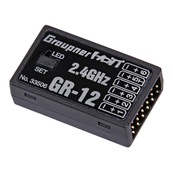
GR-12, GR-16, GR-24 and GR-32 HoTT
6, 8, 12 and 16 channel 2.4 GHz HoTT receiver
No. 33506, 33508, 33512 and 33516
Table of
Contents
Previous
Page
Next
Page
1
2
3
4
5
Advertisement
Table of Contents
Need help?
Do you have a question about the GR-12 and is the answer not in the manual?
Ask a question
Questions and answers
Related Manuals for GRAUPNER GR-12
Receiver GRAUPNER GR-12S Manual
(12 pages)
Receiver GRAUPNER 33505 User Manual
Graupner hott 2.4 system (6 pages)
Receiver GRAUPNER GR-16 HoTT Manual
2.4 ghz 8 channel receiver (16 pages)
Receiver GRAUPNER HOTT GR-32 Manual
(12 pages)
Receiver GRAUPNER 33516 Manual
Receiver hott 2.4 (11 pages)
Receiver GRAUPNER GR-12L Manual
Hott 2.4ghz sumd+t diversity receiver (24 pages)
Receiver GRAUPNER GR-12L Manual
6 channel 2.4 ghz hott receiver (20 pages)
Receiver GRAUPNER HoTT GR-18 User Manual
Receiver with copterfirmware (16 pages)
Receiver GRAUPNER GR-18 Manual
3xg+3a+vario, 3xg+3a+3m+vario (39 pages)
Receiver GRAUPNER GR-18 Manual
3xg+3a+vario. 3xg+3a+3m+vario (80 pages)
Receiver GRAUPNER Falcon 12 Manual
2,4 ghz hott receiver with 3-axis gyro (and vario) (52 pages)
Receiver GRAUPNER GR-18 Series Manual
Hott receiver with firmware for racecopter, copter without gps supported mode, 3d copter (24 pages)
Receiver GRAUPNER GR-16L Operating Instructions Manual
(16 pages)
Receiver GRAUPNER GR-12SC+ Manual
6 channel 2.4 ghz hott receiver (11 pages)
Receiver GRAUPNER GR-12SH+ Manual
(12 pages)
Receiver GRAUPNER HOTT GR-12SH+ Manual
(9 pages)
This manual is also suitable for:
Gr-16
Gr-24
Gr-32
33506
33508
33512
...
Show all
33516
Table of Contents
Print
Rename the bookmark
Delete bookmark?
Delete from my manuals?
Login
Sign In
OR
Sign in with Facebook
Sign in with Google
Upload manual
Upload from disk
Upload from URL


Need help?
Do you have a question about the GR-12 and is the answer not in the manual?
Questions and answers