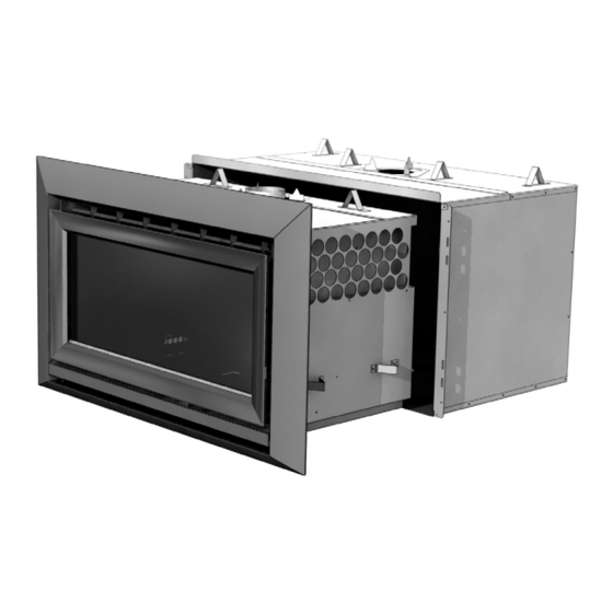
Escea IB850 Service Manual
Hide thumbs
Also See for IB850:
- Installation manual (23 pages) ,
- Quick start manual (2 pages) ,
- User manual (19 pages)
Advertisement
Table of Contents
IB850 and IB600
Service Manual
AUSTRALIAN EDITION
Important
• This appliance should be serviced every 12 to 24 months
• Any service operation should be carried out only by a suitably qualified and trained person
• Gas and electricity supply MUST be isolated before any service operation is carried out
on this appliance.
• This manual must be left with the appliance.
Manufactured by: Escea Ltd, PO Box 5277 Dunedin NZ, Ph: 03 479 0302, e:
Distributed by: Glen Dimplex, Unit 2 205 Abbotts Road, Dandenong, Melbourne. Ph: +61 3 87873567
G8872_1 Service Manual AUS
info@escea.co.nz
Advertisement
Table of Contents

Subscribe to Our Youtube Channel
Summary of Contents for Escea IB850
- Page 1 • This manual must be left with the appliance. Manufactured by: Escea Ltd, PO Box 5277 Dunedin NZ, Ph: 03 479 0302, e: info@escea.co.nz Distributed by: Glen Dimplex, Unit 2 205 Abbotts Road, Dandenong, Melbourne. Ph: +61 3 87873567...
-
Page 2: Table Of Contents
Contents: Page: Error Codes Cleaning the Log Set and Glass Checking Operating Pressure Removing / Cleaning Fan Removing Electronic Draw Replacing a Wireless Control Gas Type Conversion Annual Service Procedure Wiring Diagram G8872_1 Installation Manual AUS... -
Page 3: Error Codes
IB850 - Usually insufficient cavity ventilation. Note: This error has a PCB Over Temp permanent lock out and will require the unit to be reset 10 minutes after (Printed Circuit Board) the initial error (turning the power to the fire off "at the wall"... - Page 4 This indicates a fault with one of the two temperature sensors installed in your fire. Resetting the fire (turning the power to the fire off then on again after a few seconds) and if the fault reappears, please contact your Escea sales agent to organise a replacement sensor.
-
Page 5: Cleaning The Log Set And Glass
The outside of the fascias must only be cleaned with a damp cloth. The high temp silver powder coating that is used on Escea fascia parts contains certain amounts of aluminium that when rubbed too hard will oxidise leaving a big black smudge that cannot be removed. -
Page 6: Checking Operating Pressure
5) Replace operating test point screw and leak test both test points. A = Operating Pressure test point B = Pressure adjustment screw C = Inlet pressure test point D = Inlet gas connection IB850 and IB600 Pressure Table Gas Type Minimum Inlet Pressure 2.5KPa 1.2KPa Maximum Inlet Pressure 3.5KPa... -
Page 7: Removing / Cleaning Fan
Removing or Cleaning Fan As part of regular service procedure, it is recommended that the fan is removed for cleaning. Dust will build up on the fan rotor and in the cavity where the fan is located. This can be removed by the service person using a vacuum cleaner. -
Page 8: Removing Electronic Draw
All of the electronic components of the heater have been located on a removable draw. This draw is located on the left hand outer side of the IB850 and under the front burner of the IB600. On the back of the draw are two large connectors that unplug as the draw is removed so only the three wires connecting the electronics to the igniters and flame rod must be removed manually from the PCB (Printed Circuit Board). -
Page 9: Replacing A Wireless Control
During this time the fire will re-ignite. NOTE: During this period the fire will listen for any coded remote signal and re-address itself to this new code. So make sure the batteries of any other Escea remote that may be nearby are removed. -
Page 10: Gas Type Conversion
Gas Type Conversion Procedure: Step one: Remove inner fascia, glass and logs (as described earlier in this manual). Service person may also wish to remove the firebox to increase the work space within the heater. Step two: Take out front two burners by removing the screws from Step 2 either end of the burner top... -
Page 11: Annual Service Procedure
Annual service procedure: 1. Isolate power to fire. 2. Remove front glass and clean inside of glass. 3. Remove logs and brush off any soot. 4. Remove burners and blow compressed air through them. 5. Remove jets and clean injector hole with solvent. 6. -
Page 12: Wiring Diagram
Wiring Diagram: G8872_1 Installation Manual AUS...


Need help?
Do you have a question about the IB850 and is the answer not in the manual?
Questions and answers