Escea ST900 Installation Manual
Direct vent gas fireplace
Hide thumbs
Also See for ST900:
- Installation manual (49 pages) ,
- User manual (18 pages) ,
- Manual (9 pages)
Table of Contents
Advertisement
Quick Links
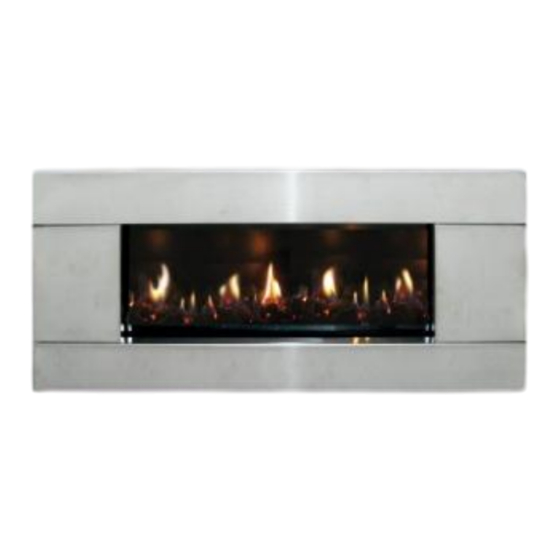
ST900 Direct Vent Gas Fireplace
Installation Manual
NEW ZEALAND EDITION
Important:
The appliance shall be installed in accordance with;
• This installation instruction booklet
• Local gas fitting regulations
• Municipal building codes
• Electrical wiring regulations
• NZS 5261, Gas installations
• Any other relevant statutory regulations.
• Must be installed by a qualified person
Manufactured by: Escea Ltd, PO Box 5277 Dunedin NZ, Ph: 03 479 0302, e: info@escea.co.nz
630156_5_Manual_Installation-Service_ST900_NZ_R-emotion
Advertisement
Table of Contents

Subscribe to Our Youtube Channel
Related Manuals for Escea ST900


Summary of Contents for Escea ST900
- Page 1 • Municipal building codes • Electrical wiring regulations • NZS 5261, Gas installations • Any other relevant statutory regulations. • Must be installed by a qualified person Manufactured by: Escea Ltd, PO Box 5277 Dunedin NZ, Ph: 03 479 0302, e: info@escea.co.nz...
- Page 2 • Gas pipe placement to the front left of the cavity. • The ST900 electronic control system is designed to work within the temperature range of 0°C to 60°C, with a humidity level that is non condensing. This is to ensure safe operation of the electronic and gas control system.
- Page 3 630156_5_Manual_Installation-Service_ST900_NZ_R-emotion Recommended Installation Process: The following diagram illustrates the steps required to install your gas fire, and the trades required at each stage. The sequence in which you choose to do these tasks will vary depending on your individual scenario. Please read these instructions fully before proceeding with the installation. Leave the installation of the fascia panels until the very end of the installation and commissioning to avoid damage to the fascia panels.
-
Page 4: Table Of Contents
630156_5_Manual_Installation-Service_ST900_NZ_R-emotion Contents: Product Description Creating the Cavity Hearth and Floor Clearances Wall Linings Vertical Clearances Corner Installations Laying Gas Pipe Connecting Gas Pipe Power Supply 10.0 Fixing Fire to Wall 11.0 Removing the Firebox Glass 12.0 Installing the Flue system 13.0 Fitting the Flue Restrictor 14.0... -
Page 5: Product Description
The cavity specifications vary depending on fascia type. The dimensioned drawings below show the size of opening that must be created to fit the ST900. The wall directly above the fire should be finished / gibbed / lined after the fire has been installed, unless there is an access hatch or the chase is open to the ceiling cavity, which allows the flue to be installed after the wall has been lined. -
Page 6: Hearth And Floor Clearances
Hearth and Floor Clearances: There should be at least 100mm between the bottom of the ST900 fire and any horizontal surface below, for example hearths and floors. Wall and Cabinet Clearances: There must be a minimum of 100mm from the sides of the fascia to any protruding side walls or cabinetry. -
Page 7: Wall Linings
The drawings below are suggestions that may be used as a GUIDE for those consumers who do decide to locate their TV above an ST900 gas fire. These drawings show ways to reduce the amount of warm air rising off the fireplace and onto the TV. -
Page 8: Corner Installations
ST900. Note: Escea does not recommend placement of items on the mantles shown in the diagram to the right. This is because of the potential for items placed on or above the mantle to be affected by the heat rising from the appliance. -
Page 9: Connecting Gas Pipe
Soft copper should be run directly to fire and connected onto the regulator with flare nut (3/8” BSP thread). The regulator that is supplied with the fire MUST NOT BE REMOVED. Removal of the regulator, or replacing it with one not intended for use with an Escea fire, will void the limited appliance warranty. -
Page 10: Removing The Firebox Glass
As the ST900 draws a small current when not in use, it is recommended to remove the batteries if the fire will not be in use for long periods of time. -
Page 11: Installing The Flue System
630156_5_Manual_Installation-Service_ST900_NZ_R-emotion 12.0 Installing the Flue System: Ensure all flue components are Simpson Duravent Direct Vent Pro 5” x 8,” no other flue types may be used. Note: Consult section 12.13 to ensure correct length of flue is calculated. There are two basic types of Balanced Flue System installations: •... - Page 12 630156_5_Manual_Installation-Service_ST900_NZ_R-emotion 12.5 Vertical Only Flue Diagram: Use this diagram to determine what percentage of flue restriction in required to ensure safe and correct operation of the ST900 decorative gas fireplace.
- Page 13 630156_5_Manual_Installation-Service_ST900_NZ_R-emotion 12.6 Horizontally Terminating Flue Diagram: Use this diagram to determine what percentage of flue restriction in required to ensure safe and correct operation of the ST900 decorative gas fireplace.
- Page 14 630156_5_Manual_Installation-Service_ST900_NZ_R-emotion 12.7 Vertically Terminating flue with a Horizontal Offset: Use this diagram to determine what percentage of flue restriction in required to ensure safe and correct operation of the ST900 decorative gas fireplace.
- Page 15 630156_5_Manual_Installation-Service_ST900_NZ_R-emotion 12.8 Standard Flueing Configurations: The following flue components are available from escea in kitset form. DVF-H DVF-V...
- Page 16 630156_5_Manual_Installation-Service_ST900_NZ_R-emotion 12.9 Locating the Flue Terminal: The flue terminal must be located using the information given in the following diagram and table based on NZS 5261...
- Page 17 630156_5_Manual_Installation-Service_ST900_NZ_R-emotion Table 16 – Minimum clearances required for flue terminals shown in figure 3 Ref. Item Minimum Clearances (mm) Natural draught assisted Below eaves, balconies and other projections: Gas appliances up to 50 MJ/h input Gas appliances over 50 MJ/h input From the ground, above a balcony or other surface (see note 6) From a return wall or external corner (see note 6) From a gas meter (M) (see 2.5.4.9 for vent terminal location of...
- Page 18 630156_5_Manual_Installation-Service_ST900_NZ_R-emotion 12.11 Sealing ‘through roof’ and ‘through wall’ penetrations: For „through roof‟ penetrations, use a Deck-tite flashing or equivalent to create a weather- tight seal between the flue and the roof cladding. For „through wall‟ penetrations, this will require the use of a Wall Thimble. The Wall Thimble will ensure you have suitable clearance from combustibles as well as sealing the penetration.
- Page 19 630156_5_Manual_Installation-Service_ST900_NZ_R-emotion 12.13 Points to note when planning the Installation of the Escea DV flue: This flue system cannot be cut to length. Correct lengths must be selected for each installation. For a full list of available flue lengths, contact your Escea retailer.
-
Page 20: Fitting The Flue Restrictor
630156_5_Manual_Installation-Service_ST900_NZ_R-emotion 13.0 Fitting the Flue Restrictor: If your flueing configuration requires that you fit a flue restrictor (see graph in section 12.5, 12.6 & 12.7 of this manual to find out if your configuration requires a flue restrictor), follow the instructions below. -
Page 21: Converting To Natural Gas
630156_5_Manual_Installation-Service_ST900_NZ_R-emotion 14.0 Converting to Natural Gas: Where a conversion to natural gas is needed, the following steps should be followed 14.1 First you need to remove the burner by removing the screw holding it in place on the left hand side of the firebox (Fig. 1). Then remove the 1.3mm burner jet (Fig. - Page 22 630156_5_Manual_Installation-Service_ST900_NZ_R-emotion Finally, put the sticker supplied in the conversion kit in onto the dataplate of the ST900 in the position shown. The sticker must be signed and dated by the installer who has converted the fire.
-
Page 23: Placing The Fuel Bed
630156_5_Manual_Installation-Service_ST900_NZ_R-emotion 15.0 Placing the Fuel Bed Media: Your ST900 Gas fire will be supplied with a Fuel Bed kit. Follow the instructions below for the Fuel Bed kit that applies to you. 15.1 Driftwood Fuel Bed: First scatter one layer of the supplied white stones evenly across the base of the firebox, ensuring there are no stones or driftwood pieces inside the pilot flame surround guard. - Page 24 630156_5_Manual_Installation-Service_ST900_NZ_R-emotion WARNING: The regulator that is supplied with the fire MUST NOT BE REMOVED. Removal of the regulator, or replacing it with one not intended for use with an Escea fire, will void the limited appliance warranty. The regulator is factory set (not adjustable) to supply the correct operating pressures based on the minimum and maximum inlet pressure in the table below for the relevant gas type.
-
Page 25: Covering Up The Fire
630156_5_Manual_Installation-Service_ST900_NZ_R-emotion 17.0 Covering up the fire: Before the wall surrounding the ST900 is lined, the fire must be covered up and sealed to prevent Gib dust from getting into the fire. It is recommended that the packaging supplied with the fire is used to achieve this. - Page 26 The perforated surface (grill) should be on top. The ST900 fascia uses these four hooks for attaching to the fire. Do this by lining up the fascia hooks with the receptacles on the sides of the fire.
- Page 27 Install the lower fascia magnet brackets using the 4x supplied screws in the two positions shown below. (Do not affix the magnets at this stage) Installation: The ST900 fascia uses the hooks on the rear for attaching to the fire. Line up the hooks with the receptacles on the sides of the fireplace, and lift the fascia so that the hooks are above the receptacles.
- Page 28 Place lower trim by securing it to the magnet brackets attached in step 3. 18.4 Cleaning the ST900 Fascia: The fascia must be cold before starting any form of maintenance or cleaning. If your Stainless Steel fascia requires cleaning, 3M Stainless Steel cleaner (or equivalent) is recommended.
-
Page 29: Operating Instructions
19.3 Switching on the ST900: Note: If this is the first time running the ST900 the air will need to be purged from the gas lines. To do this, follow the instructions below to switch the fire on and then switch it off. - Page 30 630156_5_Manual_Installation-Service_ST900_NZ_R-emotion 19.4 Switching off the ST900: To turn off the fire, push the OFF button, to shut down the gas flow to the fire and switch it off. The OFF display will now appear in the display. 19.5 Setting the control mode for the fireplace: There are three different modes for controlling the appliance: >...
- Page 31 630156_5_Manual_Installation-Service_ST900_NZ_R-emotion > Program mode: By default the program mode is not enabled. To enable program mode, enter configuration mode by pressing and holding the OFF button for 40 seconds, selecting “Programming” and selecting “yes” (For more information on configuration mode see section 19.9). There are two types of program mode: a Daily mode and a Weekly mode.
- Page 32 Similarly, if „Flame Down‟ is pressed while the unit is in the „pilot‟ flame position, nothing will happen. To shut down the gas flow to the ST900, press the On/Off button and the LED will begin to blink and the unit will emit a beep.
- Page 33 630156_5_Manual_Installation-Service_ST900_NZ_R-emotion 19.10 Pairing the Remote to the Control Unit: Install batteries to the battery pack and after a while the valve motor will start moving (if not wait one minute from the time of installing batteries). Once the valve has finished moving, press the OFF button on the remote control for 40 seconds.
- Page 34 630156_5_Manual_Installation-Service_ST900_NZ_R-emotion 19.11 Initial configuration: To enter the configuration menu, press the OFF button on the remote control for 40 seconds. During this time the screen may go blank, this is normal. After 40 seconds, the configuration menu appears. It is possible to configure the appliance with the following options: ...
-
Page 35: Sounds And Smells
630156_5_Manual_Installation-Service_ST900_NZ_R-emotion 20.0 Sounds And Smells: Note: Each time the fire is lit from cold the glass will fog up with condensation. This is normal and the condensation will disappear within a few minutes once the glass heats up. 20.1 Sounds: It is possible that you will hear some sounds from your gas appliance. -
Page 36: Annual Service Check
630156_5_Manual_Installation-Service_ST900_NZ_R-emotion 21.0 Annual Service Check: The ST900 Fireplace should be serviced annually to ensure it continues to operate in a safe manner. This annual service check should involve the following Replace thermocouple Check glass assembly gasket Clean pilot and main burner jets ... -
Page 37: Warranty Terms And Conditions
ESCEA operating and maintenance instructions, then for the first period of twelve (12) months from the date of purchase ESCEA will pay the cost of repairing or replacing any part of the Product that is deemed by ESCEA to be faulty.
Need help?
Do you have a question about the ST900 and is the answer not in the manual?
Questions and answers