Escea IB850 Installation Manual
Ib850; ib600 indoor fireplace
Hide thumbs
Also See for IB850:
- Service manual (12 pages) ,
- Installation manual (6 pages) ,
- Quick start manual (2 pages)
Advertisement
Quick Links
IB850 and IB600
Installation Manual
AUSTRALIAN EDITION
Important:
The appliance shall be installed in accordance with;
• This installation instruction booklet
• Local gas fitting regulations
• Municipal building codes
• Electrical wiring regulations
• AS 5601, Gas installations
• Any other relevant statutory regulations.
• Must be installed by a qualified person
• Must be installed with an Outer Skin Kit (Separate Kit)
This appliance is not intended for use by young children or infirm persons unless they have been
adequately supervised by a responsible person to ensure that they can use the appliance safely.
Young children should be supervised to ensure that they do not play with the appliance.
Manufactured by: Escea Ltd, PO Box 5277 Dunedin NZ, Ph: 03 479 0302, e:
Distributed by: Glen Dimplex, Unit 2, 205 Abbotts Road, Dandenong, Melbourne. Ph: +61 3 87873567
G8860_2 Installation Manual AUS
info@escea.co.nz
Advertisement

Subscribe to Our Youtube Channel
Related Manuals for Escea IB850


Summary of Contents for Escea IB850
- Page 1 Young children should be supervised to ensure that they do not play with the appliance. Manufactured by: Escea Ltd, PO Box 5277 Dunedin NZ, Ph: 03 479 0302, e: info@escea.co.nz Distributed by: Glen Dimplex, Unit 2, 205 Abbotts Road, Dandenong, Melbourne.
- Page 2 Warranty Repair and Annual Servicing: Warranty repair work must be carried out by a recognised Escea gas fire technician. It is recommended that recognised Escea Gas fire technicians are also used to carry out annual servicing requirements (particularly during the warranty period).
-
Page 3: Table Of Contents
Contents: Section: • Product Description • Creating the Outer Skin Kit Cavity • Hearth____________ • Raising the fire up a wall_ • Wall Linings • Mantle Clearance • Television Clearance • Corner Installations • Power Supply • Installing the Flue System •... -
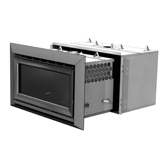
Page 4: Product Description
Product Description: The Escea IB850 and IB600 gas fires are designed to be built into a cavity. Both appliances are flued conventionally via a Ø100mm flue system. The user will control their fire with the Radio Frequency (RF) remote that will normally be left in its wall mount cradle. -
Page 5: Hearth
The following are the recommended minimum clearances for the location of any electrical equipment (such as Plasma TV, LCD TV or home theatre) above an Escea IB Series gas fire. Use either a shelf mantle below your TV screen or alternatively you can construct a recess to mount your TV screen into. -
Page 6: Corner Installations
Corner Installations: If a cavity is to be created in a corner, the following drawings give the minimum sized interior wall and resultant flue position. IB 600 minimum corner install dimensions: 398mm 915mm 710mm 45° 398mm MAINTAIN CLEARANCES 492mm 1830mm 1043mm 560mm 960mm... -
Page 7: Power Supply
Power Supply: Locating the plug within the cavity makes the installation very neat but the provision must be made to be able to switch the power supply off and on (electrical isolation switch) and must be accessible after the heater has been installed. This is normally done by means of a separate switch located outside of the cavity and wired to the plug. -
Page 8: Installing The Flue System
The flue and liner must be supported The top of the flue must be capped with an appropriate and approved anti down draft cowl. All the required flue components are available from your Escea dealer in both kitset form and as individual components. -
Page 9: Laying Gas Pipe
The top of the flue must be capped with an appropriate and approved anti down draft cowl. Note: Chimney liner flue kits intended for other brands of heater may not fit. Escea flue spigot is 100mm inside diameter. - Page 10 10.2 The Outer Skin Kit has 4 possible entry points for solid gas pipe, on the four corners of the kit. Each is sealed by a ‘knock-out’. Remove only the knock-out which you require, and place the supplied rubber plug into the hole. You will need to make a small cut into the rubber plug to allow the gas pipe to pass through, keeping the plug as air-tight as possible.
- Page 11 11.2 Attach the Rear to the Sides and Base: The rear panel fits inside the Side and Base panels, make sure the flanges on the Side and Base panels are on the outside. The two holes on the Rear panel go towards the bottom. 11.3 Attach the Top-Rear: Attach the top-rear panel to the Sides and Rear...
-
Page 12: Fix The Outer Skin Kit (Osk) Into The Cavity
12.0 Fix the Outer Skin Kit (OSK) into the cavity: Slide the OSK into the cavity, ensuring the gas pipe passes through the grommet at the back of the OSK and is within 100mm of the front right hand corner. Secure the OSK to the wall using screws or other fasteners through the slots at the front of the Side panels. -
Page 13: Removing The Front Glass
15.0 Removing the front glass: Step 1: Unscrew the top glass retainer and remove it. Take care that the glass does not fall forwards at this stage Step 2: Lift out glass and place it carefully aside. 16.0 Connecting Flue to Heater: This is a 7 step process and is performed after the heater has been pushed into position in the cavity and before fascia panels have been fitted. - Page 14 4) For best access we recommend removing the fire box. Undo the four screws on the front four corners of the fire box (as shown below) and pull the fire box out of the heater. It should now be possible to reach up from inside of the heater and connect the flue to the heater’s flue spigot.
-
Page 15: Connecting The Gas Pipe
(BSP thread). The regulator that is supplied with the fire MUST NOT BE REMOVED. Removal of the regulator, or replacing it with one not intended for use with an Escea fire, will void the limited appliance warranty. -
Page 16: Fixing The Heater To The Base And Wall
18.0 Fixing the Heater to the base and wall: There are several ways that the heater can be fixed against movement: It is a requirement that this heater be securely fastened to the wall and base. Note: It is important that the outer fascia is used during this process to ensure that the heater is located in the appropriate position within the cavity. -
Page 17: Locating The Log Set
2) Place rear log (long rectangular one) into position by inserting it in behind retainer bracket. 3) IB850 only: Place the other smaller piece of rear log into the RH rear side of fire box behind its retainer bracket. 4) Place front three log sets into position on the log retaining brackets, over the top of the main burners. -
Page 18: Electrode Placement
19.1 Log Replacement: The fire unit should never be used with broken logs. Turn off the fire and allow the unit to cool before removing the glass to carefully remove the logs. If for any reason a log should need replacement, you must use the proper replacement log. -
Page 19: Checking Operating Pressure
Checking Operating Pressure: WARNING: The regulator that is supplied with the fire MUST NOT BE REMOVED. Removal of the regulator, or replacing it with one not intended for use with an Escea fire, will void the limited appliance warranty. This is done at the regulator located at the front RH corner of the appliance. -
Page 20: Fitting The Fascia Panels
Bracket. Note: If the glass gasket requires a replacement, call your nearest Escea agent who will ensure the part is replaced with the correct type. In the event that the glass is broken by impact, purchase the replacement from an authorised Escea agent only. -
Page 21: Locating Wall Mount Cradle For Wireless Control
5. A suitable distance away from the heater. 6. Ideally 1.2m to 1.5m from the floor The radio frequency signal will go through some walls but for best results Escea suggest that the cradle position is between 5 and 15 meters away from the heater. -
Page 22: Normal Operating Sounds And Smells
Fan: Escea Gas appliances use electric fans to push heated air further into the room. It is not unusual for the fan to make a “whirring” sound when ON. This sound will increase or decrease in volume depending on the speed setting of your fan. -
Page 23: Installation Check List
25.0 Installation Check List: Tick here Ensure there is adequate ventilation in the masonry cavity.__ Ensure the spark electrodes are correctly positioned. Operating pressure checked with heater running on full (all burners operating) and all other gas appliances in the house switched on.
Need help?
Do you have a question about the IB850 and is the answer not in the manual?
Questions and answers