
Related Manuals for BIG ASS FANS Essence


Summary of Contents for BIG ASS FANS Essence
- Page 1 INSTALLATION GUIDE Essence ® For help, call 1-877-BIG-FANS or visit www.bigassfans.com...
- Page 2 ESSENCE ® Installation Checklist Did a structural engineer approve the mounting structure? See page 7 for Big Ass Fans-approved mounting structures. Are you familiar with the function and use of the safety cable? See pages 21–22 for information on properly securing the safety cable.
-
Page 3: Contact Information
Essence and the Essence logo are trademarks of Delta T Corporation. All other trademarks used herein are the properties of their respective owners. No part of this document may be reproduced or translated into a different language without the prior written consent of Big Ass Fan Company. The information contained in this document is subject to change without notice. For the most up-to-date information, see the online Essence Installation Guide at www.bigassfans.com. -
Page 4: Important Safety Instructions
ESSENCE ® IMPORTANT SAFETY INSTRUCTIONS READ AND SAVE THESE INSTRUCTIONS TO REDUCE THE RISK OF FIRE, ELECTRIC SHOCK, OR INJURY TO PERSONS, OBSERVE THE FOLLOWING: CAUTION: Installation work and electrical wiring must be done by qualified person(s) in accordance with all applicable codes and standards. -
Page 7: Table Of Contents
ESSENCE ® Contents General Information Important Safety Information Reference Guide Reference Guide: Mounting Introduction Thank You About Big Ass Fans About this Fan Pre-Installation What’s in the Box Parts Included Tools Needed Alternative Mounting Methods Fan Diagram Preparing the Work Site Mounting Structure: 1. - Page 8 ESSENCE ® Contents Wiring the Fan (cont.) Wiring the Fan (Wired Wall Controller) Wiring the Fan (Wireless Wall Controller) Wiring: Fire Signal Relay Wiring: 0–10VDC Automation Wired Wall Controller Dimensions Mounting to a Junction Box Installation Mounting Directly to a Wall...
-
Page 9: About This Fan
110–125 VAC motor or a 200–240 VAC motor. The fan’s voltage is marked on the fan packaging and ® on the label on top of the main fan unit. The voltage cannot be changed during installation. Ensure your fan is the correct voltage prior to beginning installation. 110–125 VAC Essence Minimum required Rated Fan diameter... -
Page 10: What's In The Box
9. Optional. The L-Bracket Mounting Kit is included only if ordered and is packaged in the main box. 10. Winglets are standard on Essence fans; however, airfoil tips are available as on option. Winglets or airfoil tips are installed on the airfoils during airfoil installation. -
Page 11: Parts Included
ESSENCE ® Pre-Installation (cont.) Parts included Mounting methods vary by mounting structure. See the appropriate Mounting Structure section for specialized installation instructions. Note: Drawings below are not to scale. Hardware Mounting Hardware Extension Tube Hardware Safety Cable Hardware Main Fan Unit Hardware... -
Page 12: Tools Needed
ESSENCE ® Pre-Installation (cont.) Parts included (cont.) Note: Drawings below are not to scale. Electrical Airfoils (8) Airfoil Wired Wall Controller OR Wireless Wall Controller (optional) (8) Winglet (8) Airfoil Tip (8) Airfoil Retainer Cover Plate Assembly Power Supply Cable 1. -
Page 13: Alternative Mounting Methods
Z-Purlin Brackets Specialized brackets can be purchased for hanging the Essence from building structures consisting of Z-purlins with lengths ≤30 ft (9.1 m) and heights ranging from 8” (20.3 cm) to 10” (25.4 cm), and spaced ≤5 ft (1.5 m) apart. The Z-purlin brackets accommodate up to a 5:12 roof pitch. -
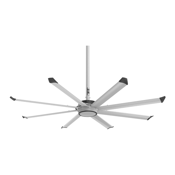
Page 14: Fan Diagram
E. Main fan unit. Includes the motor, hub, and power wiring. F. Airfoil. Provides air movement. The unique, patented design provides efficient and effective air movement. G. Winglet. Improves the efficiency of the fan. Winglets are standard on Essence fans; however, airfoil tips are available as on option. -
Page 15: Preparing The Work Site
• Ensure power wiring is routed to a junction box at the fan location prior to installation. • Essence is shipped with either a 110–125 VAC motor or a 200–240 VAC motor. The fan’s voltage is marked on the fan packaging ®... -
Page 16: Select Proper Angle Irons
ESSENCE ® Mounting Structure: Bar Joists WARNING: The fan can weigh up to 120 lbs (54.4 kg). The fan should not be installed unless the structure on which the fan is to be mounted is of sound construction, undamaged, and capable of supporting the loads of the fan and its method of attachment. -
Page 17: Pre-Drill Angle Irons
ESSENCE ® Mounting Structure: Bar Joists (cont.) 2. Pre-drill angle irons Drill two Ø 7/16” (1.1 cm) holes exactly 5-1/2” (14 cm) apart in the centers of two angle irons. Measure the distance between the mounting points of the roof structure that the angle irons will span. Measure the same distance on the angle irons, and drill Ø... -
Page 18: 4A. Fasten Single Angle Irons To Roof Structure Mounting Points
ESSENCE ® Mounting Structure: Bar Joists (cont.) 4a. Fasten single angle irons to roof structure mounting points If installation requires double angle irons, i.e., span is greater than 8 ft (2.4 m), proceed to step 4b. CAUTION: The angle irons must be fastened to the roof structure at each end. -
Page 19: 4B. Fasten Double Angle Irons To Roof Structure Mounting Points
ESSENCE ® Mounting Structure: Bar Joists (cont.) 4b. Fasten double angle irons to roof structure mounting points CAUTION: The angle irons must be fastened to the roof structure at each end. Fasten the angle irons to the roof structure mounting points at each end with customer-supplied Grade 8 hardware as shown. Do not tighten the hardware until the fan has been mounted to the angle irons. -
Page 20: Identify Mounting Location
ESSENCE ® Mounting Structure: Wood Frame Wood framing channels are mainly used in residential homes. Consult a structural engineer to ensure you have selected the correct mounting method for your building structure. WARNING: The fan can weigh up to 120 lbs (54.4 kg). The fan should not be installed unless the structure on which the fan is to be mounted is of sound construction, undamaged, and capable of supporting the loads of the fan and its method of attachment. -
Page 21: 2B. Fasten Brackets (To Floor Joists)
ESSENCE ® Mounting Structure: Wood Frame (cont.) 2b. Fasten brackets (to floor joists) Note: This method should be used when the tops of the joists are inaccessible. Fasten the brackets to the mounting points on the floor joists using the Wood Frame Mounting Hardware as shown. Torque to 25 ft·lb (33.9 N·m). -
Page 22: Pre-Drill Suitable Mounting Beam
ESSENCE ® Mounting Structure: Solid Beam L-brackets are used used to mount the fan to a solid beam. Consult a structural engineer to ensure you have selected the correct mounting method for your building structure. WARNING: The fan can weigh up to 120 lbs (54.4 kg). The fan should not be installed unless the structure on which the fan is to be mounted is of sound construction, undamaged, and capable of supporting the loads of the fan and its method of attachment. -
Page 23: 3A. Attach L-Brackets (To Mounting Structure)
ESSENCE ® Mounting Structure: Solid Beam (cont.) 3a. Attach L-brackets (to mounting structure) Fasten the L-brackets to the mounting structure using the customer-supplied 1/2-13 or M12 L-Bracket Hardware as shown below. Note: L-bracket orientation may differ from the illustration. Proceed to "Hanging the Fan" on the following page. -
Page 24: Route Wiring And Safety Cable Into Extension Tube
ESSENCE ® Hanging the Fan 1. Route wiring and safety cable into extension tube Controller Input Power Supply Note: To facilitate installation, Big Ass Fans recommends that the extension Cable Cable tube is horizontal with the rectangular access hole facing up during this step. -
Page 25: 3A. Attach Upper Mount (To Angle Irons)
ESSENCE ® Hanging the Fan (cont.) 3a. Attach upper mount (to angle irons) Secure the upper mount (with extension tube and upper mounting brace already attached) directly to the angle irons using the Mounting Hardware as shown. Consult the diagrams below for distances between the angle irons. Tighten the hardware so that it is snug, but do not torque. -
Page 26: 3B. Attach Upper Mount (To Wood Framing Channels)
ESSENCE ® Hanging the Fan (cont.) 3b. Attach upper mount (to wood framing channels) When cutting the wood framing channels, be sure the holes on each end will line up with the holes on the mounting brackets! Secure the upper mount (with extension tube and upper mounting brace already attached) to the wood framing channels using the Mounting Hardware as shown. -
Page 27: Fasten Wood Framing Channels (To Brackets, Wood Frame Mounting Only)
ESSENCE ® Hanging the Fan (cont.) 4. Fasten wood framing channels (to brackets, wood frame mounting only) The center-to-center distance between the two beams or joists between which the fan will hang cannot be greater than 24 in (61 cm). If mounting to bar joists or a solid beam, proceed to step 5. -
Page 28: Secure Safety Cable (To Main Fan Unit)
ESSENCE ® Hanging the Fan (cont.) 5. Secure safety cable (to main fan unit) CAUTION: Do not remove the main fan unit from its protective packaging or place it on a flat surface prior to hanging it! CAUTION: To prevent damage, avoid contact with the stator wires located on the bottom of the main fan unit! CAUTION: The main fan unit is heavy. -
Page 29: Tighten Hardware
ESSENCE ® Hanging the Fan (cont.) 7. Tighten hardware After attaching the main fan unit to the extension tube, tighten the following hardware to the specified torque. • Tighten the Mounting Hardware to 25 ft·lb (33.9 N·m) using a 17 mm wrench and a torque wrench with a 17 mm socket. -
Page 30: 8C. Secure Safety Cable (To Solid Beam)
ESSENCE ® Hanging the Fan (cont.) 8c. Secure safety cable (to solid beam) WARNING: The safety cable is a crucial part of the fan and must be installed correctly. If you have any questions, call Customer Service. Secure the safety cable to the mounting structure by wrapping it around the structure and securing the loose end with the Gripple as shown. -
Page 31: Install Cover Plate Assembly
ESSENCE ® Hanging the Fan (cont.) 10. Install cover plate assembly Plug the remaining male wiring harness from the fan into the female wiring harness on the cover plate assembly as shown. Ensure all wiring is tucked inside the extension tube, and then attach... -
Page 32: Attach Guy Wire Clamps
ESSENCE ® Installing Guy Wires Guy wires may not be included in your fan order. They are intended to restrain the fan’s lateral movement and are only included in fan orders that have extension tubes 4 ft (1.2 m) or longer. Depending on the operational environment (wind, mounting structure, etc.), guy wires may be needed regardless of extension tube length. -
Page 33: Attach Locking Carabiners To Guy Wire Clamps
ESSENCE ® Installing Guy Wires (cont.) 2. Attach locking carabiners to guy wire clamps Secure the four (4) locking carabiners to the guy wire clamps as shown. Securely tighten the carabiners. 3a. Attach beam clamp (bar joist mounting) The guy wire should be at a 45° angle from the extension tube (see the illustrations on the following page). -
Page 34: Route Guy Wire Through Gripple
ESSENCE ® Installing Guy Wires (cont.) 4. Route guy wire through Gripple ® Route the guy wire through the Gripple and the carabiner on the guy wire clamp, and then back through the Gripple as shown below. ® Do not tighten the Gripple until the remaining guy wires have been installed. -
Page 35: Attach Winglets Or Airfoil Tips (To Airfoils)
Big Ass Fans recommends wiring the fan (page 29) before installing the airfoils. WARNING: Disconnect power to the fan before installing the airfoils. 1. Attach winglets or airfoil tips (to airfoils) Note: Winglets are standard on Essence fans; however, airfoil tips are available as an option. ®... -
Page 36: Attach Airfoils (To Main Fan Unit)
ESSENCE ® Installing Airfoils (cont.) 3. Attach airfoils (to main fan unit) WARNING: Disconnect power to the fan before installing airfoils. Attach the eight (8) airfoil retainers using the Airfoil Hardware. Moving clockwise around the fan hub, position the airfoil retainers as shown. -
Page 37: Power Requirements
110–125 VAC motor or a 200–240 VAC motor. The fan’s voltage is marked on the fan packaging and ® on the label on top of the main fan unit. The voltage cannot be changed during installation. Ensure your fan is the correct voltage prior to beginning installation. 110–125 VAC Essence Minimum required Rated Fan diameter... -
Page 38: Wiring The Fan (Wired Wall Controller)
ESSENCE ® Wiring the Fan (cont.) Wiring the fan (wired wall controller) If installing the fan with a wireless wall controller, see page 31. WARNING: To reduce the risk of electric shock, wiring should be performed by a qualified electrician! Incorrect assembly... -
Page 39: Wiring The Fan (Wireless Wall Controller)
ESSENCE ® Wiring the Fan (cont.) Wiring the fan (wireless wall controller) If installing the fan with a wired wall controller, see page 30. WARNING: To reduce the risk of electric shock, wiring should be performed by a qualified electrician! Incorrect assembly... -
Page 40: Wiring: Fire Signal Relay
ESSENCE ® Wiring the Fan (cont.) Wiring: Fire signal relay WARNING: To reduce the risk of electric shock, wiring should be performed by a qualified electrician! Incorrect assembly can cause electric shock or damage the motor and the controller! Hazard of electrical shock! CAUTION: Installation work and electrical wiring must be done by qualified person(s) in accordance with all applicable codes and standards. - Page 41 ESSENCE ® Wiring the Fan (cont.) Wiring: 0–10 VDC automation WARNING: To reduce the risk of electric shock, wiring should be performed by a qualified electrician! Incorrect assembly can cause electric shock or damage the motor and the controller! Hazard of electrical shock! CAUTION: Installation work and electrical wiring must be done by qualified person(s) in accordance with all applicable codes and standards.
-
Page 42: Mounting To A Junction Box
ESSENCE ® Wired Wall Controller Installation If installing a wireless wall controller, see page 36. CAUTION: Do NOT install the wired wall controller outdoors or in a location where it may come into contact with water. Mount the wired wall controller so that the fan it controls is visible from the controller location. Install the controller on a flat surface that is readily accessible, free from vibration, and where there is adequate distance from foreign objects or moving equipment. -
Page 43: Mounting Directly To A Wall
ESSENCE ® Wired Wall Controller Installation (cont.) Mounting directly to a wall Note: For instructions on mounting to a junction box, see the previous page. To mount the wall controller to a wall: 1. Route the customer-supplied CAT5 cable from the fan through the hole in the back controller cover. -
Page 44: A. Set The Wall Controller Address (Single Fans)
ESSENCE ® Wireless Wall Controller Installation (Optional) If installing a wired wall controller, see page 34. WARNING: To reduce the risk of electric shock, wiring should be performed by a qualified electrician! Incorrect assembly can cause electric shock or damage the motor and the controller! Hazard of electrical shock! -
Page 45: B. Set The Wall Controller Address (Linked Fans)
ESSENCE ® Wireless Wall Controller Installation (Optional) (cont.) 1b. Set the wall controller address (linked fans) If installing only one wireless wall controller with only one fan, skip this step and proceed to step 4. Link up to three fans to a single controller to simultaneously control airflow. There are 32 available controller addresses (two sets of 16) to prevent interference between multiple wall controllers. - Page 46 ESSENCE ® Wireless Wall Controller Installation (Optional) (cont.) 3a. Set the RF board address (single fans) If installing only one wireless wall controller with only one fan, skip this step and proceed to step 4. To set the RF board address: 1.
-
Page 47: Wire The Wall Controller And Fan
ESSENCE ® Wireless Wall Controller Installation (Optional) (cont.) 4. Wire the wall controller and fan WARNING: Ensure power is disconnected at the fuse/breaker distribution panel before wiring the wall controller and fan! Wire the wall controller and fan as shown in the diagrams below. If switch leg wiring is not possible, secure the red wire on the wall controller with a customer-supplied wire nut. -
Page 48: Mount The Wall Controller
ESSENCE ® Wireless Wall Controller Installation (Optional) (cont.) Wiring diagram (switch leg wiring not available) WARNING: Ensure power is disconnected at the fuse/breaker distribution panel before wiring the wall controller and fan! If switch leg wiring is not possible, secure the end of the red wire on the wall controller with a customer-supplied wire nut as shown. -
Page 49: Fan Operation
ESSENCE ® Fan Operation Wired wall controller To start the fan, press the control knob on the controller. Note: When power is applied, the LED indicator at the bottom of the controller is lit. The LED will flash an error code if there is a problem with the fan. See page 48 for LED error codes. -
Page 50: Changing The Fan Direction
Cooling season The cooling effect created by the breeze from Essence fans keeps occupants comfortable with the thermostat at a higher setting. During the cooling season, every degree higher that the thermostat is reset reduces the energy consumed by the air conditioner by 1.5–2%. -
Page 51: Annual Preventive Maintenance
ESSENCE ® Preventive Maintenance WARNING: Before servicing or cleaning unit, switch power off at service panel and lock the service disconnecting means to prevent power from being switched on accidentally. When the service disconnecting means cannot be locked, securely fasten a prominent warning device (such as a tag) to the service panel. - Page 52 Notes...
-
Page 53: Annual Maintenance Checklist
Annual Maintenance Checklist Fan Model: Fan Model: Fan Model: Serial #: Serial #: Serial #: Location: Location: Location: Date Initials Date Initials Date Initials... -
Page 55: General Troubleshooting
ESSENCE ® Troubleshooting WARNING: When servicing or replacement of a component in the fan requires the removal or disconnection of a safety device, the safety device is to be reinstalled or remounted as previously installed. CAUTION: Use this unit only in the manner intended by the manufacturer. If you have questions, contact the manufacturer. -
Page 56: Electrical Troubleshooting
ESSENCE ® Troubleshooting (cont.) Electrical troubleshooting Fan status LED definitions The fan direction selector switch and fan status LED are located on the cover plate assembly at the bottom of the fan’s extension tube. Fan Direction Selector Switch Cover Plate... -
Page 57: Wireless Wall Controller Troubleshooting
ESSENCE ® Troubleshooting (cont.) Wireless wall controller troubleshooting WARNING: Ensure power is disconnected at the fuse/breaker distribution panel before servicing the wireless wall controller! If the wireless wall controller does not operate the fan(s) due to interference with other radio frequency devices or if multiple wireless wall controllers are interfering with each other, follow the steps below to change the controller’s address. - Page 58 ESSENCE ® Troubleshooting (cont.) Wireless wall controller troubleshooting (cont.) 2. Change the RF board address CAUTION: Do not touch the fan’s electronics unless necessary! Remove power from the fan(s). Remove the electronics cover from the fan(s) as shown. The electronics cover is attached to the fan with four (4) screws.
-
Page 59: Replacing Fuses
ESSENCE ® Troubleshooting (cont.) Replacing fuses WARNING: Ensure power is disconnected before replacing fuses. CAUTION: If the fan uses a wireless wall controller, be careful when removing the fan’s electronics cover to access the fuses. The RF board used for wireless communication is located inside the electronics cover. Make sure you do not damage the wires connecting the RF board to the fan. -
Page 61: Optional Parts
Optional Parts Order Form Fully complete this form, and then fax to Big Ass Fans at 859-967-1695. A Big Ass Fans representative will phone or e-mail you with the total cost of part(s) and shipping. Credit card information will also be obtained at that time. Optional parts Enter the number in the Quantity column for the required part. -
Page 63: Warranty Return Instructions
ESSENCE ® Warranty Return Instructions Congratulations on your purchase of a Big Ass Fan! We are delighted that you have chosen our product to improve the quality of your indoor environment, and hope you’ll have much pleasure using the fan for years to come. -
Page 64: Warranty Claim Form Instructions
ESSENCE ® Warranty Return Instructions (cont.) Warranty claim form instructions 1. Complete Warranty Claim Form and Responsibility Agreement and fax them to 859-967-1695, Attn: Customer Service. These pages will be faxed back to you for your records. The Warranty Claim Form will include our acknowledgment and a Return Materials Authorization (RMA) number. -
Page 65: Warranty Claim Form
800 Winchester Road Lexington, KY 40505 Phone: 1-877-BIG-FANS Fax: (859) 967-1695 www.bigassfans.com Warranty Claim Form Name (print): Signature: Company: Shipping Address: City/State/ZIP: Phone: Fax: Date of Items Returned: Purchase: Reason(s) for returning item (please provide detail, including length of time after fan had been in operation that problem was noticed, nature of problem, any attempts you made to remedy the problem, etc.): ATTENTION: Do not return any item without first being assigned an RMA# by Big Ass Fan Company Customer Service Department. -
Page 66: Responsibility Agreement
800 Winchester Road Lexington, KY 40505 Phone: 1-877-BIG-FANS Fax: (859) 967-1695 www.bigassfans.com Responsibility Agreement To: Big Ass Fan Company The undersigned understands and acknowledges receipt of the Warranty Claim Form and Instructions and agrees that Big Ass Fan Company has the right, upon receipt of returned merchandise, to make final determination as to whether this merchandise should be replaced at no cost under Big Ass Fan Company’s stated warranty policy. - Page 67 2348 Innovation Drive Lexington, KY 40511 Phone: 1-859-233-1271 www.bigasssolutions.com Check-In Procedure (for Big Ass Fans Certified Installers Only) ATTENTION: These items must be completed prior to any additional installation crew members entering jobsite or any installation material being unloaded. Date: Company: Job Name: Address:...
- Page 68 Check-In Procedure (cont.) (for Big Ass Fans Certified Installers Only) National Fire Protection Association Standard In accordance with NFPA 13 Standard from the National Fire Prevention Association as referenced in sections 12.1.4 and 11.1.7: High Volume Low Speed (HVLS) Fans: The installation of HVLS fans in buildings equipped with sprinklers, including ESFR sprinklers, shall comply with the following: •...
- Page 69 2348 Innovation Drive Lexington, KY 40511 Phone: 1-859-233-1271 Close-Out Procedure www.bigasssolutions.com (for Big Ass Fans Certified Installers Only) Date: Company: Job Name: Address: Purchase Order No.: City/State/ZIP: Contact Name: Phone: E-mail: **SEE THE FOLLOWING PAGE FOR NFPA 13 REGULATIONS** The field crew supervisor and facility manager are to walk through the completed installation. The installation is complete and on time in accordance with the original Check-In document.
- Page 70 Close-Out Procedure (cont.) (for Big Ass Fans Certified Installers Only) National Fire Protection Association Standard In accordance with NFPA 13 Standard from the National Fire Prevention Association as referenced in sections 12.1.4 and 11.1.7: High Volume Low Speed (HVLS) Fans: The installation of HVLS fans in buildings equipped with sprinklers, including ESFR sprinklers, shall comply with the following: •...
- Page 72 *003853-01* 003853-01 REV. F 2425 Merchant St., Lexington, KY 40511 1 (877) BIG-FANS | WWW.BIGASSFANS.COM...
Need help?
Do you have a question about the Essence and is the answer not in the manual?
Questions and answers