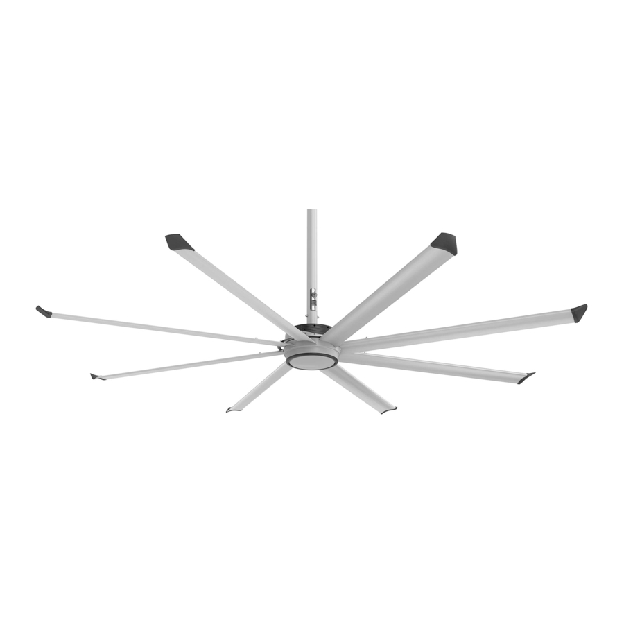
BIG ASS FANS Essence Manual
- Installation manual (72 pages) ,
- Installation manual (176 pages)
Advertisement

UPPER MOUNT & EXTENSION TUBE
Refer to the instructions included for your mounting structure.
FAN & SAFETY CABLE
If your fan order included guy wires, install them according to the instructions included with the guy wire kit.
Do not remove main fan unit from protective packaging prior to hanging.

TIGHTEN HARDWARE
Bar Joist Mounting

- Allow extension tube to hang freely and balance itself, and then tighten.
Wood Frame Mounting

- Allow extension tube to hang freely and balance itself, and then tighten.
Solid Beam Mounting

- Allow extension tube to hang freely and balance itself, and then tighten.
If installing the Essence LED Light (available in select regions only), install it according to the instructions included with the light. Contact Big Ass Fans for details.
WIRING HARNESSES & COVER PLATE
Make sure power is disconnected.
If installing Essence with UV-C Technology, do not install the cover plate provided with the fan.

LOWER COVER
Do not install lower cover if installing the LED light.

Remove protective cover sheet from bottom of main fan unit before installing lower cover.
AIRFOILS
If installing the LED light, install it before installing the airfoils.
Do not fully tighten bolts until all retainers are attached. Tighten outer bolts first.

Hole A should be positioned over top of hole B.

WALL CONTROLLER WIRING
Skip this step if installing Essence with UV-C Technology. Refer to the instructions provided with the UV-C light.

FAN WIRING
Wire Color Chart
| AC Line (L1) | AC Line/Neutral (L2/N) | Earth/PE | |
| North America 100–120 V System | Black | White | Green or Bare Copper |
| North America 208–240 V System | Black, Red, or Blue | Red, Blue, or Black R | |
| Australia | Brown or Red | Black or Light Blue | Green with Yellow Tracer |
| All Other Regions | Brown | Blue |
Power

Online Wiring Diagrams:
bigassfans.com/support/essence

Fire Relay
If installing Essence with UV-C Technology, do not connect fire relay wiring. Refer to the instructions provided with the UV-C light.

In the configuration shown, fan operation is disabled when power is applied to the fire relay. To restart the fan and clear the fire fault, close the circuit and turn off power to the fan for 60 seconds.
WALL CONTROLLER
Make sure the CAT5 controller cable is routed from the junction box to the controller installation location. Refer to the instructions that came in the controller box for controller installation details.
REPLACING FUSES
Suitable replacements

| Input Power and Required Breaker | Full Load Amps |
| 110–125 V, 50/60 Hz, 1 Ф, 10 A | 6.0 A |
| 200–240 V, 50/60 Hz, 1 Ф, 10 A | 3.6 A |
Documents / Resources
References
Download manual
Here you can download full pdf version of manual, it may contain additional safety instructions, warranty information, FCC rules, etc.
Advertisement


Need help?
Do you have a question about the Essence and is the answer not in the manual?
Questions and answers