BIG ASS FANS Isis Installation Manual
Hide thumbs
Also See for Isis:
- Installation manual (60 pages) ,
- Installation manual (112 pages) ,
- Installation manual (56 pages)

Subscribe to Our Youtube Channel
Related Manuals for BIG ASS FANS Isis


Summary of Contents for BIG ASS FANS Isis
- Page 1 INSTALLATION GUIDE Isis ® For help, call 1-877-BIG-FANS or visit www.bigassfans.com...
- Page 2 Isis ® Installation Checklist Did a structural engineer approve the mounting structure? See page 7 for Big Ass Fans-approved mounting structures. Will the fan be installed so that the airfoils are at least 10 ft (3.05 m) above the floor? Will the fan be installed so that the airfoils have at least 2 ft (0.61 m) of clearance from...
-
Page 3: Contact Information
Isis and the Isis logo are trademarks of Delta T Corporation, registered in the United States. All other trademarks used herein are the properties of their respective owners. No part of this document may be reproduced or translated into a different language without the prior written consent of Big Ass Fan Company. The information contained in this document is subject to change without notice. For the most up-to-date information, see the online Isis Installation Guide at www.bigassfans.com. -
Page 4: Important Safety Instructions
CAUTION: Exercise caution and common sense when powering the fan. Do not connect the fan to a damaged or hazardous power source. Do not attempt to resolve electrical malfunctions or failures on your own. Contact Big Ass Fans if you have any questions regarding the electrical installation of this fan. -
Page 7: Table Of Contents
Wiring the Fan (240 V, 50 Hz Isis) Wiring the Fan (240 V, 50/60 Hz Isis Mounting the Wall Controller (120 V Isis) Mounting the Wall Controller (240 V, 50 Hz Isis) Mounting the Wall Controller (240 V, 50/60 Hz Isis) WWW.BIGASSFANS.COM ©2014 DELTA T CORP. -
Page 8: Fan Operation
Isis ® Contents Fan Operation 120 V Isis ® 240 V, 50 Hz Isis 240 V, 50/60 Hz Isis Changing the Fan Direction Alternative Wiring Limited Access Application Limited Access Fan Controller and Controller Remote Operation Methods (120 V Isis ®... -
Page 9: About This Fan
Our never-ending commitment to quality and innovation keeps us at the leading edge of a burgeoning industry. With an eye to helping customers satisfy their needs, and a strong sense of corporate responsibility to the community, Big Ass Fans has redefined the way business is done. -
Page 10: What's In The Box
3. Safety clips and carabiners are only used when the top of the mounting structure is inaccessible. 4. Winglets are standard on Isis fans; however, airfoil tips are available as an option. Winglets or airfoil tips are installed on the airfoils during airfoil ®... -
Page 11: Parts Included
1. The safety cable is attached to the extension tube with a 3/8” bolt and nut. 2. Optional. L-Brackets or the Wood Frame Mounting kit are included only if ordered. Note: L-Bracket hardware is customer-supplied. Big Ass Fans recommends using 1/2”- 13 or M12 Grade 8 hardware. -
Page 12: Alternative Mounting Methods
I-Beam Adapter The I-beam adapter can be purchased for hanging the Isis from I-beams. Big Ass Fans offers both a small and large adapter depending on the width of the I-beam. The I-Beam Adapter can only be used on I-beams that are 5” (12.7 cm) to 9-7/8” (25 cm) (small adapter) or 9-7/8”... -
Page 13: Tools Needed
Isis ® Pre-Installation (cont.) Tools needed Big Ass Fans recommends gathering the following tools prior to beginning installation. Mechanical installation Electrical installation Standard and metric wrench sets Phillips and flat head screwdrivers #10 to #14 AWG strippers Standard and metric socket and ratchet sets Medium size channel locks Torque wrench capable of 29 ft·lb (39.3 N·m) -
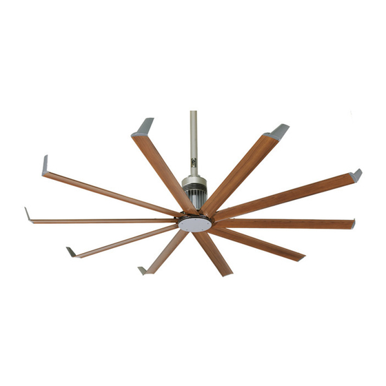
Page 14: Fan Diagram
C. Main fan unit. Includes motor, hub, lower mount, and power wire. D. Airfoil. Provides air movement. The unique, patented design provides efficient and effective air movement. E. Winglet. Improves the efficiency of the fan. Winglets are standard on Isis fans; however, airfoil tips are available as an option. -
Page 15: Preparing The Work Site
• If installing a 120 V fan on a typical lighting circuit with one basic light switch in which the critical red conductor or “traveler” is absent, you will need to purchase the Limited Access Controller. Please discuss this option with your Big Ass Fans representative. - Page 16 Notes...
-
Page 17: Select Proper Angle Irons
A structural engineer should verify that the mounting structure is adequate prior to fan installation. Verifying the stability of the mounting structure is the sole responsibility of the customer and/or end user, and Big Ass Fans hereby expressly disclaims any liability arising therefrom, or arising from the use of any materials or hardware other than those supplied by Big Ass Fans or otherwise specified in these installation instructions. -
Page 18: Pre-Drill Angle Irons
Isis ® Mounting Structure: Bar Joists (cont.) 2. Pre-drill angle irons Drill two Ø 7/16” (1.1 cm) holes exactly 5-1/2” (14 cm) apart in the centers of two angle irons. Measure the distance between the mounting points of the roof structure that the angle irons will span. Measure the same distance on the angle irons, and drill Ø... -
Page 19: 4A. Fasten Single Angle Irons To Roof Structure Mounting Points
Fasten the angle irons to the roof structure mounting points at each end with customer-supplied Grade 8 hardware as shown. Do not tighten the hardware until the fan has been mounted to the angle irons. Note: Big Ass Fans recommends orienting the angle irons so that the horizontal legs are facing each other. -
Page 20: 4B. Fasten Double Angle Irons To Roof Structure Mounting Points
Isis ® Mounting Structure: Bar Joists (cont.) 4b. Fasten double angle irons to roof structure mounting points CAUTION: The angle irons must be fastened to the roof structure at each end. Fasten the angle irons to the roof structure mounting points at each end with customer-supplied Grade 8 hardware as shown. Do not tighten the hardware until the fan has been mounted to the angle irons. -
Page 21: Attach Upper Mount (To Angle Irons)
Isis ® Mounting Structure: Bar Joists (cont.) 5. Attach upper mount (to angle irons) Secure the upper mount directly to the angle irons using the Mounting Hardware as shown. Consult the diagrams below for distances between the angle irons. Tighten the Mounting Hardware to 25 ft·lb (33.9 N·m) using a torque wrench with a 17 mm socket. -
Page 22: Identify Mounting Location
CAUTION: Do not install the fan from a single beam or a conduit box. Locate the area on the beams from which the fan will hang. Big Ass Fans recommends mounting the fan so that the airfoils are at least 10 ft (3 m) from the floor. -
Page 23: 2B. Fasten Brackets (To Floor Joists)
Isis ® Mounting Structure: Wood Frame (cont.) 2b. Fasten brackets (to floor joists) Note: This method should be used when the tops of the joists are inaccessible. Fasten the brackets to the mounting points on the floor joists using the Wood Frame Mounting Hardware as shown. Torque to 25 ft·lb (33.9 N·m). -
Page 24: Attach Upper Mount (To Wood Framing Channels)
Isis ® Mounting Structure: Wood Frame (cont.) 3. Attach upper mount (to wood framing channels) When cutting the wood framing channels, be sure the holes on each end will line up with the holes on the mounting brackets! Loosely attach the extension tube to the upper mount to determine where on the channels the mount should be attached. Fasten the mount to the wood framing channels using the Mounting Hardware as shown. -
Page 25: Fasten Wood Framing Channels (To Brackets)
Isis ® Mounting Structure: Wood Frame (cont.) 4. Fasten wood framing channels (to brackets) CAUTION: The center-to-center distance between the two beams or joists between which the fan will hang cannot be greater than 24” (61 cm). Fasten the wood framing channels to the brackets using the Wood Frame Mounting Hardware as shown. Torque to 25 ft·lb (33.9 N·m). -
Page 26: Determine Bracket Orientation
A structural engineer should verify that the structure is adequate prior to fan installation. Verifying the stability of the mounting structure is the sole responsibility of the customer and/or end user, and Big Ass Fans hereby expressly disclaims any liability arising therefrom, or arising from the use of any materials or hardware other than those supplied by Big Ass Fans or otherwise specified in these installation instructions. -
Page 27: 3A. Attach L-Brackets (To Mounting Structure)
Isis ® Mounting Structure: Solid Beam (cont.) 3a. Attach L-brackets (to mounting structure) Fasten the L-brackets to the mounting structure using the customer-supplied 1/2-13 or M12 L-Bracket Hardware as shown below. Note: L-bracket orientation may differ from the illustration. L-Bracket Hardware (Customer-Supplied): a. -
Page 28: Attach Extension Tube (To Upper Mount)
Isis ® Hanging the Fan 1. Attach extension tube (to upper mount) Pull the safety cable that is attached to the extension tube through the upper mount, and then fasten the extension tube to the upper mount (already attached to the mounting structure) using the Extension Tube Upper Hardware as shown. -
Page 29: 2C. Secure Safety Cable (To Solid Beam)
Isis ® Hanging the Fan (cont.) 2c. Secure safety cable (to solid beam) WARNING: The safety cable is a crucial part of the fan and must be installed correctly. If you have any questions, call Customer Service. Secure the safety cable to the mounting structure by wrapping it around the structure and securing the loose end with the Gripple as shown. -
Page 30: Attach Guy Wire Clamps
Isis ® Installing Guy Wires Guy wires may not be included in your fan order. They are intended to restrain the fan’s lateral movement and are only included in fan orders that have extension tubes 4 ft (1.2 m) or longer. Depending on the operational environment (wind, mounting structure, etc.), guy wires may be needed regardless of extension tube length. -
Page 31: Attach Locking Carabiners To Guy Wire Clamps
Isis ® Installing Guy Wires (cont.) 2. Attach locking carabiners to guy wire clamps Secure the four (4) locking carabiners to the guy wire clamps as shown. Securely tighten the carabiners. 3a. Attach beam clamp (bar joist mounting) The guy wire should be at a 45° angle from the extension tube (see the illustrations on the following page). -
Page 32: Route Guy Wire Through Gripple
Isis ® Installing Guy Wires (cont.) 4. Route guy wire through Gripple ® Route the guy wire through the Gripple and the carabiner on the guy wire clamp, and then back through the Gripple as shown below. Do not tighten the Gripple until the remaining guy wires have been installed. -
Page 33: Attach Winglets Or Airfoil Tips (To Airfoils)
Isis ® Installing Airfoils Big Ass Fans recommends completing electrical installation (p. 27) before installing the airfoils. WARNING: Disconnect power to the fan before installing the airfoils. 1. Attach winglets or airfoil tips (to airfoils) Note: Winglets are standard on Isis fans;... -
Page 34: Attach Airfoils (To Main Fan Unit)
Isis ® Installing Airfoils (cont.) 3. Attach airfoils (to main fan unit) After the fan is completely assembled and securely hanging from the mounting structure, peel off the protective plastic from the bottom of the hub. WARNING: Disconnect power to fan before installing airfoils. -
Page 35: Electrical Installation Safety
WARNING: Exercise caution and common sense when powering the fan. Do not connect the fan to a damaged or hazardous power source. Do not attempt to resolve electrical malfunctions or failures on your own. Contact Big Ass Fans if you have any questions regarding the electrical installation of this fan. -
Page 36: Wiring: Single Fan Application (120 V Isis ® )
Isis ® Electrical Installation (cont.) Wiring: single fan application (120 V Isis ® CAUTION: The fan must operate on a dedicated circuit with a dedicated neutral. Failure to install the fan on a dedicated circuit will cause the fan to operate improperly. -
Page 37: Wiring: Multi-Fan Application (120 V Isis)
Isis ® Electrical Installation (cont.) Wiring: multi-fan application (120 V Isis ® CAUTION: The fan must operate on a dedicated circuit with a dedicated neutral. Failure to install the fan on a dedicated circuit will cause the fan to operate improperly. -
Page 38: Wiring The Fan (240 V, 50 Hz Isis)
Isis ® Electrical Installation (cont.) Wiring the fan (240 V, 50 Hz Isis ® Before wiring the controller, temporarily attach the mounting plate to the wall box and pull the wires through the center. CAUTION: The fan must operate on a dedicated circuit with a dedicated neutral. Failure to install the fan on a dedicated circuit will cause the fan to operate improperly. -
Page 39: Wiring The Fan (240 V, 50/60 Hz Isis
Isis ® Electrical Installation (cont.) Wiring the fan (240 V, 50/60 Hz Isis ® CAUTION: The fan must operate on a dedicated circuit with a dedicated neutral. Failure to install the fan on a dedicated circuit will cause the fan to operate improperly. -
Page 40: Mounting The Wall Controller (120 V Isis)
Do not overtighten the Controller screws. Snap the wallplate to the controller. Wallplate Mounting the wall controller (240 V, 50 Hz Isis ® WARNING: Disconnect power to the wall box before wiring the fan controller. -
Page 41: V, 50/60 Hz Isis
To decrease fan speed, press the left side of the fan speed bar. Wall Controller with Wallplate 240 V, 50 Hz Isis ® To start the fan, press the button on the controller. When the power is turned on, the status light will illuminate. -
Page 42: Changing The Fan Direction
Cooling season The cooling effect created by the breeze from Isis fans keeps occupants comfortable with the thermostat at a higher setting. During the cooling season, every degree higher that the thermostat is reset reduces the energy consumed by the air conditioner by 1.5–2%. To minimize energy usage during the cooling season, operate the fan only when building occupants are present. -
Page 43: Limited Access Application
This wiring method should have been noted at the time of order. If not, contact Big Ass Fans Customer Service. -
Page 44: Limited Access Fan Controller And Controller Remote Operation
® Limited access fan controller and controller remote operation As a convenience, the fan controller and the controller remote sets are factory paired by Big Ass Fans. See the previous page for wiring instructions. To start the fan, tap the upper portion of the pushpad once. The fan may take up to 30 seconds to start rotating. To increase fan speed, press and hold the upper portion of the pushpad. -
Page 45: Way Single Fan Application
Isis ® Alternative Wiring Methods (120 V Isis ) (cont.) ® 3-way single fan application CAUTION: The fan must operate on a dedicated circuit with a dedicated neutral. Failure to install the fan on a dedicated circuit will cause the fan to operate improperly. -
Page 46: Annual Preventive Maintenance
Isis ® Preventive Maintenance WARNING: Before servicing or cleaning unit, switch power off at service panel and lock the service disconnecting means to prevent power from being switched on accidentally. When the service disconnecting means cannot be locked, securely fasten a prominent warning device (such as a tag) to the service panel. -
Page 47: General Troubleshooting
For questions about your product or customer service inquiries, For questions about your product or customer service inquiries, please call our toll free number (877-BIG-FANS) or visit please contact your local Big Ass Fans representative or fill out a www.bigassfans.com/service. contact form at www.bigassfans.com/service. -
Page 48: Replacing Fuses
Isis ® Troubleshooting (cont.) Replacing fuses WARNING: Ensure power is disconnected before replacing fuses. To replace the fuses on the main fan unit, remove the screw securing the fuse cover. Replace the appropriate fuse, and reinstall the cover. Refer to the table below for fuse recommendations. Note: If your fan’s fuse cover is in a different location than shown below, contact Customer Service for assistance. -
Page 49: Annual Maintenance Checklist
Annual Maintenance Checklist Fan Model: Fan Model: Fan Model: Serial #: Serial #: Serial #: Location: Location: Location: Date Initials Date Initials Date Initials... -
Page 51: Optional Parts
Optional Parts Order Form Fully complete this form, and then fax to Big Ass Fans at 859-967-1695. A Big Ass Fans representative will phone or e-mail you with the total cost of part(s) and shipping. Credit card information will also be obtained at that time. -
Page 53: Warranty Return Instructions
Replacement of products under warranty acknowledgment & return instructions If you believe a part failed during normal operation and is covered under warranty, Big Ass Fans will ship a replacement part to you pursuant to your notice that you will be replacing the original part within 10 days. The replacement part will be shipped to you prior to our receipt of the item that failed, and prior to our evaluation of this part to determine the reasons for its failure and whether it is covered under warranty. -
Page 54: Warranty Claim Form Instructions
The Warranty Claim Form will include our acknowledgment and a Return Materials Authorization (RMA) number. Do not return any item without first being assigned an RMA# by Big Ass Fans Customer Service. -
Page 55: Warranty Claim Form
800 Winchester Road Lexington, KY 40505 Phone: 1-877-BIG-FANS Fax: (859) 967-1695 www.bigassfans.com Warranty Claim Form Name (print): Signature: Company: Shipping Address: City/State/ZIP: Phone: Fax: Date of Items Returned: Purchase: Reason(s) for returning item (please provide detail, including length of time after fan had been in operation that problem was noticed, nature of problem, any attempts you made to remedy the problem, etc.): ATTENTION: Do not return any item without first being assigned an RMA# by Big Ass Fan Company Customer Service Department. -
Page 56: Responsibility Agreement
800 Winchester Road Lexington, KY 40505 Phone: 1-877-BIG-FANS Fax: (859) 967-1695 www.bigassfans.com Responsibility Agreement To: Big Ass Fan Company The undersigned understands and acknowledges receipt of the Warranty Claim Form and Instructions and agrees that Big Ass Fan Company has the right, upon receipt of returned merchandise, to make final determination as to whether this merchandise should be replaced at no cost under Big Ass Fan Company’s stated warranty policy. -
Page 57: Check-In Procedure
2348 Innovation Drive Lexington, KY 40511 Phone: 1-859-233-1271 www.bigasssolutions.com Check-In Procedure (for Big Ass Fans Certified Installers Only) ATTENTION: These items must be completed prior to any additional installation crew members entering jobsite or any installation material being unloaded. Date: Company:... - Page 58 Big Ass Fans or otherwise specified in the installation instructions. If this installation will be performed outside the scope of work or not within the specifications of Big Ass Fans by customer’s request, please provide specific details: Please sign below if both parties agree that all aspects of this installation have been thoroughly explained and are of clear understanding and agreement of the installation to be completed.
-
Page 59: Close-Out Procedure
2348 Innovation Drive Lexington, KY 40511 Phone: 1-859-233-1271 Close-Out Procedure www.bigasssolutions.com (for Big Ass Fans Certified Installers Only) Date: Company: Job Name: Address: Purchase Order No.: City/State/ZIP: Contact Name: Phone: E-mail: **SEE THE FOLLOWING PAGE FOR NFPA 13 REGULATIONS** The field crew supervisor and facility manager are to walk through the completed installation. - Page 60 (if applicable) Other (Please Explain Below) If any portion of this installation was performed outside the scope of work or not within the specifications of Big Ass Fans at any capacity or for any reason, please provide specific details below: Signatures of both parties are required below to acknowledge that this installation has been completed to customer’s satisfaction, to...
- Page 64 *004169-01* 004169-01 REV. D 2425 Merchant St., Lexington, KY 40511 1 (877) BIG-FANS | WWW.BIGASSFANS.COM...
Need help?
Do you have a question about the Isis and is the answer not in the manual?
Questions and answers