Table of Contents
Advertisement
Quick Links
Advertisement
Table of Contents

Subscribe to Our Youtube Channel
Related Manuals for JTS TG-10STX


Summary of Contents for JTS TG-10STX
-
Page 2: Table Of Contents
4. Parts Identification & Accessories ............5. Preparing procedures & basic operation ..........6. Recommendation..................... Thank you for choosing JTS wireless system. In order to obtain the best efficiency from the system, you are recommended to take few minutes to read this instruction manual carefully. -
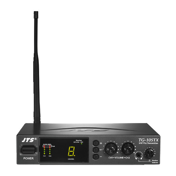
Page 3: Tg-10Stx Stationary Transmitter
.Do not handle the power cord with wet hands. .Keep the devices away from fire and heat sources. 2. Introduction The TG-10STX is an UHF PLL stantionary transmitter with 16 selectable channels. It works with all JTS 16 channel systems with channel indication 0,1,2..9,A,B..F. -
Page 4: Parts Identification & Accessories
Input Left / CH.1 14. Balanced XLR/Ø6.3mm Combo Input Right / CH.2 15. BNC Antenna Output Socket 16. Monitor input (mono Ø6.3mm phone jack) TG-10STX Monitor CH1/CH2 CH3 17. Input CH1 48V phantom power UHF PLL Transmitter AUDIO LEVEL switch... -
Page 5: Preparing Procedures & Basic Operation
5. Preparing procedures & basic operation (1.) Connect the main unit Connect the DC INPUT in the rear panel of TG-10STX to an AC to DC adaptor. (2.) Basic operation 1. Connect the mixer output to the XLR / Ø6.3mm combo CH1 input at the rear panel of TG-10STX with AF input cable. - Page 6 The user-friendly antenna comes with BNC connector. Connect the antenna on the rear of the transmitter and align ANTENNA OUT it upward. (5.) Power On / Off TG-10STX Monitor CH1/CH2 CH3 UHF PLL Transmitter AUDIO LEVEL Turn on or turn off the transmitter by...
-
Page 7: Loop Out Application
Multiple Systems Make use of the loop out connectors to deliver one signal from the mixer to multiple TG-10STX or other devices. 1. Connect the mixer outputs to inputs of the first transmitter. 2. Connect loop out connectors of the first transmitter to the second one. -
Page 8: Tg-10Srx Stationary Receiver
TG-10SRX Stationary Receiver 1. Important Cautions 1. Important Cautions . . . . 2. Features... -
Page 9: Specification
3. Specification Frequency Preparation..PLL Synthesized Control Carrier Frequency Range 502~960MHz S/N Ratio....... > 105dB T.H.D........<0.6%@1KHz Display........Display Contents....AF Level, Channel Controls........Power On/Off, Channel, Audio Level Audio Output Level... -12dB AF Output Impedance..600Ω Squelch........Pilot Tone & Noise Mute Operation Voltage.... -
Page 10: Preparing Procedures & Basic Operation
5. Preparing procedures & basic operation (1.) Power output connector Plug in one end of AC/DC adaptor cable to DC input socket in the rear panel of receiver, and plug another end into an AC outlet.(Step 1) (2.) Audio output connector Connect one end of the AF output cable to the AF output socket in the rear panel, then plug another end to the “MIC IN”... -
Page 11: Recommendation
(7.) Adjusting the AF output level Use the AF output level control located on the front side of the receiver to adjust the AF signel level that appears at output. (8.) DR-900 dual pack adaptor The dual rack adaptor is available to unify the half rack space into a standard EIA size with single or dual units.
Need help?
Do you have a question about the TG-10STX and is the answer not in the manual?
Questions and answers