Advertisement
Quick Links
Advertisement

Related Manuals for JTS RU-901Du


Summary of Contents for JTS RU-901Du
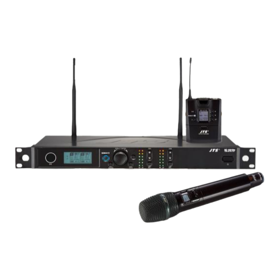
- Page 1 UHF PLL RU-901Du / Instruction Manual With JTS 2.4G RF Synchronizing Technology...
- Page 2 One year product warranty Product Model Equipment serial number Contact Customer number name Address Purchase date Selling store stamp Be sure to put store stamp and fill in purchase date for the warranty to be effective! Warranty description 1. Be sure to put the warranty label indicating purchase date on the bottom of equipment to ensure your interest in maintenance and service.
- Page 3 3. Specifications 3-1 UHF PLL Dual-channel True Diversity receiver// RU-901Du 3-2 UHF PLL hand-held transmitter // R-4TH 4. Description of parts 4-1 UHF PLL Dual-channel True Diversity receiver // RU-901Du 4-2 UHF PLL hand-held transmitter // R-4TH 4-3 Accessories 5.Connecting...
-
Page 4: Notes For System Operations
1. Notes for system operations • Before connecting to power, make sure the voltage marked on equipment is the same as that on the power socket. • Do not leave the unit at where the humidity and temperature are high. •... -
Page 5: Specifications
3. Specifications 3-1 UHF PLL Dual-channel True Diversity receiver // RU-901Du Frequency Oscillation Mode Phase-locked loop (PLL) Carrier Frequency Range 470~608MHz Remoset Frequency 2.4G RF Diversity True diversity Bandwidth 36MHz Signal/Noise Ratio >105dB(A) Total Harmonic Distortion (Thd) <0.6%@1KHz Receiving Sensitivity -95dBm ,... - Page 6 3-2 UHF PLL hand-held transmitter // Frequency oscillation Phase-locked loop, PLL Carrier frequency 470~608MHz Bandwidth 36MHz Paring RF Remoset RF power output Low / High RF stability <±10KHz@Fc Modulation frequency ±48KHz deviation Spurious Emissions <-50dBc Group, channels, frequency, mute, input level LCD display attenuation, sensitivity adjustment, power indication, Device ID...
-
Page 7: Description Of Parts
4. Description of parts 4-1 UHF PLL Dual-channel diversity receiver( True Diversity ) // RU-901Du Front panel Power ON/OFF: ON:push once to turn on. OFF:push and hold until ''Power OFF'' is shown on the LCD to turn off. EXIT: Push exit to cancel a selection or exit from the current menu when RU- 901Du is in the ''setting menu.''... - Page 8 Rear panel Power : AC power 100~240VAC AC power outlet(for cascading): it allows power connection to next receiver with an extension AC power cable. XLR audio jack: balanced audio signal output XLR audio jack: balanced audio signal output after mixing Ø6.3 audio output jack: unbalanced audio signal output Ø6.3 audio output jack: unbalanced audio signal output after mixing RF A (or B) Out: RF signal output socket(for cascading): Provide RF signal to next...
- Page 9 Content Displayed under the Non-Setting Mode: :Antenna Selection A/B. The Receiver is mute. : Transmitter Battery Level :Frequency (Group/Channel) : Frequency 520.325 : Key Lock (Key Lock ON) : Volume : Output attenuation ON Setup Menu RX1: Set the Receiver's Channel 1. RX2: Set the Receiver's Channel 2. 1: Set the Receiver's Channel 1.
- Page 10 4-2 UHF PLL handheld transmitter // Power ON/OFF:push once to turn on. Push and hold for 2 seconds while the power is on to turn off. While the power is on, a quick push of this button will show the Device ID on the LCD display. Mute:switch up to talk and down to mute while the power is on.
- Page 11 LCD displays RF output power (Low / High) Battery level Key lock Frequency (MHz) Indication of frequency, group and channel...
- Page 12 4-3 Accessories AC power cable * 1 BNC/BNC RF extension cable for cascading * 2 Extension AC power cable for series connection * 1 XLR(M)/XLR(F) Audio cable * 2 Antenna * 2 GC-80/GC-100 Guitar Cable Option GC-80L/GC-100L Guitar Cable Option SELF-MA N SM-018 WIRELESS MICROPHONE SYSTEM...
- Page 13 5. Preparing Procedures 5-1 How to connect the receiver// RU-901Du 1. Connect the audio output of receiver to mixer or amplifier 1.1RU-901Du: (1) The XLR output jack or 6.3mm unbalance output jack can be selected individually to connect the AF output to a mixer or amplifier for volume control.
- Page 14 Cascading of AC power cable and antenna It is allowed to cascade power and antennas for 5 units. Power socket More RU-901Dus… 5 units WIRELESS MICROPHONE SYSTEM...
- Page 15 5-2 Installing transmitter // The mute switch of handheld transmitter also serves to turn the power on. Therefore, the power will come on when the batteries are replaced. Place the mute switch at mute if you do not want to turn the power on immediately after battery replaced.
- Page 16 6. Instructions for use 6-1 How to use // RU-901Du Press and hold the SETUP key for 2 seconds to enter the Setup Menu. Trun the Rotary Switch to select the item to be set, and press SETUP again to enter the settings.
- Page 17 “Scan Results List”: Press the SETUP key to enter the menu screen and view the scan results. Select the available channels, and press the SETUP key to save the settings. Scanning the current Group: Upon entry into the screen, trun the Rotary Switch to select the group to be scanned, and press SETUP to start scanning.
- Page 18 ◎Microphone Options: Trun the Rotary Switch to select the item to be adjusted. Press SETUP, and then trun the Rotary Switch to select the settings to be adjusted, and then press SETUP to return to the item selection. Sensitivity Scope of Adjustment: -15dB~+15dB;Default Value is 0.
- Page 19 Automatic shutdown (when the Microphone is muted) This function is turned off. 1 min Automatic shutdown after 1 minute 10min Automatic shutdown after 10 minutes 30min Automatic shutdown after 30 minutes Synchronization Options Trun the Rotary Switch to select synchronize transmission of the setup items, and then press the SETUP key to perform the selection action.
- Page 20 ◎Display Settings Contrast 0~7 (Default Value4) Brightness 0~7 (Default Value4) ◎Mixed Output Mixed Output Enable Mixed Output Disable Mix the signal with RX1 and RX2 then output together from RX2 ◎Reset to original manufacturer settings ◎Device ID Device ID: 0~255: this setting affects the use of REMOSET; both the receiver and transmitter must be on the same Device ID before REMOSET is available.
- Page 21 6-2 How to use Push and hold SET for 2 seconds to enter the setting mode. Push SET repeatedly to locate the desired item. Use▲/▼for parameter settings. Push SET again to save the changes and exit. ◎ FREQ: frequency setting Increment of 1MHz Select with▲/▼...
- Page 22 ◎ RFP: RF power of microphone rF Lo Low(default) rF Hi High RFP low RFP Hi ◎ Device ID ID OFF Device ID deactivated ID 0~255 Device ID 0 ~ 255 ◎ Remoset (ON/OFF) Syn on Remoset activated Syn oFF Remoset deactivated Indicator Green: power is sufficient, >...
-
Page 23: Notes For The Product
7. Notes for the product For the best signal receiving quality, always keep the receiver within 3m of the transmitter. The receiver and transmitter shall be away from other metal objects, preferably 50cm or farther. Do not point the microphone directly to a speaker, or there will be feedbacks. It is recommended to hold the transmitter (microphone) at the middle section for the best pickup. - Page 24 PROFESSIONAL CO., LTD. No. 148, 9th Industry Road, Ta-Li Industrial Park, Taichung City, Taiwan. Tel: 886-4-24938803 Fax: 886-4-24914890 E-mail: jts@jts.com.tw www.jts.com.tw...
Need help?
Do you have a question about the RU-901Du and is the answer not in the manual?
Questions and answers