Table of Contents
Advertisement
Advertisement
Table of Contents

Subscribe to Our Youtube Channel
Related Manuals for JTS UF-20R


Summary of Contents for JTS UF-20R
- Page 1 PROFESSIONAL CO., LTD UF-20R / UF-20S / JSS-20 / UF-20TB No.148, Gongye 9th Rd., Dali Dist., TA-LI Industrial Park Professional Wideband (75MHz) Taichung City 41280, Taiwan (R.O.C.) True Diversity System Tel: 886-4-24938803 Fax: 886-4-24914890 Email: jts@jts.com.tw www.jts.com.tw 59508-072-03...
- Page 2 UF-20R / UF-20S / JSS-20 / UF-20TB Product manual...
- Page 3 One year product warranty Equipment Product Model serial number Customer Contact name number Address Purchase date Selling store Be sure to put store stamp and fill in purchase date for the warranty to be stamp effective! Warranty description 1. Be sure to put the warranty label indicating purchase date on the bottom of equipment to ensure your interest in maintenance and service.
-
Page 4: Table Of Contents
3-4 Charger For JSS-20 & UF-20TB ............. 6 3-5 Optional Condenser Microphone 4. Parts Identification & Accessories ......9 .............. 9 4-1 Receiver // UF-20R/UF-20S ............15 4-2 Handheld Transmitter // JSS-20 ..........17 4-3 Body-Pack Transmitter // UF-20TB ....19 4-4 Optional 2-Slot Charger / 8-Slot Charger // CH-2/CH-8 ............. -
Page 5: System Operation Instructions
Keep the equipment away from fire and heat source. • Transmitter and receiver need to be adjusted to the same “default channel” or “frequency”. 2. Features 2-1 UHF PLL Wideband True Diversity Receiver // UF-20R/UF-20S • UHF true diversity technology renders 200-480 meters of operation distance •... -
Page 6: Handheld Transmitter // Jss-20
Adjustable transmission power between Low and High • The panel Lock-On function prevents tampering and RF interruption • Together with JTS various music instrument mics, headset mics and tie clip mics this bodypack is versatile for all applications. NEWEST FEATURE: •... -
Page 7: Specification
3. Specification 3-1-1. Dual Channel Wideband True Diversity Receiver // UF-20R Frequency Preparation....PLL Synthesized Control Frequency Setting......JTS patented obstacles-free RF REMOSET Carrier Frequency Range..UHF 470~960MHz Channel..........Dual Bandwidth.......... 60~75MHz Wideband S/N Ratio..........>108dB(A) T.H.D............. <0.5%@1KHz Chassis........... - Page 8 3-1-2. Single Channel Wideband True Diversity Receiver // UF-20S Frequency Preparation....PLL Synthesized Control Frequency Setting......JTS patented obstacles-free RF REMOSET Carrier Frequency Range..UHF 470~960MHz Channel..........Single Bandwidth.......... 60~75MHz Wideband S/N Ratio..........>108dB(A) T.H.D............. <0.5%@1KHz Chassis........... 1/2U standard metal chassis Preset Channels / Group..
-
Page 9: Handheld Transmitter // Jss-20
3-2 Professional Wideband Handheld Transmitter // JSS-20 Frequency Preparation....PLL Synthesized Control Carrier Frequency Range..UHF 470~960 MHz Bandwidth.......... 60~75MHz Wideband RF Outputs........Low / High Stability..........<±10KHz Frequency Deviation....±48KHz (Peak) LCD Display........Group, Channel, Frequency, Battery Status, User Name, GAIN Adjust Controls.......... -
Page 10: Charger For Jss-20 & Uf-20Tb
3-4 Optional Charger For JSS-20 & UF-20TB & PS-20 Model No....... CH-2 ( 2-Slot Charger ) Input........... AC 100~240V, 0.4A max Output........DC 12V, 1A Model No....... CH-8 ( 8-Slot Charger ) Input........... AC 100~240V, 1.2A max Output........DC 15V, 3A 3-5 Optional Condenser Microphone Lavaliere Microphone Model No....... - Page 11 Headset Microphone Model No....... CM-214i CM-214Ui CM-214ULi Connector....... 801C4 801C4 801C4 (4P Mini XLR) (4P Mini XLR) (4P Mini XLR) Frequency Response..60~15,000 Hz 30~18,000 Hz 100 ~ 18,000Hz Polar Pattern......Omni-directional Cardioid Cardioid Sensitivity (at 1000Hz) -60±3 dB -68±3 dB -65±3 dB Impedance......
- Page 12 Ear-hook Microphone Model No....... CM-801/CM-804i CM-8015/CM-825i Connector......801C4 (4P Mini XLR) 801C4 (4P Mini XLR) Frequency Response..60~15,000 Hz 50~18,000 Hz Polar Pattern......Omni-directional Omni-directional Sensitivity (at 1000Hz) -64±3 dB -53±3 dB Impedance......1.8kΩ 1.8kΩ Max. SPL for 1% THD 130dB 130dB Compatible Instrument Microphone...
- Page 13 Power : Power on: Push the Power button to turn on Power off: Push and hold the Power button until “Power Off ” shows on the LCD EXIT key: Push EXIT to cancel the selection and exit the menu when the UF-20R is in the “Setting Menu. ”...
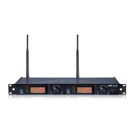
- Page 14 UF-20R PUSH / CONTROL PUSH / CONTROL wireless receiver SETUP EXIT SETUP EXIT UF-20R UF-20S...
- Page 15 4-1-2. Description of receiver LCD display Display color: Red: (1) No RF signal is received from any transmitter, and the LCD shows: No Signal (2) Transmitter on mute. Mic Mute (3) Transmitter battery low. Orange: RF and AF signals are received from transmitters. Professional Wideband True Diversity System (75MHz)
- Page 16 : Panel Lock On activated on receiver. : It indicates antenna A or B is receiving signal; is shown when no signal is received from a microphone. : receiver volume. : device ID: from 0 to 255. : transmitter battery level is shown when no signal is received from transmitter or the transmitter is mute.
- Page 17 4-1-3. Back panel // UF-20R POWER: AC power, 100 ~ 240VAC AC power outlet(for cascading): it allows power connection to next receiver with an extension AC power cable. AF OUTPUT BALANCED: XLR balanced audio output jack AF OUTPUT BALANCED: Ø6.3mm balanced audio output jack Antenna A (or B) In: antenna input (or antenna booster jack + 12VDC/150mA);...
- Page 18 4-1-4. Back panel // UF-20S Power receptacle: connect to power supply (DC12V/1000mA) Balanced XLR MIC output Ø 6.3mm balanced output BNC antenna socket: ANT 1 and ANT 2, set antennas vertical or sloping for better reception. Freq.Range: Made in Taiwan...
-
Page 19: Handheld Transmitter // Jss-20
4-2 Buttons and LCD Displays of UHF PLL Handheld Transmitter // JSS-20 4-2-1. Panel functions LCD display SET: set and save handheld transmitter 、 : up and down buttons to select the desired function of the handheld device. Power (1) Handheld transmitter on Power on: push the Power button. - Page 20 4-2-2. Description of LCD display Device ID: from 0 to 255 Sensitivity: -15dB ~ +15dB Low Cut indication Transmission Power: Hi (High) and Lo (Low) User name Battery level: in 5 levels G: the group in use, from 1 to 15 CH: the channel in use, ID23 up to 63...
- Page 21 4-3 Buttons and LCD Displays of UHF PLL Body-Pack Transmitter // UF-20TB 4-3-1. Panel functions LCD display Battery level Red: battery low; replace battery REMOSET indicators Blue: Remoset transmitting (approximately 5 seconds) Power: (1)On: push the power button Off: push and hold the power button for 2 seconds till the display shows “Power Off.
-
Page 22: Body-Pack Transmitter // Uf-20Tb
4-3-2. Description of LCD display Transmission Power: Hi (High) and Lo (Low) User Name Indicate current Group and current Channel Frequency: it shows the RF frequency Battery level: in 5 levels Sensitivity Value Low Cut indication Attenuate Indication UF-20TB Lock On Statue G: 1 C: 11 633.875 MHz... -
Page 23: Optional 2-Slot Charger / 8-Slot Charger
4-4 Optional 2-Slot Charger / 8-Slot Charger // CH-2/CH-8 LED Indicator Full Charged / Standby:Green Charging:Flash Green Fault:Flash Red *Charging Time:3 hours CH-2 CH-8 Professional Wideband True Diversity System (75MHz) -
Page 24: Optional Condenser Microphone
4-5 Optional Condenser Microphone Lavaliere Microphone // CM-501 / CM-201i / CM-125i Clip 4 Pin Mini XLR Windscreen CM-501 CM-201i CM-125i... - Page 25 Headset Microphone // CM-214i / CM-214Ui / CM-214ULi / CM-235i / CX-504 Gooseneck Adjustable headband Headband 4 Pin Mini XLR Windscreen CM-214i CM-214Ui CM-214ULi Standard : 4 Pin Mini XLR CM-235i CX-504 Professional Wideband True Diversity System (75MHz)
- Page 26 Ear-hook Microphone // CM-801 / CM-804i / CM-8015 / CM-825i Boom Adjustable Headband Adjustable ear hook Detchable Cable Cable Clip CM-801 Windscreen 4 Pin Mini XLR CM-804i CM-8015 CM-825i...
- Page 27 Compatible Instrument Microphone // CX-500 / CX-500F / CX-520 / CX-508W / CX-516W Gooseneck Clip Bracket Volume Control Windscreen 4 Pin Mini XLR CX-500 CX-500F CX-520 CX-508W CX-516W Professional Wideband True Diversity System (75MHz)
- Page 28 4-6-1. Accessories for UF-20R AC power cable * 1 BNC/BNC RF extension cable for cascading * 2 Front antenna signal cable Option Extension AC power cable for series connection * 1 XLR(M)/XLR(F) Audio cable * 2 MA-935 Capsule adaptor Option...
- Page 29 4-6-2. Accessories for UF-20S AC/DC power adapter * 1: Switching power adapter AC IN: AC100~240V/50~60Hz DC OUT: DC12V/1000 mA XLR(M)/XLR(F) Audio cable * 1 MA-935 Capsule adaptor Option Rechargeable battery ( 4 or 16 batteries will be included when purchase CH-2 or CH-8 charger) CH-2 double-slot charger Option CH-8 8-slot charger...
-
Page 30: Connection Method
1. UF-20 output to a mixer or an amplifier: Audio cable: XLR or Ø 6.3mm audio cable, one end connects to audio output of UF-20R “AF OUTPUT BALANCED”, while the other end connects to audio input of a mixer or an ampli- fier. - Page 31 5-1-2. Receiver connection method // UF-20S 1. UF-20S output to a mixer or an amplifier: Audio cable: XLR or Ø 6.3mm audio cable, one end connects to audio output of UF-20S “AF OUTPUT BALANCED”, while the other end connects to audio input of a mixer or an ampli- fier.
- Page 32 5-2 Cascading of AC power cable and antenna (UF-20R Only) It is allowed to cascade power and antennas for 10 units. Power socket Freq.Range: Antenna B In Antenna A In RF B Out RF A Out CAUTION POWER RISK OF ELECTRIC SHOCK...
-
Page 33: Operation
(1) Push the REMOSET button and the blue indicator starts to flash, indicating the receiver is transmitting data (Figure 1). *When using the REMOSET function of UF-20R, it is recommended to carry out RE- MOSET one by one. This is to prevent the interference between the REMOSET signals and the failure of data transmitting. - Page 34 (2) REMOSET successful: the blue indicator on the transmitter is on for 3 seconds and that on the receiver stops flashing. Fig. 2 (3)REMOSET failed: Check the following when the blue indicator on the receiver flashes in a slow pace: 1)If the receiver and the transmitter are of the same frequency band.
-
Page 35: Menu Setting
6-1-3. Menu setting Push and hold the SETUP button for 2 seconds to enter the menu. (1) Turn the rotary switch clockwise or counterclockwise to select the desired function. Push the switch (or the SETUP button) to enter the setting screen. Push EXIT to return to the main menu if nothing is done. - Page 36 (2) Rotate the switch to select a group “G:” from 1 to 15. Setup Group Push the rotary switch to save the selected value. CH: 10 633.625MHz (3) Rotate the switch to select a channel “CH:” from up to Setup Group 63 channels.
- Page 37 #2. Clear Group: delete a group defined by us er 1. Custom Group (1) Rotate the rotary switch to “2. Clear Group. ” Push the 2. Clear Group 3. Return rotary switch to enter the “Clear Group” screen. Group: (2) Rotate the rotary switch to select the group to be deleted Rotary to select and push the rotary switch.
- Page 38 #2. Result List: view the scan result list 1. All Groups Rotate the rotary switch to “2. Result List. ” Push the rotary 2. Result List 3. Current Group switch and enter the menu screen to view the result. Select an 4.
- Page 39 6. Device ID: define the ID code of device 5. Squelch (1) Rotate the rotary switch to “6. Device ID. ” Push the rotary 6. Device ID 7. Mic Config switch (or SETUP) to enter the ID setting menu. 8. Volume (2) Rotate the rotary switch to select the ID from 0-255;...
- Page 40 (3. LowCut: base attenuation 1. Sensitivity Rotate the rotary switch to “3. LowCut. ” Push the rotary 2. Attenuate 3. Low Cut switch (or SETUP) to enter the adjustment menu. 4. RF Power Mic Low Cut The Low Cut is not set. Rotate the rotary switch one notch clockwise to select Mic Low Cut Low Cut (as shown on the right).
- Page 41 (2) Rotate the rotary switch to select and push the switch to check the selection; REMOSET only synchronizes on checked selections. □ Frequency □ Sensitivity □ Attenuate □ Low Cut □ RF Power □ Key lock □ UserName □ Save and Exit □...
- Page 42 9. Equalizer: equalizer settings 9. Equalizer (1) Rotate the rotary switch to “9. Equalizer. ” Push the rotary a. Output Level b. Antenna Power switch (or SETUP) to enter the setting menu. c. User Name (2) Rotate the rotary switch to select one of the following: Setup Equalizer Equalizer deactivated Decrease low frequency gain...
- Page 43 (2) Rotate the rotary switch to select the desired characters. User Name Push the rotary switch to confirm the selection, and the UF-20R screen jumps to the next character to be selected. Select Char:1/10 “blank” for positions where no character is needed. Push SETUP to save the setting.
- Page 44 e. Reset c. User Name (1) Rotate the rotary switch to “e. Reset” Push the rotary switch d. Contrast e. Reset (or SETUP) to enter the setting menu. f. Key Lock *Once reset, all the settings will be returned to factory This will erase all data defaults.
-
Page 45: Power Button
6-2 Handheld transmitter system operation setting // JSS-20 6-2-1 Power button (1) Turn on the power Power On: press POWER Power Off: press POWER for approx. Power 1 second till the screen displays “Power OFF. ” Fig. 3 Note: when pressing the POWER button, “Mute ON”... - Page 46 6-2-2 Menu function setting: press SET and it will enter into menu function setting after two seconds. (1) Press ▲、▼ Select the desired item. Press SET to enter into the pre-set option. (2) After entering into the menu, press ▲、▼ to adjust the values.
- Page 47 3.Sensitivity 1. Frequency 2. Group/Channel (1) Press ▲、▼ to “3. Sensitivity. ” Press SET to enter into the 3. Sensitivity setting screen. 4. Low Cut (2) Press ▲、▼ to adjust the sensitivity. Use 3 dB as unit modi- Sensitivity fication. After adjustment, press SET to save the setting; the range of 0 dB sensitivity is -15dB~+15dB.
- Page 48 6. Remoset 5. Device ID 6. Remoset Press ▲、▼ to select “6.Remoset” function. Press SET to enter 7. RF Power into the setting screen. 8. Contrast Remoset Press ▲: to turn on and use REMOSET. Press ▼: to turn off and REMOSET function cannot be used. The microphone will be more power-saving when not using REMOSET Remoset function.
- Page 49 8. Contrast 5. Device ID 6. Remoset (1) Press ▲、▼ to select“8. Contrast. ” Press SET to enter into the 7. RF Power screen for contrast adjustment. 8. Contrast (2) Press ▲、▼ to adjust the contrast. The higher the value, the LCD Contrast darker the color;...
-
Page 50: Handheld Transmitter // Jss-20
b. Reset 9. Light Time a. User Name Press ▲、▼ to “b. Reset” and select SET to enter the screen setting. b. Reset c. KeyLock Press ▲: select CONFIRM to reset the internal information of the This will erase all date from Mic handheld transmitter. - Page 51 6-3 Body-pack transmitter system operation setting // UF-20TB 6-3-1 To turn on UF-20TB body-pack transmitter (diagram 5) (1) To turn on the power: press the Power button. (2) To turn off the power: press the Power button for a while. The screen will display “Power OFF”...
- Page 52 2. Group / Channel Frequency Group/Chan (1) Press ▲、▼ to select “2. Group / Channel. ” Press SET to enter into the Sensitivity setting screen. Attenuate Low Cut (2) After entering into the screen, press ▲、▼ to select desire Group. Press Group/Chan SET for saving and change into the channel setting.
- Page 53 5. Low Cut Frequency Group/Chan (1) Press ▲、▼ to select“Low Cut. ” Press SET to enter into the “Low Cut” Sensitivity setting screen. Attenuate Low Cut Low Cut (2) Press ▲ to turn on the Low Cut function. Low Cut (3) Press ▼...
- Page 54 6. Remoset: to turn on/off the REMOSET Device ID Remoset (1) Press ▲、▼ to select REMOSET function. Press SET to enter into RF Power “Remoset” setting screen. Contrast Light Time Remoset (2) Press ▲: to turn on and REMOSET function can be used. (3) Press ▼: to turn off.
- Page 55 9. Light Time: the setting of the backlight time Device ID Remoset RF Power (1) Press ▲、▼ to select backlight time. Press SET to enter into “Light Contrast Light Time Time” screen. Light Time (2) Press ▲、▼ to select the backlight time; you can select “closed”, “5~30 seconds”(having 5 seconds as the unit of change) or “constant light.
- Page 56 12. Key Lock: setting of the keypad lock User Name Reset (1) Press ▲、▼ to the keypad lock. Press SET to enter into “key Lock” KeyLock screen for keypad lock setting. Exit KeyLock (2) Press ▲、▼ to select lock “ALL” , “Set & Power” only or lock “OFF”. Set &...
-
Page 57: Body-Pack Transmitter // Uf-20Tb
G: 1 C: 11 633.875 MHz IDoff -12dB UHF PLL Transmitter (3) Instrument Microphones The system is compatible with JTS various instrument microphones. For detail please refer to user’ s manuals of these microphones. Professional Wideband True Diversity System (75MHz) - Page 58 (4) Ear-hook Microphone 1. Lightweight Dual Ear Hook Microphone Try on whether the headset is fit. Adjust the headband to a suitable width. Tighten or loosen the curve of the ear-hook by twisting the loop or expanding it. Curve and bend the boom to fit your face. Attach the detachable cable to a suitable place by a cable clip.
-
Page 59: Product Notes
7. Product notes (1) To get the best signal performance, please keep at least 3 meters between a receiver and a transmitter. (2) Keep a receiver and transmitter from other metal object for at least 50cm. (3) To prevent feedback and whistle, please do not aim transmitter to speaker. (4) It is suggested to hold the middle section of transmitter (microphone) body to achieve the best pickup effect. -
Page 60: Important Notice
8. Important Notice (1) JTS offers wireless systems in a selection of bands that conform to the different government regulations of specific nations or geographic regions. These regulations help limit radio frequency (RF) interference among different wireless devices and prevent interference with local public communications channels, such as television and emergency broadcasts.
Need help?
Do you have a question about the UF-20R and is the answer not in the manual?
Questions and answers