
Subscribe to Our Youtube Channel
Related Manuals for JTS US-1000D


Summary of Contents for JTS US-1000D
- Page 1 PROFESSIONAL CO., LTD. US-1000D/Mh-8990(i)/PT-990B(mi) No. 148, 9th Industry Road, Ta-Li Industrial Park, Taichung City, Taiwan, R.O.C. Tel: 886-4-24938803 Fax: 886-4-24914890 E-mail: jts@jts.com.tw www.jts.com.tw 59508-005-08...
- Page 2 US-1000D UHF PLL WIRELESS SYSTEMS Instruction Manual...
- Page 3 Thank you for choosing the JTS wireless system. In order to obtain the best efficiency from the system, you are recommended to take a few minutes to read this instruction manual carefully.
-
Page 4: Table Of Contents
INDEX 1. Important Caution 2. Features 3. Specification 3-1 Receiver// US-1000D 3-2 Handheld Transmitter // Mh-8990(i) 3-3 Body-pack Transmitter // PT-990B(mi) 3-4 Optional Condenser Microphone 4. Part Identification & Accessories 4-1 Receiver// US-1000D 4-2 Handheld Transmitter // Mh-8990(i) 4-3 Body-pack Transmitter // PT-990B(mi) -
Page 5: Important Caution
1. Important Caution • Always make all connections before plugging the unit into an AC power outlet. • Do not leave the devices in a place either with high temperature or high humidity. • Always do not handle the power cord with wet hands ! •... -
Page 6: Specification
3. Specification 3-1 Receiver // US-1000D Frequency Preparation..PLL Synthesized Control Carrier Frequency Range 502~960 MHz S/N Ratio........> 105dB T.H.D..........<0.6%@1KHz Display........... Display Contents....Frequency, Antenna A/B, Mute Display, RF/AF Level Meter, Battery Fuel Gauge Controls........Power On/Off, Frequency Up/Down, Frequency Scan, Audio Level, Lock-on Audio Output Level..... -
Page 7: Body-Pack Transmitter // Pt-990B(Mi)
3-3 Body-pack Transmitter // PT-990B(mi) Frequency Preparation.... PLL Synthesized Control Carrier Frequency Range..502~960 MHz RF Outputs........10mW Stability..........±10KHz Frequency Deviation....±48KHz LCD Display........Frequency, Battery Fuel Gauge Controls..........Power On/Off, AF Level, Frequency Up/Down, Lock-on Mode. Spurious Emissions....<-50 dBC Audio Frequency Response 40~18,000 Hz... - Page 8 Headset Microphone Model No....... CM-214i CM-214Ui CM-214ULi Connector....... 801C4 4P Mini XLR 801C3 (3P Mini XLR) (4P Mini XLR) 801C4 (4P Mini XLR) 801CS (3.5 stereo plug) Option Connector... 801C3 (3P Mini XLR) 801CR 801CS (3.5 stereo plug) 801CR Frequency Response..60~15,000 Hz 30~18,000 Hz 100 ~ 18,000Hz...
- Page 9 Ear-hook Microphone Model No....... CM-801/CM-804i CM-8015/CM-825i Connector......801C4 (4P Mini XLR) 801C4 (4P Mini XLR) Option Connector... 801C3 (3P Mini XLR) 801C3 (3P Mini XLR) 801CS (3.5 stereo plug) 801CS (3.5 stereo plug) 801CR 801CR Frequency Response..60~15,000 Hz 50~18,000 Hz Polar Pattern......
-
Page 10: Part Identification & Accessories
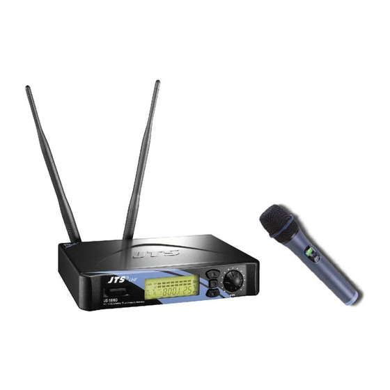
4. Parts Identification & Accessories 4-1 Receiver // US-1000D Power On/Off switch Up button (frequency adjustment) Down button (frequency adjustment) Set button (frequency adjustment) LCD Display Volume control DC socket for connection of main unit AF output, jack socket (AF UNBAL) -
Page 11: Body-Pack Transmitter // Pt-990B(Mi)
4-3 Body-pack Transmitter // PT-990B(mi) Mic. input Power On/Off switch Antenna LCD display Set button Up button Down button Battery tray button AF level control Belt clip Battery tray Attenuation pad (only for PT - 990Bmi) 4-4 Optional Condenser Microphone Lavaliere Microphone // CM-501 CM-201i CM-125i Clip 4 Pin Mini XLR... - Page 12 Headset Microphone // CM-214i CM-214Ui CM-214ULi CM-235i CX-504 Gooseneck Adjustable headband Headband 4 Pin Mini XLR Windscreen CM-214i CM-214Ui CM-214ULi Standard : 4 Pin Mini XLR 3 Pin Mini XLR 3.5 Stereo Plug CM-235i CX-504...
- Page 13 Ear-hook Microphone // CM-801 CM-804i CM-8015 CM-825i Boom Adjustable Headband Adjustable ear hook Detchable Cable Cable Clip CM-801 Windscreen 4 Pin Mini XLR 3 Pin Mini XLR Option 3.5 Stereo Plug Option 4Pin Hirose connecter Option CM-804i CM-8015 CM-825i WIRELESS MICROPHONE SYSTEM...
- Page 14 Compatible Instrument Microphone // CX-500 / CX-500F / CX-520 / CX-508W / CX-516W Gooseneck Clip Bracket Volume Control Windscreen 4 Pin Mini XLR CX-500 CX-500F CX-520 CX-508W CX-516W...
-
Page 15: Accessories
4-5 Accessories AC/DC adaptor Switching Power Supply(100V~240V , 50~60Hz) Linear Power Supply (220V , 50Hz) Option Linear Power Supply (220V , 60Hz) Option Screwdriver DR-900 dual rack adaptor Option RP-900 panel cover Option AF output cable (with Ø6.3 plug at both ends) GC-80/GC-100 Guitar Cable Option GC-80L/GC-100L Guitar Cable... -
Page 16: Preparing Procedures & Basic Operation
5. Preparing Procedures & Basic Operation 5-1 Receiver // US-1000D (1) Power output connector Plug in one end of AC/DC adaptor cable to DC input socket in the rear panel of receiver, and plug another end into an AC outlet.(Step 1) - Page 17 They are to be placed on the bottom side of the receiver. (5) Connecting the antennas ANT.1 / ANT.2 The user-friendly US-1000D antenna comes with easy mount on socket for effortless con- nection. Connect two antennas on the back of the receiver and align them upward.
- Page 18 (9) Adjusting the AF output level Use the AF output level control located on the front side of the receiver to adjustthe AF signal level that appears at output. AF OUTPUT LEVEL (10) Dual Rack Adaptor set The dual rack adaptor is available to unify the half rack space into a standard EIA size with single or dual units.
-
Page 19: Handheld Transmitter // Mh-8990(I)
3. Setting Lock-on Press “SET” button three sec. re-press “SET” button three times, after these procedure Press “UP” button for lock-on mode and “DOWN” button for lock-off mode. Re-press “SET” button the“ ” will display on the LCD the lock function could stored. 4. - Page 20 (4) Setting group channel 1. Frequency displayed: 1-1 group set up Press “SET” button for three sec. till the “MHz” show up and then re-press “SET” but- ton till the group digit show up. Now you can press “UP” or “DOWN” button one sec. to increase or decrease group number 1-2 channel set up After 1-1 press “SET”...
- Page 21 (6) Setting sensitivity 1. Frequency displayed : Press “SET” button three sec. till “MHz” show up, re-press “SET” button the group digit starts flashing, after these procedure please press “SET” button again till frequency starts flashing then press “SET” to start the sensitivity setting. 2.
- Page 22 (8) Relieved Lock-on Press “SET” button three sec. till“ ” show up, then press “DOWN” button plus “SET” button to store the lock-on relieved. 1. Press any button the display shows“ ” during lock-on model. And it will not disap- peared either electric off.
-
Page 23: Body-Pack Transmitter // Pt-990B(Mi)
5-3 Body-pack Transmitter // PT-990B(mi) (1) Turning the transmitter on/off The on/off switch is located on the top of the transmitter. (2) Inserting and changing the battery 1. The battery tray is located on the back of the transmitter. 2. Hold on to both belt clip buttons to release it. 3. - Page 24 Plug the mini XLR on the microphone cable into the “MIC. IN” on the body-pack transmitter. MIC IN (5) Instrument Microphones The system is compatible with JTS various instrument microphones. For detail please refer to user’s manuals of these microphones.
- Page 25 (6) Ear-hook Microphone 1. Lightweight Dual Ear Hook Microphone Try on whether the headset is fit. Adjust the headband to a suitable width. Tighten or loosen the curve of the ear-hook by twisting the loop or expanding it. Curve and bend the boom to fit your face. Attach the detachable cable to a suitable place by a cable clip.
- Page 26 (7) Basic operation 1. Frequency adjusting 1-1 Hold SET button for 3 seconds to activate frequency. 1-2 Once you see “MHz” blanking, you are ready to select your desired frequency by using UP and DOWN buttons. 1-3 Press the SET button again to store your changes. 2.
-
Page 27: Recommendation
6. Recommendation (1) In order to achieve the optimum reception condition and also extend the operating distance, please leave a “open space” between the receiver and transmitter. (2) Keep the devices away from the metal objects or any interference sources, at least 50 cm. (3) To avoid the feed-back effect, don’t leave the mic. -
Page 28: Important Notice
(RF) interference among different wireless devices and prevent interference with local public communications channels, such as television and emergency broadcasts. (2) For information on bands available in your area, consult your local dealer or phone JTS. More information is also available at JTS’s website (www.jts.com.tw).
Need help?
Do you have a question about the US-1000D and is the answer not in the manual?
Questions and answers