Table of Contents
Advertisement
Quick Links
Download this manual
See also:
User Manual
Advertisement
Table of Contents

Related Manuals for JTS TG-10STX


Summary of Contents for JTS TG-10STX
- Page 1 PROFESSIONAL CO., LTD. No. 148, 9th Industry Road, Ta-Li Industrial Park, Taichung City, Taiwan, R.O.C. Tel: 886-4-24938803 Fax: 886-4-24914890 E-mail: jts@jts.com.tw 59508-064-02 www.jts.com.tw...
- Page 2 TG-10STX / TG-10SRX...
- Page 3 Thank you for choosing the JTS wireless system. In order to obtain the best efficiency from the system, you are recommended to take a few minutes to read this instruction manual carefully.
-
Page 4: Table Of Contents
INDEX TG-10STX Stationary Transmitter 1. Important Cautions 2. Introduction 3. Specification 4. Parts Identification & Accessories 5. Preparing procedures & basic operation 6. Loop Out Application TG-10SRX Stationary Receiver 1. Important Cautions 2. Features 3. Specification 4. Parts Identification & Accessories 5. -
Page 5: Important Cautions
• Keep the devices away from fire and heat sources. 2. Introduction The TG-10STX is an UHF PLL stantionary transmitter with 16. It works with all JTS 16 channel indication 0,1,2..9,A,B..F. Together with directional antenna UDA-49P, antenna booster UB-900 the... -
Page 6: Specification
3. Specification TG-10STX Carrier Frequency Range...... 470~960MHz RF Output Power........Hi / Low Nominal Frequency Deviation (modulation)..........±40KHz Audio Input Impedance......20KΩ Nominal Input Level........ -20 dBV Maximal Input Level......... 0 dBV LED Display........... AF Level, Channel Audio Input Connector...... -
Page 7: Parts Identification & Accessories
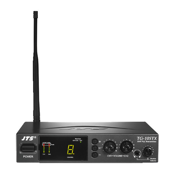
4. Parts Identification & Accessories TG-10STX Power On/Off switch LED Display Channel Selector Set button Volume control Monitor volume control 1/8” Stereo Phone Jack Antenna DC input ( 12~18V 600mA ) Balanced Loop Out Connector CH.1 Balanced Loop Out Connector CH.2 Balanced XLR/Ø6.3mm Combo... - Page 8 Optional Accessories RM-901 Rack Mount Kit RTF-1 Antenna Extension Cable...
-
Page 9: Preparing Procedures & Basic Operation
TG-10STX (1.) Connect the main unit Connect the DC INPUT in the rear panel of TG-10STX to an AC to DC adaptor. (2.) Basic operation 1. Connect the mixer output to the XLR / Ø6.3mm combo CH1 input at the rear panel of TG-10STX with AF input cable. - Page 10 AF Level of CH1 CH1/CH2 CH3 AF Level of CH2 Monitor channel display CHANNEL Channel display TG-10STX (4.) Attach the antenna The user-friendly antenna comes with BNC connector. Connect the antenna on the rear of the ANTENNA OUT transmitter and align it upward.
- Page 11 (9.) Set the rubber pad Four self-adhesive rubber pads are provided to ensure the stability. They are to be placed on the bottom of the transmitter. (10.) RTF-1 Antenna Extension Cable (Optional) Antenna extension cable enables front mounting antenna which benefits the RF effeciency.
-
Page 12: Loop Out Application
Multiple Systems Make use of the loop out connectors to deliver one signal from the mixer to multiple TG-10STX or other devices. 1. Connect the mixer outputs to inputs of the first transmitter. 2. Connect loop out connectors of the first transmitter to the second one. -
Page 13: Important Cautions
TG-10SRX Stationary Receiver 1. Important Cautions • Always make all connections before plugging the unit into an AC power outlet. • Do not leave the devices in a place with high temperature nor high humidity. • Keep the devices away from fire and heat sources. 2. -
Page 14: Specification
3. Specification TG-10SRX Frequency Preparation......PLL Synthesized Control Carrier Frequency Range......470~960MHz S/N Ratio............> 105dB T.H.D..............<0.6%@1KHz Display............... Display Contents......... AF Level, Channel Controls............Power On/Off, Channel, Audio Level Audio Output Level........-12dB AF Output Impedance......600Ω Squelch.............. Pilot Tone & Noise Mute Operation Voltage........ -
Page 15: Parts Identification & Accessories
4. Parts Identification & Accessories TG-10SRX Power On/Off switch Channel Selector Set button LED Display Volume control DC socket for connection of main unit AF output, Ø6.3mm phone jack socket (AF UNBAL) AF output, XLR socket (AF BAL) Antenna input socket Antenna AF OUTPUT BALANCED... - Page 16 Optional Accessories DR-900 Dual Rack Adaptor RP-900 Panel Cover GC-80/GC-100 Guitar Cable GC-80L/GC-100L Guitar Cable...
-
Page 17: Preparing Procedures & Basic Operation
5. Preparing procedures & basic operation TG-10SRX (1.) Power output connector Plug in one end of AC/DC adaptor cable to DC input socket in the rear panel of receiver, and plug another end into an AC outlet.(Step 1) (2.) Audio output connector Connect one end of the AF output cable to the AF output socket in the rear panel, then plug another end to the “MIC IN”... - Page 18 (5.) Connecting the antenna The user-friendly TG-10SRX antenna comes with easy mount on socket for effortless. Connect two antennas on the back of the the receiver and align them upward. ANT.1 / ANT.2 (6.)Turning the receiver on/off Turn the receiver on by pressing the “POWER” button.
-
Page 19: Recommendation
6. Recommendation 1. In order to achieve the optimum reception condition and also extend the operating distance, please leave on “open space” between the receiver and transmitter. 2. Keep the devices away from the metal objects or any interference sources, at least 50 cm. 3.
Need help?
Do you have a question about the TG-10STX and is the answer not in the manual?
Questions and answers