Supermicro SBM-GEM-X2C+ User Manual
Ethernet switch module
Hide thumbs
Also See for SBM-GEM-X2C+:
- Reference manual (985 pages) ,
- User manual (384 pages) ,
- Configuration manual (34 pages)
Table of Contents
Advertisement
®
SuperBlade
Network Modules
SBM-GEM-002 1-Gbps
SBM-GEM-001 1-Gbps
SBM-GEM-X2C+ 1/10-Gbps
Ethernet Pass-Through Module
Ethernet Switch Module
Ethernet Switch Module
SBM-XEM-F8X4SM 10-Gbps Ethernet Switch
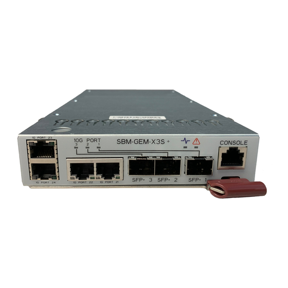
SBM-GEM-X3S+ 1/10-Gbps
Ethernet Switch Module
SBM-IBS-Q3616/Q3616M/Q3618/F3616M
SBM-XEM-X10SM 10-Gbps Ethernet Switch
4x QDR InfiniBand Switch Module
SBM-IBS-001 4x DDR
SBM-XEM-002/M 10-Gbps Ethernet
InfiniBand Switch Module
Pass-Through Module
SBM-IBP-D14 4x DDR InfiniBand
SBM-GEP-T20 1-Gbps Ethernet Pass-Through
Pass-Through Module
Module for TwinBlade™
User's Manual
Revison 1.1c
Advertisement
Table of Contents

Related Manuals for Supermicro SBM-GEM-X2C+


Summary of Contents for Supermicro SBM-GEM-X2C+
-
Page 1: Network Modules
® SuperBlade Network Modules SBM-GEM-002 1-Gbps SBM-GEM-001 1-Gbps SBM-GEM-X2C+ 1/10-Gbps Ethernet Pass-Through Module Ethernet Switch Module Ethernet Switch Module SBM-XEM-F8X4SM 10-Gbps Ethernet Switch SBM-GEM-X3S+ 1/10-Gbps Ethernet Switch Module SBM-IBS-Q3616/Q3616M/Q3618/F3616M SBM-XEM-X10SM 10-Gbps Ethernet Switch 4x QDR InfiniBand Switch Module SBM-IBS-001 4x DDR SBM-XEM-002/M 10-Gbps Ethernet InfiniBand Switch Module Pass-Through Module... - Page 2 This product, including software and documentation, is the property of Supermicro and/or its licensors, and is supplied only under a license. Any use or reproduction of this product is not allowed, except as expressly permitted by the terms of said license.
-
Page 3: About This Manual
About this Manual This manual is written for professional system integrators, Information Technology professionals, service personnel and technicians. It provides information for the installation and use of Supermicro's network modules. Installation and maintenance should be performed by experienced professionals only. Manual Organization Chapter 1: Introduction The first chapter provides an overview of this manual. - Page 4 Superblade Network Modules User’s Manual Notes...
-
Page 5: Table Of Contents
............... 1-1 1-1 Overview ..................... 1-1 1-2 Product Checklist of Typical Components ........1-1 1-3 Features ....................1-1 1-4 Contacting Supermicro ..............1-2 Chapter 2 Standardized Warning Statements ..... 2-1 2-1 About Standardized Warning Statements ........2-1 Warning Definition................... 2-1 Installation Instructions ................ - Page 6 Superblade Network Modules User’s Manual 3-4 Firmware for the 1/10 Gigabit and 10-Gigabit Ethernet Switch Modules ....................3-13 Firmware Upgrading Procedures ............3-13 Firmware Failure Recovery Steps ............3-16 Chapter 4 InfiniBand Modules ............4-1 4-1 Overview ..................... 4-1 4-2 SBM-IBS-001 4X DDR InfiniBand Switch Module .......
- Page 7 Ports...................... 5-16 Chapter 6 1-Gb Ethernet Switch Firmware ......6-1 6-1 SBM-GEM-001 Firmware Features and Functions ..... 6-1 6-1 Port Status ..................6-4 Port VLAN ID (PVID)................6-5 Jumbo Frames Support ................6-5 Port Configuration ................... 6-5 6-2 Statistics ....................6-7 Port Statistics ..................
- Page 8 Superblade Network Modules User’s Manual Top LED Display ..................7-7 Left Side Tree..................7-7 Middle Configuration Link Table.............. 7-8 7-4 System Management Page ............. 7-8 System Settings ..................7-10 System Settings ................. 7-10 System Version .................. 7-12 File Management .................. 7-13 Save Configuration................
- Page 9 RMON Basic Settings ................ 7-43 Event Configuration................7-44 RMON Alarm Configuration ............... 7-45 Ethernet Statistics Configuration ............7-46 History Control Configuration ............. 7-47 QoS....................... 7-48 QOS Basic Settings ................7-48 QOS Classmap Settings ..............7-49 QOS Policymap Settings..............7-50 COSQ Scheduling Algorithm.............. 7-51 COSQ Weight and Bandwidth Configuration ........
- Page 10 Superblade Network Modules User’s Manual Port Configuration ................7-81 GARP Timers ..................7-82 RSTP ....................7-83 RSTP Global Settings ................ 7-83 RSTP Basic Settings................7-84 Port Settings..................7-85 Port Status..................7-86 MSTP ....................7-87 MSTP Basic Settings ................. 7-87 MSTP Timers ..................7-89 Port Configuration ................
- Page 11 Address Settings ................7-117 Address Profile................. 7-118 Prefix Settings .................. 7-119 DHCP Server ..................7-120 DHCP Basic Settings ............... 7-120 Pool Settings ..................7-121 DHCP Relay..................7-122 DHCP Relay Basic Settings ............. 7-122 Interface Settings ................7-123 RIP ...................... 7-124 RIP Basic Settings ................
- Page 12 Superblade Network Modules User’s Manual BGP Community Management ............7-155 RRD ....................7-156 RRD Basic Settings................7-157 BGP....................7-158 RIP ....................7-159 OSPF ....................7-160 RRD6 ....................7-161 RRD6 Basic Settings................ 7-161 Filters ....................7-162 RRD V6 OSPF ................. 7-163 RRD RIP ..................
- Page 13 Interface ....................7-188 Interface Statistics ................7-188 Ethernet Statistics ................7-189 Radius....................7-191 TACACS+ Statistics ................7-193 RMON Ethernet Statistics ..............7-195 SNMP Statistics .................. 7-197 Agent....................7-197 SNMP AgentX .................. 7-198 VLAN....................7-199 Current DB ..................7-200 VLAN Port Statistics ................. 7-201 VLAN Multicast Table ...............
- Page 14 Superblade Network Modules User’s Manual OSPF ....................7-230 OSPF Route Information..............7-230 OSPF Link State DB................. 7-231 OSPFv3 ....................7-233 OSPFV3 Route Information ............. 7-233 OSPFV3 Link State DB ..............7-234 VRRP Statistics................... 7-235 IGMP Snooping................... 7-237 IGMP Snooping Clear Statistics ............7-237 IGMP Snooping V1/V2 Statistics............
- Page 15 Appendix B LED Descriptions ............B-1 B-1 Gigabit Ethernet Module LED Descriptions ........B-1 B-2 1/10 Gigabit Ethernet Module LED Descriptions ......B-2 B-3 SBM-XEM-X10SM 10G and SBM-XEM-F8X4SM Ethernet Switch LED Descriptions ..................B-3 B-4 SBM-IBS-001 InfiniBand Switch LED Descriptions .....B-4 B-5 SBM-IBS-Q3616M and SBM-IBS-Q3618M InfiniBand Switch LED Descriptions ....................B-5 Appendix C Installing Triple Wide Bays...
- Page 16 Superblade Network Modules User’s Manual Notes...
- Page 17 List of Figures Figure 3-1. Blade Enclosure with 1-Gbps Switch Modules Installed....3-2 Figure 3-2. Blade Enclosure with 1/10-Gbps Switch Modules Installed.... 3-3 Figure 3-3. Configuring the Switch Module ............3-4 Figure 3-4. IPMI Login Screen ................3-5 Figure 3-5. IPMI Blade System Screen............. 3-6 Figure 3-6.
- Page 18 Superblade Network Modules User’s Manual Figure 6-13. QoS Setting Screen ..............6-17 Figure 6-14. Rate Limit and Storm Control Screen ......... 6-18 Figure 6-15. Storm Control Screen ..............6-19 Figure 6-16. L2 Management Screen ............. 6-20 Figure 6-17. L2 Management: Current Entries Screen ........6-20 Figure 6-18.
- Page 19 Figure 7-31. SNMP Target Address Settings Page ........7-37 Figure 7-32. SNMP Target Parameter Settings Page........7-38 Figure 7-33. SNMP Security Settings Page ............ 7-39 Figure 7-34. SNMP Trap Settings Page............7-40 Figure 7-35. SNMP AgentX Subagent Settings Page........7-41 Figure 7-36.
- Page 20 Superblade Network Modules User’s Manual Figure 7-71. Garp Timers Configuration Page ..........7-82 Figure 7-72. Global Configuration Page............7-83 Figure 7-73. RSTP Configuration Page ............7-84 Figure 7-74. Port Status Configuration Page ..........7-85 Figure 7-75. RSTP Port Status Page .............. 7-86 Figure 7-76.
- Page 21 Figure 7-111. RIP Interface Page ..............7-125 Figure 7-112. RIP Neighbor List Page ............7-126 Figure 7-113. RIP Security Settings Page ............ 7-127 Figure 7-114. RIP Interface Specific Address Summarization Page..... 7-128 Figure 7-115. RIP6 Interface Configuration Page ......... 7-129 Figure 7-116.
- Page 22 Superblade Network Modules User’s Manual Figure 7-151. IGMP Snooping VLAN Router Ports Page ......7-171 Figure 7-152. MAC Based Multicast Forwarding Table Page ....... 7-172 Figure 7-153. Dynamic Multicast Global Configuration Page ....... 7-173 Figure 7-154. Dynamic Multicast Port Configuration Page ......7-174 Figure 7-155.
- Page 23 Figure 7-191. ICMP Statistics Page .............. 7-220 Figure 7-192. IPV6 Interface Statistics Page ..........7-222 Figure 7-193. ICMPv6 Statistics Page ............7-224 Figure 7-194. RIP Interface Statistics Page ..........7-226 Figure 7-195. RIP6 Interface Statistics Page ..........7-227 Figure 7-196. RIP6 Route Information Page..........7-228 Figure 7-197.
- Page 24 Superblade Network Modules User’s Manual Notes xxiv...
- Page 25 List of Tables Table 3-1. SBM-GEM-001 Switch Module Address Default Settings....3-7 Table 3-2. Locating and Identifying a Switch ............ 3-9 Table 3-3. SBE-710 Enclosures with SBM-GEM-001/002 or SBM-GEM-X2C+/ X3S+ ....................... 3-10 Table 3-4. SBE-710 Enclosures with SBM-XEM-X10SM........ 3-10 Table 3-5. SBE-720 Enclosures with SBM-GEM-X2C+/X3S+ ......3-10 Table 3-6.
- Page 26 Superblade Network Modules User’s Manual 5-15 Table 5-21. SBM-XEM-F8X4SM Ports............5-16 Table 6-1. SBM-GEM-001 Software Features and Functions......6-1 Table 6-2. Port Configuration Screen Controls ..........6-6 Table 6-3. Port Statistics Screen Controls ............6-8 Table 6-4. Port Mirroring Screen Controls ............6-15 Table 6-5.
- Page 27 Table 7-30. QOS Classmap Settings Page Parameters ......... 7-49 Table 7-31. QOS Policymap Settings Page Parameters ........ 7-50 Table 7-32. COSQ Scheduling Algorithm Settings Page Parameters .... 7-51 Table 7-33. COSQ Weight and Bandwidth Configurations Page Parameters 7-52 Table 7-34. NTP Settings Page Parameters........... 7-53 Table 7-35.
- Page 28 Superblade Network Modules User’s Manual Table 7-70. VLAN Interface Basic Settings Page Parameters...... 7-110 Table 7-71. IPv4 Interface Settings Page Parameters........7-111 Table 7-72. IP Route Configuration Page Parameters........7-112 Table 7-73. LoopBack Basic Settings Page Parameters ......7-113 Table 7-74. IP6 Route Configuration Page Parameters........ 7-114 Table 7-75.
- Page 29 Table 7-108. Advanced BGP Configuration Page Parameters ..... 7-154 Table 7-109. BGP Community Management Page Parameters ....7-156 Table 7-110. RRD Basic Settings Page Parameters ........7-157 Table 7-111. RRD BGP Configuration Page Parameters ......7-158 Table 7-112. RRD RIP Configuration Page Parameters....... 7-159 Table 7-113.
- Page 30 Superblade Network Modules User’s Manual Table 7-148. RSTP Information Page Parameters ........7-206 Table 7-149. RSTP Port Statistics Page Parameters ........7-207 Table 7-150. MSTP Information Page Parameters ........7-209 Table 7-151. MSTP CIST Port Statistics Page Parameters......7-210 Table 7-152. MSTP MSTI Port Statistics Page Parameters ......7-212 Table 7-153.
- Page 31 xxxi...
- Page 32 Superblade Network Modules User’s Manual Notes xxxii...
-
Page 33: Chapter 1 Introduction
• If you have any questions, please contact our support team at: support@supermicor.com Note: A complete list of safety warnings is provided on the Supermicro web site at http://www.supermicro.com/about/policies/safety_information.cfm. Features Chapter 4: "InfiniBand Modules" on page 4-1 for information and features of the InfiniBand modules. -
Page 34: Contacting Supermicro
Address: Super Micro Computer, Inc. 980 Rock Ave. San Jose, CA 95131 U.S.A. Tel: +1 (408) 503-8000 Fax: +1 (408) 503-8008 marketing@supermicro.com (General Information) Email: support@supermicro.com (Technical Support) Web Site: www.supermicro.com Europe Address: Super Micro Computer B.V. Het Sterrenbeeld 28, 5215 ML ‘s-Hertogenbosch, The Netherlands... -
Page 35: Chapter 2 Standardized Warning Statements
The following statements are industry standard warnings, provided to warn the user of situations which have the potential for bodily injury. Should you have questions or experience difficulty, contact Supermicro's Technical Support department for assistance. Only certified technicians should attempt to install or configure components. - Page 36 SBI-7127R-SH Blade Module User’s Manual Warnung WICHTIGE SICHERHEITSHINWEISE Dieses Warnsymbol bedeutet Gefahr. Sie befinden sich in einer Situation, die zu Verletzungen führen kann. Machen Sie sich vor der Arbeit mit Geräten mit den Gefahren elektrischer Schaltungen und den üblichen Verfahren zur Vorbeugung vor Unfällen vertraut.
-
Page 37: Installation Instructions
Chapter 2: Standardized Warning Statements BELANGRIJKE VEILIGHEIDSINSTRUCTIES Dit waarschuwings symbool betekent gevaar. U verkeert in een situatie die lichamelijk letsel kan veroorzaken. Voordat u aan enige apparatuur gaat werken, dient u zich bewust te zijn van de bij een elektrische installatie betrokken risico's en dient u op de hoogte te zijn van de standaard procedures om ongelukken te voorkomen. -
Page 38: Circuit Breaker
SBI-7127R-SH Blade Module User’s Manual מתח את הוראות התקנה לפני חיבור המערכת למקור יש לקרוא ﻣﺼﺪر ﻟﻠﻄﺎﻗﺔ اﻟﻨﻈﺎم إﻟﻰ ﻗﺒﻞ ﺗﻮﺻﯿﻞ ﺘﺮﻛﯿﺐ اﻗﺮ إرﺷﺎدات اﻟ Waarschuwing Raadpleeg de installatie-instructies voordat u het systeem op de voedingsbron aansluit. Circuit Breaker Warning! This product relies on the building's installation for short-circuit (overcurrent) protection. -
Page 39: Power Disconnection Warning
Chapter 2: Standardized Warning Statements ﻓﻲ اﻟﺘﻲ ﺗﻢ ﺗﺜﺒﯿﺘﮭﺎ ﻣﻦ اﻟﺪواﺋﺮاﻟﻘﺼﯿﺮة اﻟﺤﻤﺎﯾﺔ ﻣﻌﺪات ﯾﻌﺘﻤﺪ ﻋﻠﻰ ھﺬا اﻟﻤﻨﺘﺞ اﻟﻤﺒﻨﻰ أﻛﺜﺮ ﻣﻦ ﻟﯿﺲ ﻮﻗﺎﺋﻲ اﻟ اﻟﺠﮭﺎز ﺗﻘﯿﯿﻢ أن ﺗﺄﻛﺪ ﻣﻦ 20A, 250V Waarschuwing Dit product is afhankelijk van de kortsluitbeveiliging (overspanning) van uw electrische installatie. -
Page 40: Equipment Installation
SBI-7127R-SH Blade Module User’s Manual ¡Advertencia! El sistema debe ser disconnected de todas las fuentes de energía y del cable eléctrico quitado de los módulos de fuente de alimentación antes de tener acceso el interior del chasis para instalar o para quitar componentes de sistema. Attention Le système doit être débranché... -
Page 41: Restricted Area
Chapter 2: Standardized Warning Statements Warnung Das Installieren, Ersetzen oder Bedienen dieser Ausrüstung sollte nur geschultem, qualifiziertem Personal gestattet werden. ¡Advertencia! Solamente el personal calificado debe instalar, reemplazar o utilizar este equipo. Attention Il est vivement recommandé de confier l'installation, le remplacement et la maintenance de ces équipements à... - Page 42 SBI-7127R-SH Blade Module User’s Manual Warnung Diese Einheit ist zur Installation in Bereichen mit beschränktem Zutritt vorgesehen. Der Zutritt zu derartigen Bereichen ist nur mit einem Spezialwerkzeug, Schloss und Schlüssel oder einer sonstigen Sicherheitsvorkehrung möglich. ¡Advertencia! Esta unidad ha sido diseñada para instalación en áreas de acceso restringido. Sólo puede obtenerse acceso a una de estas áreas mediante la utilización de una herramienta especial, cerradura con llave u otro medio de seguridad.
-
Page 43: Battery Handling
Chapter 2: Standardized Warning Statements Battery Handling Warning! There is the danger of explosion if the battery is replaced incorrectly. Replace the battery only with the same or equivalent type recommended by the manufacturer. Dispose of used batteries according to the manufacturer's instructions. 警告... -
Page 44: Redundant Power Supplies
SBI-7127R-SH Blade Module User’s Manual Waarschuwing Er is ontploffingsgevaar indien de batterij verkeerd vervangen wordt. Vervang de batterij slechts met hetzelfde of een equivalent type die door de fabrikant aanbevolen wordt. Gebruikte batterijen dienen overeenkomstig fabrieksvoorschriften afgevoerd te worden. Redundant Power Supplies Warning! This unit might have more than one power supply connection. -
Page 45: Backplane Voltage
Chapter 2: Standardized Warning Statements اﻣﺪاد اﻟﻄﺎﻗﺔ ﺑﻮﺣﺪات ﻋﺪة اﺗﺼﺎﻻت ﺠﮭﺎز اﻟ ﯾﻜﻮن ﻟﮭﺬا ﻗﺪ اﻟﻜﮭﺮﺑﺎء ﻋﻦ ﻮﺣﺪة اﻟ ﻟﻌﺰل ﻛﺎﻓﺔ اﻻﺗﺼﺎﻻت ﯾﺠﺐ إزاﻟﺔ Waarschuwing Deze eenheid kan meer dan één stroomtoevoeraansluiting bevatten. Alle aansluitingen dienen verwijderd te worden om het apparaat stroomloos te maken Backplane Voltage Warning! Hazardous voltage or energy is present on the backplane when the system is... -
Page 46: Comply With Local And National Electrical Codes
SBI-7127R-SH Blade Module User’s Manual اﻟﻠﻮﺣﺔ أواﻟﻄﺎﻗﺔ اﻟﻤﻮﺟﻮدة ﻋﻠﻰ اﻟﺘﯿﺎر اﻟﻜﮭﺮﺑﺎﺋﻲ ﻣﻦ ﺧﻄﺮ ھﻨﺎك ھﺬا اﻟﺠﮭﺎز ﺧﺪﻣﺔ ﻛﻦ ﺣﺬرا ﻋﻨﺪ ﯾﻌﻤﻞ اﻟﻨﻈﺎم ﻋﻨﺪﻣﺎ ﯾﻜﻮن Waarschuwing Een gevaarlijke spanning of energie is aanwezig op de backplane wanneer het systeem in gebruik is. Voorzichtigheid is geboden tijdens het onderhoud. Comply with Local and National Electrical Codes Warning! Installation of the equipment must comply with local and national electrical... -
Page 47: Product Disposal
Chapter 2: Standardized Warning Statements Waarschuwing Bij installatie van de apparatuur moet worden voldaan aan de lokale en nationale elektriciteitsvoorschriften. Product Disposal Warning! Ultimate disposal of this product should be handled according to all national laws and regulations. 警告 本产品的废弃处理应根据所有国家的法律和规章进行。 警告... -
Page 48: Hot Swap Fan Warning
SBI-7127R-SH Blade Module User’s Manual Waarschuwing De uiteindelijke verwijdering van dit product dient te geschieden in overeenstemming met alle nationale wetten en reglementen. Hot Swap Fan Warning Warning! The fans might still be turning when you remove the fan assembly from the chassis. -
Page 49: Power Cable And Ac Adapter
Electrical Appliance and Material Safety Law prohibits the use of UL or CSA -certified cables (that have UL/CSA shown on the code) for any other electrical devices than products designated by Supermicro only. 警告... - Page 50 Fehlfunktion oder ein Brand entstehen. Elektrische Geräte und Material Safety Law verbietet die Verwendung von UL-oder CSA-zertifizierte Kabel, UL oder CSA auf der Code für alle anderen elektrischen Geräte als Produkte von Supermicro nur bezeichnet gezeigt haben.
- Page 51 Het gebruik van andere kabels en adapters kan leiden tot een storing of een brand. Elektrisch apparaat en veiligheidsinformatiebladen wet verbiedt het gebruik van UL of CSA gecertificeerde kabels die UL of CSA die op de code voor andere elektrische apparaten dan de producten die door Supermicro alleen. 2-17...
- Page 52 SBI-7127R-SH Blade Module User’s Manual Notes 2-18...
-
Page 53: Chapter 3 Setup And Installation
This chapter covers the setup and installation of the SuperBladeSuperBlade Ethernet switch modules. SuperMicro has three different Gigabit Ethernet switch modules for its SuperBlade system. The first is the SBM-GEM-001 Gigabit Ethernet switch module with ten external 1-Gbps Ethernet uplinks. The second SBM-GEM-X2C(+) and third SBM-GEM-X3S+ 1/ 10-Gigabit Ethernet switch modules are a 1-Gbps Ethernet switches with three external 10-Gbps uplink and two/four external 1-Gbps Ethernet uplink ports. -
Page 54: Figure 3-1. Blade Enclosure With 1-Gbps Switch Modules Installed
Superblade Network Modules User’s Manual Figure 3-1. Blade Enclosure with 1-Gbps Switch Modules Installed SBM-GEM-001 Switch SBM-IBS-001 4x DDR InfiniBand Switch Module... -
Page 55: Removing A Switch Module
Chapter 3: Setup and Installation Figure 3-2. Blade Enclosure with 1/10-Gbps Switch Modules Installed SBM-GEM-X2C(+) Switch SBM-XEM-002M Pass-Through Module 5. Push the release handle to the closed position. NOTE: After the module has been installed and the handle locked, it will turn on and a POST test will run to verify it is working properly. -
Page 56: Configuring The Switch Module
Superblade Network Modules User’s Manual Configuring the Switch Module Figure 3-3. Configuring the Switch Module A Gigabit Ethernet switch module can be configured using two methods (as shown in Figure 3-3). You may configure it: • Through the web-based management utility or IPMI (via the CMM module) •... -
Page 57: Web-Based Management Utility/Ipmi
Chapter 3: Setup and Installation Web-based Management Utility/IPMI Using the Web-based Management Utility or IPMI is the most user-friendly method of configuring the switch module. You can access the configuration menu either through the management utility or by a network connection. See either Chapter 6 Chapter 7... -
Page 58: Figure 3-5. Ipmi Blade System Screen
Superblade Network Modules User’s Manual a. Type in your Username in the U box. SERNAME b. Type in your Password in the P box and click on L ASSWORD OGIN NOTE: The default username and the default password are both ADMIN. The Default IP address is https://192.168.100.102. -
Page 59: Address Defaults
Chapter 3: Setup and Installation Figure 3-6. Gigabit Switch Panel Address Defaults The following defaults in Table 3-1 are the default addresses that are initially set. Afterwards, you can change these values within the program. Table 3-1. SBM-GEM-001 Switch Module Address Default Settings Address Default Setting Default IP Address... -
Page 60: Command Line
Superblade Network Modules User’s Manual Command Line Configuring the 1/10-G Ethernet switch (SBM-GEM-X2C/SBM-GEM-X3S+) or the 10-G Ethernet switch (SBM-XEM-X10SM) can be done using a command line via telnet or by using the serial console interface. Accessing CLI through Telnet: To access command line via telnet, follow the below steps. 1. -
Page 61: Locating And Identifying Switches And Switch Ports On A Blade Enclosure
Chapter 3: Setup and Installation Locating and Identifying Switches and Switch Ports on a Blade Enclosure Use this section to help you in locating and identifying the switch ports and switches on a blad enclosure. Locating and Identifying a Switch on a Blade Enclosure When you are looking at the rear of the blade enclosure, you can identify the switch associating with a CMM designation by using the information in Table... -
Page 62: Table 3-3. Sbe-710 Enclosures With Sbm-Gem-001/002 Or Sbm-Gem-X2C+/X3S
Superblade Network Modules User’s Manual Table 3-3. SBE-710 Enclosures with SBM-GEM-001/002 or SBM-GEM-X2C+/X3S+ Blade Upper Switch Lower Switch Switch Port # Blade1 NIC1 NIC2 Gi 0/1 Blade 2 NIC1 NIC2 Gi 0/2 Blade 3 NIC1 NIC2 Gi 0/3 Blade 4 NIC1 NIC2 Gi 0/4... -
Page 63: Table 3-6. Sbe-720 Enclosures With Sbm-Xem-X10Sm
Chapter 3: Setup and Installation Table 3-5. SBE-720 Enclosures with SBM-GEM-X2C+/X3S+ Blade Upper Switch Lower Switch Switch Port # Blade 8 NIC1 NIC2 Gi 0/8 Blade 9 NIC1 NIC2 Gi 0/9 Blade 10 NIC1 NIC2 Gi 0/10 Blade 11 NIC1 NIC2 Gi 0/11 Blade 12... -
Page 64: Table 3-7. Sbe-714 Enclosures With Sbm-Gem-001/002 Or Sbm-Gem-X2C+/X3S
Superblade Network Modules User’s Manual Table 3-6. SBE-720 Enclosures with SBM-XEM-X10SM (Continued) Blade Upper Switch Lower Switch Switch Port # Blade 18 NIC2 NIC1 Ex 0/18 Blade 19 NIC2 NIC1 Ex 0/19 Blade 20 NIC2 NIC1 Ex 0/20 Table 3-7. SBE-714 Enclosures with SBM-GEM-001/002 or SBM-GEM-X2C+/X3S+ Blade Upper Switch Lower Switch... -
Page 65: Firmware For The 1/10 Gigabit And 10-Gigabit Ethernet Switch Modules
Chapter 3: Setup and Installation Firmware for the 1/10 Gigabit and 10-Gigabit Ethernet Switch Modules The firmware for the 1/10-Gigabit and 10-Gigabit Ethernet switch modules resides on a chip on the PCB. The switch modules have internal flash memory in two areas to hold two firmware images. -
Page 66: Figure 3-7. Displayed Text For Rebooting
Superblade Network Modules User’s Manual Booting using a Fallback Firmware Image: Use the procedure below to boot using a fallback firmware image. 1. Reboot the switch by power cycling the switch power. 2. During reboot, press any key when it displays the below text (as shown in Figure 3-7). -
Page 67: Figure 3-8. Setting Hardware Information
Chapter 3: Setup and Installation NOTE: The numbers in the Product Type entry change depending upon the switch you are using. 3. Once the boot sequence is interrupted, it will display menu options as shown in Figure 3-7. Use the "H" option to set hardware information by typing the character H. This will display the hardware information that can be changed as shown in Figure 3-8. -
Page 68: Firmware Failure Recovery Steps
Superblade Network Modules User’s Manual 8. In case you wish to later move back to a normal image, repeat the above the steps with one difference for step 4, where you should use the command rflag=0 instead of rflag=1 to boot with a normal firmware image. Upgrading Fallback Firmware using TFTP: To upgrade fallback firmware using TFTP, use the procedure below. - Page 69 Chapter 3: Setup and Installation 4. Configure the IP address for this switch (only for booting purposes) using the command: ip=<IP address> For example ip=https://192.168.2.3 5. Configure the subnet mask for this switch IP address using the below command: mask=<subnet mask> For example mask=255.255.255.0 6.
- Page 70 Superblade Network Modules User’s Manual Notes 3-18...
-
Page 71: Chapter 4 Infiniband Modules
Chapter 4 InfiniBand Modules Overview InfiniBand is a switch-based, point-to-point bidirectional serial link network communications architecture. Supermicro offers three different Infiniband modules: • 4X DDR (20-Gb/s) switch with 14 internal ports and 10 external CX4 ports • 4X DDR (20-Gb/s) pass-through with 14 internal ports and 14 external CX4 ports •... -
Page 72: Sbm-Ibs-001 4X Ddr Infiniband Switch Module
Superblade Network Modules User’s Manual SBM-IBS-001 4X DDR InfiniBand Switch Module Figure 4-1. SBM-IBS-001 InfiniBand Switch Module Table 4-1. SBM-IBS-001 InfiniBand Module Interface Item Description Module Power LED Module Status LED External InfiniBand Port (10 total) Port Physical Link LED (Green) Port Activity LED (Yellow) Module Release Handle Table 4-2. -
Page 73: Sbm-Ibs-Q3618/Q3616 4X Qdr Infiniband Switch Modules
Chapter 4: InfiniBand Modules SBM-IBS-Q3618/Q3616 4X QDR InfiniBand Switch Modules Figure 4-2. SBM-IBS-Q3618/Q3616 InfiniBand Switch Module Table 4-3. SBM-IBS-Q3618/Q3616 InfiniBand Module Interface Item Description System error. Fault LED (Red) System status. Ready LED (Green) External InfiniBand Port (16 QSFP ports for Q3616 and 18 QSFP ports for Q3618) Per Port Dual-color LED, PHY link(Green)/Logic link(Amber)/ACT blinking(Green+Amber) Module Release Handle Port Numbers (First port number is top port, second port number is bottom port) -
Page 74: Sbm-Ibs-Q3618M/Sbm-Ibs-Q3616M 4X Qdr Infiniband Switch Modules
Superblade Network Modules User’s Manual SBM-IBS-Q3618M/SBM-IBS-Q3616M 4X QDR InfiniBand Switch Modules Figure 4-3. SBM-IBS-Q3616M InfiniBand Switch Module Table 4-5. SBM-IBS-Q3618M/SBM-IBS-Q3616M InfiniBand Module Interface Item Description System error. Fault LED (Red) System status. Ready LED (Green) External InfiniBand Ports (16 QSFP ports for Q3616M and 18 QSFP ports for Q3618M) Per Port Dual-color LED, PHY link(Green)/Logic link(Amber)/ACT blinking(Green+Amber) Module Release Handle Internal CMM Module Ethernet Port... - Page 75 120W (with CMM Module Loaded) Operating System Firmware (upgradable) In addition to the InfiniBand switching capability it shares with other Supermicro Blade InfiniBand switches, the SBM-IBS-Q3618M/SBM-IBS-Q3616M modules include provision for the installation of an optional integrated Chassis Management Module (CMM). This “mini-CMM” (BMB-CMM-002) is installed as an add-on-module inside the switch chassis.
-
Page 76: Sbm-Ibs-F3616M 4X Qdr Infiniband Switch Module
Superblade Network Modules User’s Manual SBM-IBS-F3616M 4X QDR InfiniBand Switch Module Figure 4-4. SBM-IBS-F3616M InfiniBand Switch Module Table 4-7. SBM-IBS-F3616M InfiniBand Module Interface Item Description System error. Fault LED (Red) System status. Ready LED (Green) External InfiniBand Ports Per Port Dual-color LED, PHY link(Green)/Logic link(Amber)/ACT blinking(Green+Amber) Module Release Handle Internal CMM Module Ethernet Port Port Numbers (First port number is top port, second port number is bottom port) -
Page 77: Table 4-8. Sbm-Ibs-F3616M Infiniband Module Features
120W (with CMM Module Loaded) Operating System Firmware (upgradable) In addition to the InfiniBand switching capability it shares with other Supermicro Blade InfiniBand switches, the SBM-IBS-F3616M modules include provision for the installation of an optional integrated Chassis Management Module (CMM). This “mini-CMM”... -
Page 78: Sbm-Ibp-D14 Infiniband Pass-Through Module
Superblade Network Modules User’s Manual SBM-IBP-D14 InfiniBand Pass-Through Module Figure 4-5. SBM-IBP-D14 InfiniBand Pass-Through Triple-Wide Module The SBM-IBP-D14 InfniBand Pass-through Module is a triple-wide non-configurable pass-through module that includes fourteen (14) 4X DDR copper ports with CX-4 connectors. The pass-through module is used to provide a connection between the Infiniband controller (Add-on Card) mounted on the blade’s mainboard and an external InfiniBand device. -
Page 79: Installing/Removing The Infiniband Pass-Through Module
Chapter 4: InfiniBand Modules NOTE: The 10GbE Pass-through module (SBM-XEM-002/M) also requires the same double-wide bay as the InfiniBand switch module and may be installed instead of the InfiniBand switch module in your blade enclosure system. Use the same instructions below for installing either the pass-through module or the InfiniBand switch module. -
Page 80: Infiniband Switch Leds
Superblade Network Modules User’s Manual InfiniBand Switch LEDs InfiniBand switch LEDs are listed and described in Table B-5 Appendix Blade Software for Access to InfiniBand Switch Module The InfiniBand Switch Module is an unmanaged switch and requires no configuration. Blades which are to be connected to it will require an appropriate driver software package to be installed. -
Page 81: Chapter 5 Ethernet Modules
Chapter 5 Ethernet Modules Your SuperBlade enclosure can include either of several models of Ethernet switch modules or of Ethernet pass-through modules installed in it. The Ethernet switch modules and pass-through modules can only be installed in the upper and/or lower left module bays, whereas the SBM-XEM-002/M 10-Gigabit pass-through module must be installed in a double-wide slot in the enclosure in a location alternately used for the InfiniBand switch module. -
Page 82: Led Indicators
Superblade Network Modules User’s Manual Table 5-1. SBM-GEM-001 Gigabit Ethernet Switch Module Interface (Continued) Item Description Ethernet Port Status LEDs Module Release Handle Table 5-2. GEM-001 Gigabit Ethernet Switch Module Features Feature Description Chipset Broadcom BCM5345M Internal: Fourteen 1-Gbps downlink ports / External: Ten 1-Gbps RJ45 Internal/External Ports uplink ports Bandwidth... -
Page 83: Sbm-Gem-X2C(+) 1/10-Gb Ethernet Switch Module
Chapter 5: Ethernet Modules SBM-GEM-X2C(+) 1/10-Gb Ethernet Switch Module The SBM-GEM-X2C(+) 1/10-Gigabit Ethernet switch module is a layer 2/3 Ethernet switch. It includes three 10-Gb/s uplink ports (two CX4 and one SPF+), two 1-Gb/s uplink RJ45 uplink ports and fourteen (X2C) or twenty (X2C+) 1-Gb/s downlink ports for the SuperBlade's LAN interfaces. -
Page 84: Led Indicators
Superblade Network Modules User’s Manual Table 5-5. SBM-GEM-X2C(+) 1/10-Gigabit Ethernet Switch Module Features Feature Description Chipset Broadcom BCM56314 Internal: Twenty (X2C+) 1-Gbps downlink ports Internal/External Ports External: Two 1-Gbps RJ45 uplink ports and Three 10-Gbps uplink ports (1 SPF+, 2 CX4) Bandwidth 112-Gbps non-blocking Trunking... -
Page 85: Sbm-Gem-X3S+ 1/10-Gb Ethernet Switch Module
Chapter 5: Ethernet Modules SBM-GEM-X3S+ 1/10-Gb Ethernet Switch Module The SBM-GEM-X3S+ 1/10-Gigabit Ethernet switch module is a layer 2/3 Ethernet switch. It includes three 10-Gb/s uplink ports (SFP+), four 1-Gb/s uplink RJ45 uplink ports and twenty 1-Gb/s downlink ports for the SuperBlade's LAN interfaces. The Ethernet switch module has two internal Ethernet paths to the CMM(s). -
Page 86: Led Indicators
Superblade Network Modules User’s Manual Table 5-8. SBM-GEM-X3S+ 1/10-Gigabit Ethernet Switch Module Features Feature Description Chipset Broadcom BCM56314 Twenty 1-Gbps downlink ports Internal/External Ports External: Four 1-Gbps RJ45 uplink ports and Three 10-Gbps uplink ports (SFP+) Bandwidth 104-Gbps non-blocking Trunking Link aggregation support (Full 802.3 ad) Jumbo Frame Support Up to 9KB... -
Page 87: Sbm-Gem-002 1-Gb Ethernet Pass-Through Module
Chapter 5: Ethernet Modules SBM-GEM-002 1-Gb Ethernet Pass-through Module The SBM-GEM-002 Gigabit pass-through module is a non-configurable pass through module that includes fourteen (14) 1-Gb/s uplink (RJ45) ports and fourteen 1-Gb/s downlink ports for the SuperBlade's LAN interfaces. This Ethernet module has two internal Ethernet paths to the CMM(s). -
Page 88: Sbm-Xem-002/M 10-Gb Ethernet Pass-Through Module
Superblade Network Modules User’s Manual Table 5-11. SBM-GEM-002 Gigabit Ethernet Pass-through Module Features Feature Description Internal: Fourteen 1-Gbps downlink ports / External: fourteen 1-Gbps RJ45 Internal/External Ports uplink ports Remote Management Protocols Power Consumption ~30.6W SBM-XEM-002/M 10-Gb Ethernet Pass-through Module The SBM-XEM-002/M, and the newer SBM-XEM0-002M 10-Gigabit pass-through modules are non-configurable pass through modules that includes 14 (fourteen) 10-Gb/ s uplink (SFP+) ports and 14 10-Gb/s internal downlink (XAUI) ports for the... -
Page 89: Figure 5-5. Sbm-Xem-002/M 10-Gigabit Pass-Through Module
Chapter 5: Ethernet Modules NOTE: The SBM-XEM-002/M 10-Gigabit pass-through module must be connected to another 10-Gigabit Ethernet switch module in order to operate. If you connect it to a 10/100/1000 switch, it will not work. Figure 5-5. SBM-XEM-002/M 10-Gigabit Pass-through Module Table 5-12. -
Page 90: Sbm-Gep-T20 1-Gb Ethernet Pass-Through Module For Twin-Blade Modules
Superblade Network Modules User’s Manual SBM-GEP-T20 1-Gb Ethernet Pass-through Module for Twin-Blade Modules The SBM-GEP-T20 Gigabit pass-through module is a non-configurable pass through module that includes twenty (20) 1-Gb/s uplink (RJ45) ports and twenty (20) 1-Gb/s downlink ports for the SuperBlade's LAN interfaces. This Ethernet module has an internal I C path to the CMM. -
Page 91: Figure 5-7. Sbm-Gep-T20 Installed In Enclosure
Chapter 5: Ethernet Modules Table 5-15. SBM-GEP-T20 Gigabit Ethernet Pass-through Module Features Feature Description Internal: Twenty 1 Gbps downlink ports / External: twenty 1 Gbps RJ45 Internal/External Ports uplink ports (fixed speed at 1 Gbps) Remote Management Protocols Power Consumption ~30.6W The SBM-GEP-T20 is a double-wide module. -
Page 92: Sbm-Xem-X10Sm 10-Gb Ethernet Switch Module
Superblade Network Modules User’s Manual SBM-XEM-X10SM 10-Gb Ethernet Switch Module The SBM-XEM-X10SM 10-Gigabit Ethernet switch module is a layer 2/3 Ethernet switch. It offers advanced switching features and connection to 10-Gigabit Ethernet networks. Internally it connects to the SuperBlade through a one or two-port mezzanine add-on-card. -
Page 93: Led Indicators
Chapter 5: Ethernet Modules Table 5-17. SBM-XEM-X10SM 10 Gigabit Ethernet Switch Module Features Feature Description Chipset Broadcom BCM56820 Internal: Twenty 10-Gbps downlink ports Internal/External Ports External: Four (TwinBlade) or Ten (Ten Blade) 10-Gbps uplink ports (SPF+) Bandwidth 480-Gbps Trunking Link Aggregation Support (Full 802.3 ad) Jumbo Frame Support Up to 9KB Remote Management... -
Page 94: Sbm-Xem-F8X4Sm Converged Networking Switch Module
Data Center resources (LAN) and storage including 10GbE, FC and FCoE. This module provides visibility of the VMs in the storage fabric through vHBA capable Supermicro AOC-XEM-iN2 CNA cards, and it provides a high performance low latency architecture supporting a combined 482-Gbps switching bandwidth in full duplex operation. -
Page 95: Table 5-19. Sbm-Xem-F8X4Sm 10 Gigabit Ethernet Switch Module Interface
Chapter 5: Ethernet Modules Table 5-19. SBM-XEM-F8X4SM 10 Gigabit Ethernet Switch Module Interface Item Description Switch Fault Indicator LED Switch Available Indicator LED CMM Available Indicator LED Reset Button SFP+ 10-Gbps Uplink Ports SFP+ Fibre Channel (FC) Uplink Ports 10-Gbps Uplink Port Link Up/Available LED 10-Gbps Uplink Port Link Activity LED Switch Console USB Port KVM for CMM Port... -
Page 96: Led Indicators
Superblade Network Modules User’s Manual LED Indicators LED indicators for the SBM-XEM-F8X4SM 10-Gigabit Ethernet switch module are listed and described in Table B-4 Appendix Ports The SBM-XEM-F8X4SM 10-Gigabit Ethernet switch module contains several front-mounted ports as described below in Table 5-6. -
Page 97: Table 6-1. Sbm-Gem-001 Software Features And Functions
Chapter 6 1-Gb Ethernet Switch Firmware The firmware configuration system for the SBM-GEM-001 Gigabit Ethernet switch module is covered in this chapter. SBM-GEM-001 Firmware Features and Functions Table 6-1 provides a summary of features and functions for the Gigabit Ethernet switch module firmware. -
Page 98: Figure 6-1. Switch Status Screen
Superblade Network Modules User’s Manual To configure the switch, select the switch you want in the S screen in the WITCH TATUS Web-based Management Utility. See the Web-based Management Utility User’s Manual for details. screen will appear (Figure 6-1) in your browser. WITCH TATUS Figure 6-1. -
Page 99: Chapter 6 1-Gb Ethernet Switch Firmware
Chapter 6: 1-Gb Ethernet Switch Firmware NOTE: You will see “BMB-GEM-003” on most of these screens. This the board model number for the SBM-GEM-001 switch and is sometimes used interchangeably with it in describing the product. -
Page 100: Port Status
Superblade Network Modules User’s Manual Port Status The P screen provides a status overview of the switch’s 24 ports. As shown TATUS Figure 6-3, it includes link, speed, duplex, flow control, jumbo frame and PVID. In this screen click on P on the left menu bar. -
Page 101: Port Vlan Id (Pvid)
Chapter 6: 1-Gb Ethernet Switch Firmware Port VLAN ID (PVID) The PVID is used in a port-based VLAN to allow assigning a port to belong to a VLAN. A VLAN can then be configured to be a group of member ports. This switch is an 802.1q tag-aware switch. -
Page 102: Figure 6-5. Port Configuration Screen
Superblade Network Modules User’s Manual Figure 6-5. Port Configuration Screen Table 6-2. Port Configuration Screen Controls Control Description Port Specifies the port number to control. Admin Enables or disables the port. Enables or disables auto-negotiation. When auto-negotiation is enabled, the port negotiates with the link partner and works out speed, duplex operation, and flow Auto Negotiation control. -
Page 103: Statistics
Chapter 6: 1-Gb Ethernet Switch Firmware Statistics The S screen displays the total number of packets transmitted or received on TATISTICS each port as shown in Figure 6-6. Click on the R button to retrieve the current EFRESH count and update the screen. Click on the C button to reset the count to LEAR OUNTERS... -
Page 104: Figure 6-7. Port Statistics Screen
Superblade Network Modules User’s Manual Figure 6-7. Port Statistics Screen Table 6-3. Port Statistics Screen Controls Control Description Displays traffic information on outgoing frames. Octets Indicates total octets transmitted. UnicastPkts This indicates transmitted unicast packets. NonUnicastPkts This indicates transmitted non-unicast packets. Discards This indicates discarded packets. - Page 105 Chapter 6: 1-Gb Ethernet Switch Firmware Table 6-3. Port Statistics Screen Controls (Continued) Control Description Indicates undersize/fragment/FCS error/oversized errors with good FCS Errors packets. Displays traffic information by packet type, type of error and frame size Summary range. Indicates events in which packets are dropped due to a lack of resources. DropEvents This includes events where the receiving shared buffer is full, and events when a transmission failure is due to a late collision.
-
Page 106: Vlan
Superblade Network Modules User’s Manual Table 6-3. Port Statistics Screen Controls (Continued) Control Description 1519-9216 Bytes Rx indicates received packets with a packet length that is between (includes) Pkts 1519 ~ 9216 bytes. 1519-9216 Bytes Tx indicates transmitted packets with a packet length that is between Pkts (includes) 1519 ~ 9216 bytes. - Page 107 Chapter 6: 1-Gb Ethernet Switch Firmware of the VLAN, the frame is forwarded to the destination port. If the incoming frame is not tagged with VLAN information, the ingress port will use PVID as the VLAN ID. If the destination port is not in the same VLAN, the frame is dropped. The switch is initially configured to have one VLAN and its VID is 1.
-
Page 108: Configuring A Static Vlan
Superblade Network Modules User’s Manual Configuring a Static VLAN The switch currently supports static VLANs only. To configure the VLAN, click on the VLAN folder at the left-hand side bar. The IEEE802.1Q VLAN screen should appear as shown in Figure 6-8. -
Page 109: Trunking
Trunking aggregates multiple physical ports link into a single trunk to provide a single logical high-speed pipeline link. This is useful for switch-to-switch, switch-to-server and switch-to-router applications. The SuperMicro Gigabit Ethernet switch supports static type link aggregations. It uses a distribution algorithm to balance traffic between trunk members. -
Page 110: Figure 6-11. Trunking Screen
Superblade Network Modules User’s Manual transmitted must not be out of order. The switch performs load balancing based on a distribution algorithm that used the following information to assign conversation to ports: • MAC source address • MAC destination address •... -
Page 111: Mirroring
Chapter 6: 1-Gb Ethernet Switch Firmware Mirroring The switch supports port mirroring. A copy of the egress (transmit) data and the ingress (receive) data of the mirrored (monitored) port is sent to the mirroring (snooping) port. A user can attach a monitoring device to the mirroring port, such as a sniffer or an RMON probe to view the traffic at the mirrored port. -
Page 112: Quality Of Service
Superblade Network Modules User’s Manual Quality of Service Quality of Service (QoS) helps a network user to reserve a guaranteed bandwidth for some critical application functions that require a high bandwidth and high priority. Applications such as video, audio streaming, VoIP and video conferencing must have a certain amount of bandwidth to maintain their operation correctly. -
Page 113: Figure 6-13. Qos Setting Screen
Chapter 6: 1-Gb Ethernet Switch Firmware Figure 6-13. QoS Setting Screen Table 6-5. QoS Setting Screen Controls Control Description This specifies one of the two scheduling methods (Strict and Weighted Scheduling Method Round-Robin) for the queues. Queue [0:3] prioritizes the four queues. Queue 0 is the lowest priority queue and Queue [0:3] queue 3 is the highest priority queue. -
Page 114: Rate Control
Superblade Network Modules User’s Manual Rate Control The switch supports per-port rate control. When the data rate of the incoming frame for a particular port exceeds a selected rate, the excess frame traffic is subject to packet drops or flow control, depending on the per-port flow control configuration in the P folder. -
Page 115: L2 Management
Chapter 6: 1-Gb Ethernet Switch Firmware To configure storm control, click S link in the R TORM ONTROL IMIT AND TORM screen (Figure 6-14). The S screen appears as shown in ONTROL TORM ONTROL Figure 6-15. Figure 6-15. Storm Control Screen Table 6-6. -
Page 116: Figure 6-16. L2 Management Screen
Superblade Network Modules User’s Manual Figure 6-16. L2 Management Screen To remove the specified static MAC address from the table, click the D link for that ELETE MAC address as shown in Figure 6-17 when there are static entries in the table. To search for a MAC address to see if it exists in the table or not, enter the MAC and VID, then click on L button. -
Page 117: 6-10 Spanning Tree
Chapter 6: 1-Gb Ethernet Switch Firmware 6-10 Spanning Tree The Spanning Tree Protocol (STP) helps to detect and prevents loops from occurring on a switched or bridged network. When multiple paths exist on a network, STP will configure the network to use the most efficient path between network devices. All other paths are forced into a blocked standby state. -
Page 118: Port Transition State
Superblade Network Modules User’s Manual root switch will set a Topology Change flag in its normal BPDUs. This flag is propagated to all other switches to instruct them to rapidly age out their forwarding table entries. Port Transition State When a device is connected to an RTSP or STP enabled switch port for the first time, it will not immediately start to forward data. -
Page 119: Figure 6-18. Rapid Spanning Tree Screen
Chapter 6: 1-Gb Ethernet Switch Firmware Figure 6-18. Rapid Spanning Tree Screen The RSTP S allows the user to control RSTP parameters from the WITCH ETTINGS bridge point-of-view. R shows status of the root bridge. B TATUS RIDGE ETTING shows the current bridge setup. To turn on the Rapid Spanning Tree Protocol (RSTP), check on the E RSTP dialog NABLE... -
Page 120: Root Status
Superblade Network Modules User’s Manual Root Status The settings for R are shown below: TATUS • Designated Root Bridge – The bridge identifier of the root of the spanning tree is determined by the RSTP protocol as executed by this node. The bridge identifier value is used as the Root Identifier parameter in all configuration Bridge PDUs originated by this node. -
Page 121: Rstp Port Settings
Chapter 6: 1-Gb Ethernet Switch Firmware RSTP Port Settings These settings control and monitor the port-based spanning tree status. • Participate – This specifies if the RSTP is enabled or not for the selected port. • Cost – Displays the cost of this port. “Cost” means the contribution of this port to the path cost of paths towards the spanning tree root which include this port. -
Page 122: 6-11 Ieee 802.1X
Superblade Network Modules User’s Manual 6-11 IEEE 802.1x IEEE 802.1x is a client-server based access control and authentication protocol that restricts unauthorized user devices from connecting to the LAN through publicly accessible ports. This port-based access control is accomplished by using a RADIUS server that is connected to a gigabit switch management port to authenticate client users trying to access a network through the switch. -
Page 123: 802.1X Configuration
Chapter 6: 1-Gb Ethernet Switch Firmware 802.1x Configuration Figure 6-20. 802.1x Configuration Screen To configure 802.1x port based access control, click on the 802.1 folder in the left-hand side bar. The 802.1 configuration should display as shown in Figure 6-20. Check the dialog box to enable 802.1x port based access control. -
Page 124: 6-12 Igmp Snooping
Superblade Network Modules User’s Manual • Authorization – This displays the authentication status of an enabled port. It includes the following status: • In Progress – This indicates that the authentication is still in progress. Traffic is not forwarded before authentication is verified. •... -
Page 125: Figure 6-21. Igmp Snooping Screen
Chapter 6: 1-Gb Ethernet Switch Firmware Figure 6-21. IGMP Snooping Screen 6-29... -
Page 126: 6-13 Snmp
Superblade Network Modules User’s Manual Table 6-8. IGMP Snooping Screen Controls Control Description This allows tuning for the expected packet loss on a subnet. If a subnet is expected to be lossy, the Robustness Variable may be increased. IGMP is robust Robustness Variable to (Robustness Variable-1) packet losses. -
Page 127: Uplink Failure Tracking (Ulft)
Chapter 6: 1-Gb Ethernet Switch Firmware 6-14 UpLink Failure Tracking (ULFT) Uplink Failure Tracking (ULFT) feature is provided to support network adapter Teaming (Windows Systems) or Channel Bonding (Linux Systems) on SuperBlade servers. Installing two GbE switch modules can have additional connectivity to allow increased network bandwidth, redundancy, and/or fault tolerance. -
Page 128: Figure 6-22. Uplink Failure Tracking Configuration Screen
Superblade Network Modules User’s Manual Note that ULTF will only drop an internal link from the blade to the switch if all of the (external) uplinks defined for that blade have failed (or been disabled) on that switch. As long as one or more of uplinks on a particular switch (that have been defined for a particular downlink) is active, the blade and switch will keep the internal link active. -
Page 129: Chapter 7 Layer 2/3 Ethernet Switch Firmware
CLI. Overview The Supermicro switch utility for the Layer 2/3 Gigabit Ethernet switch modules provides a web-based interface for managing layer2 and layer3 switching at wire speed for constructing a switched/routed network. This interface provides both a bridging functionality and advanced features such as link aggregation, Dynamic VLAN/Dynamic Multicast, IGMP Snooping and Network Access Control. -
Page 130: Nomenclature
System Management section. The management interface for the SBM-GEM-X2C(+), SBM-GEM-X3S+ and the SBM-XEM-X10SM is the same as that for the Supermicro standalone SSE-G24-TG4 and SSE-G48-TG4 1/10-Gigabit Ethernet switch modules. For the SSE-G48-TG4 and SSE-G24-TF4 switches, you can connect to any of the front panel 1G ports or back panel 10G ports to manage the switch with the default management IP. -
Page 131: Login
(Figure 7-2) contains links and menus for going to all other control pages in the Supermicro Switch web-based interface utility. A list of controls for this page is shown in Table 7-1. The basic page structure of the H page is duplicated for all subsequent sub-pages of the Supermicro Switch web-based interface utility. -
Page 132: Table 7-1. Home Page Controls And Components
Superblade Network Modules User’s Manual Figure 7-2. Home Page Table 7-1. Home Page Controls and Components Number Name Description The Top Page Links are present both on the Home page and all other pages accessed and contain links to support pages or additional Top Page Links controls for all pages viewed with the Web Management Utility. -
Page 133: Figure 7-3. Sbm-Gem-X2C(+) Home Page
Chapter 7: Layer 2/3 Ethernet Switch Firmware Figure 7-3. SBM-GEM-X2C(+) Home Page Figure 7-4. SBM-XEM-X10SM Home Page... -
Page 134: Figure 7-5. Sse-G24-Tg4 Home Page
Superblade Network Modules User’s Manual Figure 7-5. SSE-G24-TG4 Home Page Figure 7-6. SSE-G48-TG4 Home Page... -
Page 135: Top Page Links
• Support – Click this link to get technical support for Supermicro Products. • Help – Click on this link to open a context specific help page that covers all the items on the page being viewed. -
Page 136: Middle Configuration Link Table
Superblade Network Modules User’s Manual • Layer 3 Management - Layer 3 Protocols including - IP, RIP, OSPF, …. • Multicast Management - Multicast Protocols including IGMP, PIM, … • Statistics - Statistics and Counters for all the features. This tree is displayed on the left navigation pane on all configuration pages. This makes it easier for you to choose any configuration page directly without going back to the ... - Page 137 Chapter 7: Layer 2/3 Ethernet Switch Firmware • "ACL" on page 7-27 • "WEBGUI Settings" on page 7-31 • "SNMP" on page 7-32 • "RMON" on page 7-43 • "QoS" on page 7-48 • "NTP Settings" on page 7-53 • "Stack"...
-
Page 138: System Settings
Superblade Network Modules User’s Manual System Settings The following pages can be accessed through the System Settings link: • "System Settings" on page 7-10 • "System Version" on page 7-12 System Settings Figure 7-8. System Settings Page Clicking the S tab brings up the S page (Figure... - Page 139 Chapter 7: Layer 2/3 Ethernet Switch Firmware Table 7-2. System Information Page Parameters (Continued) Parameter Description You can use this parameter to change the Snoop Fowarding Mode Snoop forwarding Mode between MAC based and IP based. Switch Start MAC address This is a display for the Switch Start MAC address.
-
Page 140: System Version
Superblade Network Modules User’s Manual System Version Figure 7-9. System Version Page Clicking the S tab brings up the S page (Figure 7-9). This YSTEM ERSION YSTEM ERSION page displays the hardware and firmware version of the switch. 7-12... -
Page 141: File Management
Chapter 7: Layer 2/3 Ethernet Switch Firmware File Management Figure 7-10. File Management Page Clicking the F link brings up the F page (Figure 7-10). ANAGEMENT ANAGEMENT The F page helps you to manage the configuration files in the switch. ANAGEMENT This page provides three main features. -
Page 142: File Copy
Superblade Network Modules User’s Manual File Copy You can copy a local file to or from a remote TFTP server. This feature is useful to create a backup of configuration files remotely, and also to download configuration files from remote computers to the switch. You need to provide a local file name and also the remote TFTP server’s IP address and file name for this feature. -
Page 143: Firmware Upgrade
Chapter 7: Layer 2/3 Ethernet Switch Firmware Firmware Upgrade Figure 7-11. Firmware Upgrade Page Clicking the F link brings up the F page IRMWARE PGRADE IRMWARE PGRADE (Figure 7-11). This page allows you to upgrade the firmware in normal or fallback memory. -
Page 144: Management Security
Superblade Network Modules User’s Manual Management Security The M link provides configuration for the following features: ANAGEMENT ECURITY • "Management Security Basic Settings" on page 7-16 • "Management User Account" on page 7-17 • "Radius" on page 7-18 • "TACACS+ Global Settings" on page 7-19 •... -
Page 145: Management User Account
Chapter 7: Layer 2/3 Ethernet Switch Firmware Table 7-3. Management Security Basic Settings Page Parameters Parameter Description Use this parameter to choose the mode of authentication for management access. By default the management access is authenticated with L OCAL Authentication mode user accounts information. -
Page 146: Radius
Superblade Network Modules User’s Manual Radius Figure 7-14. Radius Server Configuration Page Clicking the R tab brings up the R page ADIUS ADIUS ERVER ONFIGURATION (Figure 7-14). This page allows you to configure the RADIUS server parameters as shown in Table 7-4. -
Page 147: Tacacs+ Global Settings
Chapter 7: Layer 2/3 Ethernet Switch Firmware TACACS+ Global Settings Figure 7-15. TACACS+ Global Settings Page The TACACS+ G page (Figure 7-15) allows you to configure TACACS LOBAL ETTINGS retries and choose an active TACACS server. The parameters for this page are shown in Table 7-5. -
Page 148: Tacacs+ Server Configuration
Superblade Network Modules User’s Manual TACACS+ Server Configuration Figure 7-16. TACACS+ Server Configuration Page Clicking the TACACS+ S tab brings up the TACACS+ S ERVERS ERVER ONFIGURATION page (Figure 7-16), which allows you to configure TACACS servers. The parameters for this page are shown in Table 7-6. -
Page 149: Ip Authorized Manager
Chapter 7: Layer 2/3 Ethernet Switch Firmware IP Authorized Manager Figure 7-17. IP Authorized Manager Page Clicking the IP A tab brings up the IP A page ANAGER UTHORIZED ANAGER (Figure 7-17), which allows you to configure allowed management nodes for managing the switch. -
Page 150: Ssh Configuration
Superblade Network Modules User’s Manual SSH Configuration Figure 7-18. SSH Configuration Clicking the SSH tab brings up the SSH C page (Figure 7-18), which ONFIGURATION allows you to configure the SSH (Secure Shell) version and keys. The parameters for this page are shown in Table 7-8. -
Page 151: Ssl Configuration
Chapter 7: Layer 2/3 Ethernet Switch Firmware SSL Configuration Figure 7-19. SSL Configuration Page Clicking the SSL tab brings up the SSL C page (Figure 7-19), which ONFIGURATION allows you to configure SSL (Secure Sockets Layer) parameters and generate SSL certificates for HTTPS. - Page 152 Superblade Network Modules User’s Manual openssl x509 -req -in a.csr -out cert.pem -CA cacert.pem -CAkey cakey.pem -CAcreateserial The above steps will generate the certificate file cert.pem. 5. Open the generated certificate file cert.pem and delete the first line (---BEGIN CERTIFICATE ---) and last line (----END CERTIFICATE--). 6.
-
Page 153: Syslog
Chapter 7: Layer 2/3 Ethernet Switch Firmware Syslog The Syslog link provides configuration controls for the following features: • "Syslog Configuration" on page 7-25 • "Syslog Mail Configuration" on page 7-26 Syslog Configuration Figure 7-20. Syslog Configuration Page Clicking the L tab brings up the S page (Figure... -
Page 154: Figure 7-21. Syslog Mail Configuration Page
Superblade Network Modules User’s Manual Table 7-9. Syslog Configuration Page Parameters (Continued) Parameter Description This parameter allows you to select supported facilities. The switch Facility supports syslog standard supported facilities LOCAL LOCAL LOCAL 7 and LOCAL LOCAL LOCAL LOCAL LOCAL USER This parameter helps you to select a particular trap type. -
Page 155: Acl
Chapter 7: Layer 2/3 Ethernet Switch Firmware The ACL link allows you to configure the Access Control List for the switch. You can configure ACL on the following three pages: • "MAC Based ACL" on page 7-27 • "IP Standard ACL" on page 7-28 •... -
Page 156: Figure 7-23. Ip Standard Acl Configuration Page
Superblade Network Modules User’s Manual Table 7-11. MAC ACL Configuration Page Parameters (Continued) Parameter Description Action This parameter specifies the action to be taken for the access list. Priority This parameter specifies the priority for the access list. This parameter specifies the VLAN ID for which the access list has to be VLAN ID applied. -
Page 157: Figure 7-24. Ip Extended Acl Page
Chapter 7: Layer 2/3 Ethernet Switch Firmware Table 7-12. IP Standard ACL Configuration Page Parameters Parameter Description This parameter specifies the unique ID for the access list. This value must ACL Number be in the range from 1 to 1000. This parameter specifies whether the packets must be allowed or dropped Action when a match has been found. -
Page 158: Table 7-13. Ip Extended Acl Configuration Page Parameters
Superblade Network Modules User’s Manual Table 7-13. IP Extended ACL Configuration Page Parameters Parameter Description This parameter specifies the unique ID for the access list. This value must ACL Number be in the range from 1001 to 65535. This parameter specifies whether the packets must be allowed or dropped Action when a match has been found. -
Page 159: Webgui Settings
Chapter 7: Layer 2/3 Ethernet Switch Firmware WEBGUI Settings Figure 7-25. Web GUI Settings Page Clicking the W link brings up the W GUI S page (Figure 7-25), ETTINGS ETTINGS which displays all basic Web GUI settings. The parameters for this page are shown in Table 7-14. -
Page 160: Snmp
Superblade Network Modules User’s Manual SNMP Figure 7-26. SNMP Agent Control Settings Page Clicking the SNMP link brings up the SNMP A page GENT ONTROL ETTINGS (Figure 7-26). SMIS supports the SNMP Agent or SNMP AgentX Sub-agent. The SNMP Agent or AgentX Sub-agent can be enabled or both can be disabled. The SNMP Agent provides the following sub-page configurations shown in the table below. -
Page 161: Snmp Community Settings
Chapter 7: Layer 2/3 Ethernet Switch Firmware Table 7-15. SNMP Agent Configuration Pages (Continued) Configuration Page Description This setting allows you to configure SNMP target parameters including "SNMP Target Parameter , MP M ARAMETER ODEL ECURITY ODEL EVEL Settings" on page 7-38 TORAGE This setting allows you to configure SNMP security including user name, "SNMP User Settings"... -
Page 162: Snmp Group Settings
Superblade Network Modules User’s Manual Table 7-16. SNMP Community Settings Page Parameters (Continued) Parameter Description This parameter sets the C that the management information ONTEXT Context Name is accessed from when using the community string, which is specified by the corresponding instance of the SNMP community name. Transport Tag This parameter sets the T Identifer. -
Page 163: Snmp Group Access Settings
Chapter 7: Layer 2/3 Ethernet Switch Firmware Table 7-17. SNMP Group Settings Page Parameters (Continued) Parameter Description Group Name Use this parameter to specify the G string. ROUP Use this parameter to specify whether the S is Volatile or TORAGE Storage Type Non-Volatile. -
Page 164: Snmp View Tree Settings
Superblade Network Modules User’s Manual Table 7-18. SNMP Group Access Settings Page Parameters (Continued) Parameter Description With this parameter the no-authentication option disables authentication. The A option enables Message digest (MD5) or Secure UTHENTICATION Security Level Hash Algorithm (SHA) packet authentication. The P option selects RIVATE both A... -
Page 165: Snmp Target Address Settings
Chapter 7: Layer 2/3 Ethernet Switch Firmware Table 7-19. SNMP View Tree Settings Page Parameters Parameter Description View Name This parameter specifies a V string. SubTree This parameter specifies a tree OID. Mask This parameter specifies an OID mask. View Type This parameter specifies whether a V is Included or Excluded. -
Page 166: Snmp Target Parameter Settings
Superblade Network Modules User’s Manual Table 7-20. SNMP Target Address Settings Page Parameters (Continued) Parameter Description specifies the maximum round trip for communicating with ARGET IMEOUT Target Timeout the T IP A ARGET DDRESS specifies the number of attempts to be made when no ARGET ETRIES Target Retries... -
Page 167: Snmp User Settings
Chapter 7: Layer 2/3 Ethernet Switch Firmware Table 7-21. SNMP Target Parameter Settings Page Parameters Parameter Description The target parameter is an unique name that specifies SNMP target Parameter Name information to be used in the generation of SNMP messages. The Message Processing (MP) Model is used when generating SNMP MP Model messages using this entry. -
Page 168: Snmp Trap Settings
Superblade Network Modules User’s Manual Table 7-22. SNMP Security Settings Page Parameters Parameter Description User Name is the (User-based Security) model dependent security ID. Authentication Protocol The A is used for authentication. UTHENTICATION ROTOCOL The A is the secret authentication key used for UTHENTICATION Authentication Key messages sent on behalf of this user to/from the SNMP. -
Page 169: Snmp Agentx
Chapter 7: Layer 2/3 Ethernet Switch Firmware Table 7-23. SNMP Trap Settings Page Parameters Parameter Description Notify Name is a unique identifier associated with the entry. OTIFY contains a single tag value, which is used to select entries in OTIFY the Target Address table. - Page 170 Superblade Network Modules User’s Manual Table 7-24. SNMP AgentX Subagent Settings Page Parameters (Continued) Parameter Description Master IP Address This parameter specifies the Master Agent IP address. Master Port No This parameter specifies the Master Port number. 7-42...
-
Page 171: Rmon
Chapter 7: Layer 2/3 Ethernet Switch Firmware RMON The following pages can be used to set RMON (Remote Monitoring) features and settings: • "RMON Basic Settings" on page 7-43 • "Event Configuration" on page 7-44 • "RMON Alarm Configuration" on page 7-45 •... -
Page 172: Figure 7-37. Event Configuration Settings Page
Superblade Network Modules User’s Manual Event Configuration Figure 7-37. Event Configuration Settings Page Clicking the E tab brings up the E page (Figure 7-37), which VENTS VENT ONFIGURATIONS configures RMON events. The parameters for this page are shown in Table 7-25. -
Page 173: Figure 7-38. Rmon Alarm Configuration Page
Chapter 7: Layer 2/3 Ethernet Switch Firmware RMON Alarm Configuration Figure 7-38. RMON Alarm Configuration Page Clicking the A tab brings up the RMON A page (Figure 7-38), LARM LARM ONFIGURATION which configures RMON Alarm paramters. The parameters for this page are shown in Table 7-26. -
Page 174: Figure 7-39. Ethernet Statistics Configuration Page
Superblade Network Modules User’s Manual Table 7-26. RMON Alarm Configuration Page Parameters (Continued) Parameter Description Indicates the index of the event to be raised when the F ALLING THRESHOLD Falling Event Index is reached. Owner Specifies the owner of the alarm. Ethernet Statistics Configuration Figure 7-39. -
Page 175: History Control Configuration
Chapter 7: Layer 2/3 Ethernet Switch Firmware Table 7-27. Ethernet Statistics Configuration Page Parameters (Continued) Parameter Description This parameter specifies the total number of multicast packets received Multicast Packets from the network. Owner This parameter specifies the owner string. History Control Configuration Figure 7-40. -
Page 176: Qos
Superblade Network Modules User’s Manual Table 7-28. History Control Configuration Page Parameters (Continued) Parameter Description Buckets Granted Denotes the number of buckets granted for collecting the RMON statistics. This parameter specifies the status of the History Control entry as either Status Valid or Invalid. -
Page 177: Figure 7-42. Qos Classmap Settings Page
Chapter 7: Layer 2/3 Ethernet Switch Firmware Table 7-29. QOS Basic Settings Page Parameters Parameter Description System Control With this parameter S can Start or Shutdown QoS. YSTEM ONTROL Status This parameter allows enabling/disabling of the QoS status. QOS Classmap Settings Figure 7-42. -
Page 178: Figure 7-43. Qos Policymap Settings Page
Superblade Network Modules User’s Manual QOS Policymap Settings Figure 7-43. QOS Policymap Settings Page Clicking the P tab brings up the QOS P page (Figure 7-43), OLICYMAP OLICYMAP ETTINGS which is used to specify action for a specified classmap. The parameters for this page are shown in Table 7-31. -
Page 179: Figure 7-44. Cosq Scheduling Algorithm Settings Page
Chapter 7: Layer 2/3 Ethernet Switch Firmware COSQ Scheduling Algorithm Figure 7-44. COSQ Scheduling Algorithm Settings Page Clicking the C tab brings up the COSQ S LGORITHM CHEDULING LGORITHM page (Figure 7-44), which allows you to choose the COSQ (Class of Service ETTINGS Queue) scheduling algorithm for every port. -
Page 180: Figure 7-45. Cosq Weight And Bandwidth Configurations Page
Superblade Network Modules User’s Manual COSQ Weight and Bandwidth Configuration Figure 7-45. COSQ Weight and Bandwidth Configurations Page Clicking the C tab brings up the COSQ W RAFFIC LASS EIGHT AND ANDWIDTH page (Figure 7-45), which allows you to configure the weight and ONFIGURATIONS bandwidth for CoS Queues. -
Page 181: Ntp Settings
Chapter 7: Layer 2/3 Ethernet Switch Firmware NTP Settings Figure 7-46. NTP Settings Page Clicking the NTP link brings up the NTP S page (Figure 7-46), which configures ETTINGS the Network Time Protocol (NTP). The parameters for this page are shown in Table 7-34. -
Page 182: Stack
NTP servers. Stack The Supermicro Intelligent switch supports stacking of Supermicro switch units. Switch stacking is created by connecting switches in a daisy chain. One of the stacked switches is selected as a Master based on its configurations. The Master switch provides management support for the whole stack. -
Page 183: Cx4 Cable Length
"short" for stacking ports. When used for 10G Ethernet uplinks, the CX-4 ports can be from 1-meter to 12-meters in length; the maximum CX-4 cable length supported on Supermicro switches is 12-meters. It is acceptable to use a 1-meter stacking cable for port 1 and a 12-meter uplink cable for port 2. -
Page 184: Enabling Stacking
Superblade Network Modules User’s Manual Enabling Stacking By default, Supermicro switches act as stand-alone switches. This stand-alone default facilitates using 10G Ethernet ports as Extreme Ethernet ports for uplinks. When stacking is enabled the stacking ports are dedicated for stacking purposes. -
Page 185: Figure 7-48. Switch Diagram
Chapter 7: Layer 2/3 Ethernet Switch Firmware There is no other specifical configuration required to add stacked switches. If two stacking-enabled switches connect through stacking cables, they form a stack. NOTE: Do not use the same switch ID for multiple switches on the stack. Figure 7-48. - Page 186 Superblade Network Modules User’s Manual The SBM-GEM-X2C+ has four LEDs to display the stacking identifier. Due to the limited space available for LEDs, the stacking identifier is displayed in binary form using these four stacking LEDs. Stacking Stacking ID Stacking ID Stacking ID Stacking ID Identifier...
-
Page 187: Stack Configuration
Chapter 7: Layer 2/3 Ethernet Switch Firmware The following pages are available for configuring Stack settings; • "Stack Configuration" on page 7-59 • "Stack Details" on page 7-60 • "Stack Counters" on page 7-62 Stack Configuration Figure 7-49. Stack Configuration Page Clicking the S tab brings up the S page... -
Page 188: Stack Details
Superblade Network Modules User’s Manual Table 7-35. Stack Configuration Page Parameters (Continued) Parameter Description This parameter chooses the priority for this switch in the Stacking Master Priority selection. It could be configured as Preferred Master, Backup Master or Preferred Slave. This parameter enables or disables stacking. -
Page 189: Stack Link Status
Chapter 7: Layer 2/3 Ethernet Switch Firmware Table 7-36. Stack Details Page Parameters (Continued) Parameter Description Configured State This parameter is used to specify the priority of this switch. This parameter is used to specify the current status of this switch as Current State Master or Slave. -
Page 190: Stack Counters
Superblade Network Modules User’s Manual Stack Counters Figure 7-52. Stack Counter Details Page Clicking the S tab brings up the S page TACK OUNTERS TACK OUNTERS ETAILS (Figure 7-52), which displays statistics for stacking ports. The parameters for this page are shown in Table 7-37. -
Page 191: Reload
Chapter 7: Layer 2/3 Ethernet Switch Firmware Table 7-37. Stack Counter Details Page Parameters (Continued) Parameter Description OutErrors This parameter displays the number of packets transmitted got errors. OutHCOctet This parameter displays the number of bytes transmitted with HC. NOTE: HC refers to the High Capacity value of the counter used. The regular counter is 32-bit. -
Page 192: Layer 2 Management
Superblade Network Modules User’s Manual Layer 2 Management The L page (Figure 7-54) has links to all pages with Layer2 controls. AYER ANAGEMENT Figure 7-54. Layer2 Management Page 7-64... -
Page 193: Layer 2 Basic Settings
Chapter 7: Layer 2/3 Ethernet Switch Firmware Layer 2 Basic Settings Figure 7-55. MAC Address Table Settings Page Clicking the L link brings up the MAC A AYER ASIC TTINGS DDRESS ABLE ETTINGS page (Figure 7-55), which gives you the option to change MAC aging time. MAC address confirmation can be done with this time interval. -
Page 194: Port Manager
Superblade Network Modules User’s Manual Port Manager The P link has links to the following web pages: ANAGER • "Port Basic Settings" on page 7-66 • "Port Monitoring" on page 7-68 • "VLAN Traffic Class" on page 7-69 • "Port Control" on page 7-70 •... -
Page 195: Port Basic Settings
Chapter 7: Layer 2/3 Ethernet Switch Firmware Clicking the B tab brings up the P page (Figure 7-56), ASIC ETTINGS ASIC ETTINGS which allows you to configure port status and mode information. This page also helps configuring priority and MTU. The parameters for this page are shown in Table 7-38. -
Page 196: Port Monitoring
Superblade Network Modules User’s Manual Port Monitoring Figure 7-57. Port Monitoring Page Clicking the P tab brings up the P page (Figure 7-57), ONITORING ONITORING which allows you to enable or disbale monitoring on port interface. The parameters for this page are shown in Table 7-39. -
Page 197: Vlan Traffic Class
Chapter 7: Layer 2/3 Ethernet Switch Firmware VLAN Traffic Class Figure 7-58. VLAN Traffic Class Mapping Page Clicking the T tab brings up the VLAN T page RAFFIC LASS RAFFIC LASS APPING (Figure 7-58), which allows you to map a priority to a traffic class. The parameters for this page are shown in Table 7-40. -
Page 198: Port Control
Superblade Network Modules User’s Manual Port Control Figure 7-59. Port Control Page Clicking the P tab brings up the P page (Figure 7-59), which ONTROL ONTROL allows you to configure specific parameters of the port. You can choose between Auto-negotiation and No-negotiation for a port. If No-negotiation is chosen, then the speed of the link, FlowControl and duplex modes can be configured. -
Page 199: Rate Limiting
Chapter 7: Layer 2/3 Ethernet Switch Firmware Rate Limiting Figure 7-60. Rate Limiting Page Clicking the R tab brings up the R page (Figure 7-60), which IMITING IMITING allows you to configure rate limiting for the port interface. The parameters for this page are shown in Table 7-42. -
Page 200: Vlan
Superblade Network Modules User’s Manual VLAN The VLAN link allows to configure the VLAN information. VLAN configuration information has been provided in the following pages: • "VLAN Basic Settings" on page 7-72 • "Port Settings" on page 7-73 • "Static VLAN" on page 7-74 •... -
Page 201: Figure 7-62. Vlan Port Settings Page
Chapter 7: Layer 2/3 Ethernet Switch Firmware Table 7-43. VLAN Basic Settings Page Parameters Parameter Description Garp System Control This parameter starts or shuts down GARP in the switch. This parameter specifies the Learning Mode (Independent, Shared, Hybrid Learning Mode or VLAN Learning). -
Page 202: Figure 7-63. Static Vlan Configuration Page
Superblade Network Modules User’s Manual Clicking the P tab brings up the VLAN P page (Figure 7-62), ETTINGS ETTINGS which is used to associate the VLAN ID to the port for Port based VLAN classification. While associating different ports to VLANs, you can also configure I NGRESS ILTERING (at the port level) and A... -
Page 203: Protocol Group
Chapter 7: Layer 2/3 Ethernet Switch Firmware Protocol Group Figure 7-64. VLAN Protocol Group Settings Page Clicking the P tab brings up the VLAN P ROTOCOL ROUP ROTOCOL ROUP ETTINGS page (Figure 7-64), which is used to map Protocol Templates to Protocol Group Identifiers. -
Page 204: Vlan Port Mac Map
Superblade Network Modules User’s Manual Vlan Port MAC Map Figure 7-65. VLAN Port MAC Map Settings Page Clicking the P tab brings up the VLAN P MAC M page (Figure 7-65), which allows you to configure MAC based VLANs. The parameters for this page are shown in Table 7-44. -
Page 205: Unicast Mac
Chapter 7: Layer 2/3 Ethernet Switch Firmware Unicast MAC Figure 7-66. VLAN Unicast MAC Settings Page Clicking the U MAC tab brings up the VLAN U page NICAST NICAST ETTINGS (Figure 7-66), which allows you to configure the various parameters for VLAN Unicast MAC settings. -
Page 206: Wildcard
Superblade Network Modules User’s Manual Wildcard Figure 7-67. Wildcard Settings Page Clicking the W tab brings up the W page (Figure 7-67), which ILDCARD ILDCARD ETTINGS configures wildcard MAC addresses and ports for VLANs. The parameters for this page are shown in Table 7-46. -
Page 207: Switch Port Vlan
Chapter 7: Layer 2/3 Ethernet Switch Firmware Switch Port VLAN Figure 7-68. Switch Port Vlan Filtering Page Clicking the S tab brings up the S WITCH ILTERING WITCH ILTERING page (Figure 7-68), which configures utility criteria for SwitchPort Vlan filtering. The parameters for this page are shown in Table 7-47. -
Page 208: Dynamic Vlan
Superblade Network Modules User’s Manual Dynamic Vlan The Dynamic VLAN link allows you to configure the Dynamic VLAN information. Dynamic VLAN configuration information has been provided in the following pages • "Dynamic VLAN Global Configuration" on page 7-80 • "Port Configuration" on page 7-81 •... -
Page 209: Port Configuration
Chapter 7: Layer 2/3 Ethernet Switch Firmware Port Configuration Figure 7-70. Dynamic VLAN Port Configuration Page Clicking the P link brings up the D VLAN P ETTINGS YNAMIC ONFIGURATION page (Figure 7-70), which allows you to configure parameters for Dynamic VLAN ports. The parameters for this page are shown in Table 7-48. -
Page 210: Garp Timers
Superblade Network Modules User’s Manual GARP Timers Figure 7-71. Garp Timers Configuration Page Clicking the G tab brings up the G page IMERS IMERS ONFIGURATION (Figure 7-71), which displays the various parameters for changing Garp times. The parameters for this page are shown in Table 7-49. -
Page 211: Rstp
Chapter 7: Layer 2/3 Ethernet Switch Firmware RSTP The RSTP link provides links to the following configuration pages: • "RSTP Global Settings" on page 7-83 • "RSTP Basic Settings" on page 7-84 • "Port Settings" on page 7-85 • "Port Status" on page 7-86 RSTP Global Settings Figure 7-72. -
Page 212: Figure 7-73. Rstp Configuration Page
Superblade Network Modules User’s Manual RSTP Basic Settings Figure 7-73. RSTP Configuration Page Clicking the B tab brings up the RSTP C page (Figure 7-73), ASIC ETTINGS ONFIGURATION which displays the various parameters for RSTP configuration. The parameters for this page are shown in Table 7-51. -
Page 213: Figure 7-74. Port Status Configuration Page
Chapter 7: Layer 2/3 Ethernet Switch Firmware Port Settings Figure 7-74. Port Status Configuration Page Clicking the P tab brings up the P page ETTINGS TATUS ONFIGURATION (Figure 7-74), which allows you to set the configuration per port related to RSTP. The parameters for this page are shown in Table 7-52. -
Page 214: Port Status
Superblade Network Modules User’s Manual Table 7-52. Port Status Configuration Page Parameters (Continued) Parameter Description Restricted Role This parameter specifies the R status of the port. ESTRICTED Restricted TCN This parameter indicates the R TCN status of the port. ESTRICTED Port Status Figure 7-75. -
Page 215: Mstp
Chapter 7: Layer 2/3 Ethernet Switch Firmware Table 7-53. RSTP Port Status Page Parameters (Continued) Parameter Description This parameter specifies the operational point-to-point status of the LAN Type segment attached to this port. It indicates whether a port is considered to have a Point-to-point connection or Shared Media. -
Page 216: Table 7-54. Global Configuration Page Parameters
Superblade Network Modules User’s Manual Clicking the B tab brings up the G page ASIC ETTINGS LOBAL ONFIGURATION (Figure 7-76), which can access the MSTP global configuration. The parameters for this page are shown in Table 7-54. Table 7-54. Global Configuration Page Parameters Parameter Description System Control... -
Page 217: Figure 7-77. Timers Configuration Page
Chapter 7: Layer 2/3 Ethernet Switch Firmware MSTP Timers Figure 7-77. Timers Configuration Page Clicking the T tab brings up the T page (Figure 7-77), which IMERS IMERS ONFIGURATION configures the time for M AXIMUM OUNT ORWARD ELAY AXIMUM RANSMIT and H ELLO 7-89... -
Page 218: Figure 7-78. Cist Settings Page
Superblade Network Modules User’s Manual Port Configuration Figure 7-78. CIST Settings Page Clicking the P tab brings up the CIST S page (Figure 7-78), ONFIGURATION ETTINGS which sets the configuration per Port related to MSTP. The parameters for this page are shown in Table 7-55. -
Page 219: Figure 7-79. Vlan Mapping Page
Chapter 7: Layer 2/3 Ethernet Switch Firmware Table 7-55. CIST Settings Page Parameters (Continued) Parameter Description Auto Edge Status If set to True, the edge port status will be dynamically calculated. Restricted Role This parameter specifies the Restricted role status of the port. Restricted TCN This parameter indicates the Restricted TCN status of the port. -
Page 220: Figure 7-80. Port Settings Page
Superblade Network Modules User’s Manual Port Settings Figure 7-80. Port Settings Page Clicking the P tab brings up the P page (Figure 7-80), which ETTINGS ETTINGS displays the various parameters for port settings. The parameters for this page are shown in Table 7-57. -
Page 221: Figure 7-81. Mstp Cist Port Status Page
Chapter 7: Layer 2/3 Ethernet Switch Firmware CIST Port Status Figure 7-81. MSTP CIST Port Status Page Clicking the CIST P tab brings up the MSTP CIST P page TATUS TATUS (Figure 7-81), which displays MSTP CIST port specific information. The parameters for this page are shown in Table 7-58. - Page 222 Superblade Network Modules User’s Manual Table 7-58. MSTP CIST Port Status Page Parameters (Continued) Parameter Description This parameter specifies the ports current role as defined by the Spanning Role Tree Protocol. This parameter specifies the port's current state as defined by the Port State application of the Spanning Tree Protocol.
-
Page 223: La (Link Aggregation)
Chapter 7: Layer 2/3 Ethernet Switch Firmware LA (Link Aggregation) The LA link provides links to the following configuration pages: • "LA Basic Settings" on page 7-95 • "Interface Settings" on page 7-96 • "Port Channel" on page 7-97 • "Port Settings"... -
Page 224: Interface Settings
Superblade Network Modules User’s Manual Table 7-59. LA Basic Settings Page Parameters (Continued) Parameter Description This parameter specifies the priority value associated with the Actor's System Priority system ID. This parameter specifies the Bridge MAC Address that is displayed. This is System ID a read-only parameter. -
Page 225: Port Channel
Chapter 7: Layer 2/3 Ethernet Switch Firmware Port Channel Figure 7-84. LA Port Channel Settings Page Clicking the P tab brings up the LA P HANNEL ETTINGS HANNEL ETTINGS page (Figure 7-84), which is used to edit the Port Channel configuration. The first table is for creating Port Channel interfaces while the second table is for editing the Port Channel configuration. -
Page 226: Port Settings
Superblade Network Modules User’s Manual Port Settings Figure 7-85. LA Port Settings Page Clicking the P tab brings up the LA P page (Figure 7-85), ETTINGS ETTINGS which configures LA properties at a per-port level. The parameters for this page are shown in Table 7-62. -
Page 227: Port State Info
Chapter 7: Layer 2/3 Ethernet Switch Firmware Table 7-62. LA Port Settings Page Parameters (Continued) Parameter Description This parameter configures the waiting time for a port after receiving Partner Wait Time information and before entering aggregation. This parameter indicates the current state of the port with respect to Link Aggregation. -
Page 228: Load Balancing
Superblade Network Modules User’s Manual Load Balancing Figure 7-87. LA Load Balancing Policy Page Clicking the L tab brings up the LA L page ALANCING ALANCING OLICY (Figure 7-87), which allows you to choose the selection policy for load distribution on the aggregated links. -
Page 229: Basic Settings
Chapter 7: Layer 2/3 Ethernet Switch Firmware 802.1x The 802.1x link provides link to the following configuration pages: • "Basic Settings" on page 7-101 • "Port Settings" on page 7-102 • "Timers" on page 7-104 • "Local AS" on page 7-105 •... -
Page 230: Figure 7-89. 802.1X Port Settings Page
Superblade Network Modules User’s Manual Table 7-63. 802.1x Basic Settings Page Parameters (Continued) Parameter Description This parameter specifies the Authentication Server Location as Remote or Authentication Server Local. This parameter specifies the Authenticator ID, which originates the Network Access Server ID Access-Request Packets. -
Page 231: Table 7-64. 802.1X Port Settings Page Parameters
Chapter 7: Layer 2/3 Ethernet Switch Firmware Table 7-64. 802.1x Port Settings Page Parameters Parameter Description This parameter specifies the Index of the port for which its fields (such as Port , and so on) are configured. ONTROL UTHORIZATION TATUS This parameter specifies the control values of the Authenticator Port. -
Page 232: Timers
Superblade Network Modules User’s Manual Timers Figure 7-90. 802.1x Timer Configuration Page Clicking the T tab brings up the 802.1 page (Figure 7-90), IMERS IMER ONFIGURATION which configures Timer parameters at the individual port level. The parameters for this page are shown in Table 7-13. -
Page 233: Local As
Chapter 7: Layer 2/3 Ethernet Switch Firmware Local AS Figure 7-91. Local Authentication Server Configuration Page Clicking the L AS tab brings up the L OCAL OCAL UTHENTICATION ERVER ONFIGURATION page (Figure 7-22), which configures Local Authentication Server information. The parameters for this page are shown in Table 7-13. -
Page 234: Mac Session Info
Superblade Network Modules User’s Manual MAC Session Info Figure 7-92. MAC Session Info Page Clicking the MAC S tab brings up the MAC S page ESSION ESSION (Figure 7-22), which configures the supplicant MAC address. The parameters for this page are shown in Table 7-13. -
Page 235: Filters
Chapter 7: Layer 2/3 Ethernet Switch Firmware Filters The Filters link allows you to configure Layer 2 packet filtering. The Layer 2 packet filtering management has the following configuration pages: • "Unicast Filters" on page 7-107 • "Multicast Filters" on page 7-108 Unicast Filters Figure 7-93. -
Page 236: Multicast Filters
Superblade Network Modules User’s Manual Table 7-68. L2 Unicast Filter Configuration Page Parameters (Continued) Parameter Description This parameter specifies the list of ports on which the received packet, with Allowed Ports the above set MAC address (if received from the configured port) can be forwarded. -
Page 237: Layer 3 Management
Chapter 7: Layer 2/3 Ethernet Switch Firmware Table 7-69. L2 Multicast Filter Configuration Page Parameters Parameter Description VLAN ID This parameter specifies the VLAN ID. This parameter specifies the destination MAC address of the received MAC Address packet. Receive Port This parameter specifies the port on which the packet was received. -
Page 238: Vlan Interface
Superblade Network Modules User’s Manual The IP link enables you to perform IP related configuration. This can be done through the following pages. • "Vlan Interface" on page 7-110 • "IP V4 Interface Settings" on page 7-111 • "IP Route" on page 7-112 •... -
Page 239: Figure 7-97. Ipv4 Interface Settings Page
Chapter 7: Layer 2/3 Ethernet Switch Firmware IP V4 Interface Settings Figure 7-97. IPv4 Interface Settings Page Clicking the IP tab brings up the IP page NTERFACE ETTINGS (Figure 7-97), which allowsyou to configure the IP address for L3 VLANs. The parameters for this page are shown in Table 7-71. -
Page 240: Ip Route
Superblade Network Modules User’s Manual IP Route Figure 7-98. IP Route Configuration Page Clicking the IP R tab brings up the IP R page (Figure 7-98), OUTE OUTE ONFIGURATION which allows you to configure the static IP routes. The parameters for this page are shown in Table 7-72. -
Page 241: Loopback Basic Settings
Chapter 7: Layer 2/3 Ethernet Switch Firmware LoopBack Basic Settings Figure 7-99. LoopBack Basic Settings Page Clicking the L tab brings up the L page ETTINGS ASIC ETTINGS (Figure 7-99), which allows you to configure loopback IP interfaces. The parameters for this page are shown in Table 7-73. -
Page 242: Ip V6
Superblade Network Modules User’s Manual IP V6 The IP 6 link allows you to perform IPv6 related configurations. This can be accomplished through the following six pages. • "IPv6 Route Configuration" on page 7-114 • "IPv6 Interface" on page 7-115 •... -
Page 243: Figure 7-101. Ipv6 Interface Settings Page
Chapter 7: Layer 2/3 Ethernet Switch Firmware Table 7-74. IP6 Route Configuration Page Parameters (Continued) Parameter Description This parameter indicates the routing protocol through which the route was Routing Protocol learnt, if not manual. This cannot be configured. Gateway This parameter specifies the Next Hop Gateway to reach the IP address. Interface This parameter indicates the outgoing interface. -
Page 244: Figure 7-102. Nd Cache Configuration Page
Superblade Network Modules User’s Manual Table 7-75. IPv6 Interface Settings Page Parameters (Continued) Parameter Description This parameter denotes the Hop Limit value to be placed in the Router Hop Limit Advertisements sent on the Interface. This parameter specifies the Default router lifetime to be placed in the Def-Rtr Time Router Advertisements sent on the interface. -
Page 245: Address Settings
Chapter 7: Layer 2/3 Ethernet Switch Firmware Table 7-76. ND Cache Configuration Page Parameters Parameter Description Interface VLAN ID This parameter indicates index of the VLAN interface. Destination This parameter specifies Destination IPv6 address. MAC Address This parameter denotes the physical address of the Destination address. This parameter indicates the Reachability state of the entry, which is a State read-only field. -
Page 246: Address Profile
Superblade Network Modules User’s Manual Table 7-77. Address Settings Page Parameters (Continued) Parameter Description This parameter indicates the length of the prefix (in bits) associated with Prefix Length this entry's IPv6 address. This parameter specifies that the type of address can be Link-Local, Address Type Global-Unicast or Anycast. -
Page 247: Prefix Settings
Chapter 7: Layer 2/3 Ethernet Switch Firmware Table 7-78. Address Profile Settings Page Parameters (Continued) Parameter Description This parameter specifies the Preferred Lifetime of the prefix address that Preferred Time uses this profile. This parameter indicates the Valid Lifetime of the prefix address that uses Valid Time this profile. -
Page 248: Dhcp Server
Superblade Network Modules User’s Manual DHCP Server The DHCP Server link helps you to manage the DHCP server in the switch through the following two pages: • "DHCP Basic Settings" on page 7-120 • "Pool Settings" on page 7-121 DHCP Basic Settings Figure 7-106. -
Page 249: Pool Settings
Chapter 7: Layer 2/3 Ethernet Switch Firmware Pool Settings Figure 7-107. DHCP Pool Settings Page Clicking the P link brings up the DHCP P page (Figure 7-107), ETTINS ETTINGS which allows you to configure the IP address pool that can be used by the DHCP server to allocate IP addresses. -
Page 250: Dhcp Relay
Superblade Network Modules User’s Manual DHCP Relay The DHCP Relay link helps you to manage the DHCP relay in the switch through the following two pages: • "DHCP Relay Basic Settings" on page 7-122 • "Interface Settings" on page 7-123 DHCP Relay Basic Settings Figure 7-108. -
Page 251: Interface Settings
Chapter 7: Layer 2/3 Ethernet Switch Firmware Interface Settings Figure 7-109. DHCP Relay Interface Configuration Page Clicking the I tab brings up the DHCP R NTERFACE ELAY NTERFACE ONFIGURATION page (Figure 7-109), which allows you to configure the DHCP relay for VLANs. The parameters for this page are shown in Table 7-83. -
Page 252: Rip
Superblade Network Modules User’s Manual The RIP link opens the following links for configuration of RIP protocol: • "RIP Basic Settings" on page 7-124 • "Interfaces" on page 7-125 • "Neighbors List" on page 7-126 • "Security Settings" on page 7-127 •... -
Page 253: Interfaces
Chapter 7: Layer 2/3 Ethernet Switch Firmware Interfaces Figure 7-111. RIP Interface Page Clicking the I tab brings up the RIP I page (Figure 7-111). The NTERFACE NTERFACE parameters for this page are shown in Table 7-85. Table 7-85. RIP Interface Page Parameters Parameter Description This parameter specifies the Interface ID for which RIP needs to be... -
Page 254: Neighbors List
Superblade Network Modules User’s Manual Table 7-85. RIP Interface Page Parameters (Continued) Parameter Description This parameter specifies the time interval between successive RIP Update Timer updates. This parameter specifies the time interval after which the invalid routes will Garbage Timer be removed from the routing table. -
Page 255: Security Settings
Chapter 7: Layer 2/3 Ethernet Switch Firmware Security Settings Figure 7-113. RIP Security Settings Page Clicking the S tab brings up the RIP S page (Figure 7-113). The ECURITY ECURITY ETTING parameters for this page are shown in Table 7-13. Table 7-86. -
Page 256: Address Summarization
Superblade Network Modules User’s Manual Address Summarization Figure 7-114. RIP Interface Specific Address Summarization Page Clicking the S tab brings up the RIP I UMMARIZATION NTERFACE PECIFIC DDRESS page (Figure 7-114). The parameters for this page are shown in UMMARIZATION Table 7-87. -
Page 257: Ripng
Chapter 7: Layer 2/3 Ethernet Switch Firmware RIPng The RIP6 link allows you perform RIPv6 related configuration for the switch. This can be accomplished through the following two pages: • "RIP6 Interface" on page 7-129 • "Filters" on page 7-130 RIP6 Interface Figure 7-115. -
Page 258: Filters
Superblade Network Modules User’s Manual Table 7-88. RIP6 Interface Configuration Page Parameters (Continued) Parameter Description This parameter specifies the operational status of Profile Horizon in the Prof Horizon system. This parameter specifies the time interval between successive RIP6 Per-Updt Timer updates. -
Page 259: Table 7-89. Rip6 Filter Configuration Page Parameters
Chapter 7: Layer 2/3 Ethernet Switch Firmware Table 7-89. RIP6 Filter Configuration Page Parameters Parameter Description Filter Address This parameter specifies the F for the RIP6 interface. ILTER DDRESS This parameter specifies the F for which RIP6 needs to be ILTER Filter Type configured. -
Page 260: Ospf
Superblade Network Modules User’s Manual OSPF The OSPF link allows you to configure the OSPF protocol through the following pages: • "OSPF Basic Settings" on page 7-132 • "Area" on page 7-133 • "Interface" on page 7-134 • "Virtual Interface" on page 7-135 •... -
Page 261: Figure 7-118. Ospf Area Configuration Page
Chapter 7: Layer 2/3 Ethernet Switch Firmware Table 7-90. OSPF Basic Settings Page Parameters (Continued) Parameter Description Autonomous System This parameter indicates the flag to denote whether or not the router is to Border Router be configured as an Autonomous System Border Router. This parameter specifies the compatibility to RFC 1583 for choosing the RFC 1583 Compatibility route among multiple AS for the same destination. -
Page 262: Figure 7-119. Ospf Interface Configuration Page
Superblade Network Modules User’s Manual Interface Figure 7-119. OSPF Interface Configuration Page Clicking the I tab brings up the OSPF I page NTERFACE NTERFACE ONFIGURATION (Figure 7-119). The parameters for this page are shown in Table 7-92. Table 7-92. OSPF Interface Configuration Page Parameters Parameter Description Interface... -
Page 263: Interface
Chapter 7: Layer 2/3 Ethernet Switch Firmware Table 7-92. OSPF Interface Configuration Page Parameters (Continued) Parameter Description Designated Router This read-only field specifies the IP Address of the Designated Router. When this parameter is enabled, the interface is advertised as an internal Status route to some area. -
Page 264: Ospf Neighbor
Superblade Network Modules User’s Manual Table 7-93. OSPF Virtual Interface Configuration Page Parameters (Continued) Parameter Description This parameter specifies the secret key used to create the message digest MD5 Key ID appended to the OSPF packet if the authentication type is MD5. This parameter specifies the key required for authentication, if Authentication Key authentication is enabled on this interface. -
Page 265: Ospf Rrd Route Configuration
Chapter 7: Layer 2/3 Ethernet Switch Firmware OSPF RRD Route Configuration Figure 7-122. OSPF RRD Route Configuration Page Clicking the RRD R tab brings up the OSPF RRD R page OUTE OUTE ONFIGURATION (Figure 7-122), which displays the various parameters for RRD Route configuration. The parameters for this page are shown in Table 7-95. -
Page 266: Ospf Area Aggregation
Superblade Network Modules User’s Manual OSPF Area Aggregation Figure 7-123. OSPF Area Aggregation Page Clicking the A tab brings up the OSPF A page GGREGATION GGREGATION (Figure 7-123). The parameters for this page are shown in Table 7-96. Table 7-96. OSPF Area Aggregation Page Parameters Parameter Description This parameter specifies the area associated with the OSPF address... -
Page 267: External Aggregation
Chapter 7: Layer 2/3 Ethernet Switch Firmware External Aggregation Figure 7-124. OSPF As External Aggregation Configuration Page Clicking the E tab brings up the OSPF A GGREGATION XTERNAL GGREGATION page (Figure 7-124), which allows you to configure OSPF external ONFIGURATION aggregation parameters. - Page 268 Superblade Network Modules User’s Manual Table 7-97. OSPF As External Aggregation Configuration Page Parameters Parameter Description This parameter specifies the Aggreation option as one of the following: • Advertise – When set to advertise and associated Area ID is 0.0.0.0, then the aggregated Type-5 are generated.
-
Page 269: Ospf V3
Chapter 7: Layer 2/3 Ethernet Switch Firmware OSPF V3 The OSPFv3 link allows you to configure the OSPFv3 protocol through the following pages: • "OSPFv3 Basic Settings" on page 7-141 • "Interface" on page 7-142 • "Area" on page 7-144 •... -
Page 270: Interface
Superblade Network Modules User’s Manual Table 7-98. OSPFv3 Basic Settings Page Parameters (Continued) Parameter Description This parameter specifies maximum number of non-default External LSDB Limit AS-external-LSAs entries that can be stored in the link-state database. This parameter specifies the time interval in seconds a router will attempt Exit Overflow Interval to leave OverflowState. -
Page 271: Table 7-99. Interface Settings Page Parameters
Chapter 7: Layer 2/3 Ethernet Switch Firmware Table 7-99. Interface Settings Page Parameters Parameter Description VLAN/Tunnel Identifier This parameter specifies the IPv6 interface over which OSPFv3 is enabled. Area ID This parameter specifies the area ID associated with the IPv6 interface. This parameter specifies the type of OSPFv3 interface (broadcast, nbma, Interface Type pointToPoint and pointToMultipoint). -
Page 272: Area
Superblade Network Modules User’s Manual Area Figure 7-127. OSPFv3 Area Settings Page Clicking the A tab brings up the OSPF page (Figure 7-127). The ETTINGS parameters for this page are shown in Table 7-100. Table 7-100. OSPFv3 Area Settings Page Parameters Parameter Description Area ID... -
Page 273: Ospf V3 External Aggregation
Chapter 7: Layer 2/3 Ethernet Switch Firmware OSPF V3 External Aggregation Figure 7-128. OSPF AS External Aggregation Configuration Page Clicking the E tab brings up the OSPF AS E GGREGATION XTERNAL GGREGATION page (Figure 7-128), which allows you to configure OSPF external ONFIGURATION aggregation parameters. - Page 274 Superblade Network Modules User’s Manual Table 7-101. OSPF AS External Aggregation Configuration Page Parameters Parameter Description This parameter specifies the Aggreation option as one of the following: • Advertise – When set to advertise and the associated Area ID is 0.0.0.0, then aggregated Type-5 are generated.
-
Page 275: Bgp
Chapter 7: Layer 2/3 Ethernet Switch Firmware The BGP link allows you to configure the BGP protocol. Following are the configuration parameters available to manage BGP through this interface: • "BGP Basic Settings" on page 7-147 • "BGP Peer Configuration" on page 7-148 •... -
Page 276: Figure 7-130. Bgp Peer Configuration Page
Superblade Network Modules User’s Manual Table 7-102. BGP Basic Settings Page Parameters Parameter Description This parameter specifies the BGP admin status. Using this, the protocol Status can be enabled/disabled in the switch. This parameter specifies the autonomous system to which the switch is AS Number connected, which is a read-only field. -
Page 277: Figure 7-131. Bgp Med Configuration Page
Chapter 7: Layer 2/3 Ethernet Switch Firmware Clicking the N tab brings up the BGP P page EIGHBORS ONFIGURATION (Figure 7-130), which allows you to configre BGP Neighbors. The parameters for this page are shown in Table 7-103. Table 7-103. BGP Peer Configuration Page Parameters Parameter Description IP Address... -
Page 278: Figure 7-132. Bgp Local Preference Configuration Page
Superblade Network Modules User’s Manual Clicking the M tab brings up the BGP MED C page ULTI ONFIGURATION (Figure 7-131), which allows you to configure the MED value for routes learnt from BGP peers. The parameters for this page are shown in Table 7-104. -
Page 279: Table 7-105. Bgp Local Preference Configuration Page Parameters
Chapter 7: Layer 2/3 Ethernet Switch Firmware Clicking the L tab brings up the BGP L OCAL OCAL REFERENCE ONFIGURATION page (Figure 7-132), which allows you to configure the Local Preference value for routes. The parameters for this page are shown in Table 7-105. -
Page 280: Figure 7-133. Bgp Filter Configuration Page
Superblade Network Modules User’s Manual BGP Filter Figure 7-133. BGP Filter Configuration Page Clicking the F tab brings up the BGP F page (Figure 7-133), ILTERS ILTER ONFIGURATION which is used to set the filters on the routes being learnt. The parameters for this page are shown in Table 7-106. -
Page 281: Figure 7-134. Bgp Route Aggregation Configuration Page
Chapter 7: Layer 2/3 Ethernet Switch Firmware Route Aggregations Figure 7-134. BGP Route Aggregation Configuration Page Clicking the R tab brings up the BGP R OUTE OUTE GGREGATION ONFIGURATION page (Figure 7-134), which is used to aggregate and configure the routes advertised by BGP. -
Page 282: Figure 7-135. Advanced Bgp Configuration Page
Superblade Network Modules User’s Manual Advanced BGP Configuration Figure 7-135. Advanced BGP Configuration Page Clicking the A tab brings up the A BGP C page DVANCED DVANCED ONFIGURATION (Figure 7-135), which configures dampening and confederation parameters. The parameters for this page are shown in Table 7-108. -
Page 283: Figure 7-136. Bgp Community Management Page
Chapter 7: Layer 2/3 Ethernet Switch Firmware Table 7-108. Advanced BGP Configuration Page Parameters (Continued) Parameter Description Dampening Max Suppress This parameter specifies the maximum time (in seconds) a route can be Time suppressed. Dampening Decay This parameter specifies the time granularity in seconds used to perform Granularity all decay computations. -
Page 284: Rrd
Superblade Network Modules User’s Manual Table 7-109. BGP Community Management Page Parameters Parameter Description Community Route This parameter configures an entry in the Additive or Delete Community Configurations table. Community Filter This parameter configures the permit or deny function for the community Configurations attribute while receiving or advertising. -
Page 285: Figure 7-137. Rrd Basic Settings Page
Chapter 7: Layer 2/3 Ethernet Switch Firmware RRD Basic Settings Figure 7-137. RRD Basic Settings Page Clicking the B tab brings up the RRD B page ASIC ETTINGS ASIC ETTINGS (Figure 7-137). The parameters for this page are shown in Table 7-110. -
Page 286: Bgp
Superblade Network Modules User’s Manual Figure 7-138. RRD BGP Configuration Page Clicking the BGP tab brings up the RRD BGP C page (Figure 7-138), ONFIGURATION which allows you to re-distribute the routes that are learnt through other routing protocols to BGP. The parameters for this page are shown in Table 7-111. -
Page 287: Rip
Chapter 7: Layer 2/3 Ethernet Switch Firmware Figure 7-139. RRD RIP Configuration Page Clicking the RIP tab brings up the RRD RIP C page (Figure 7-139), which ONFIGURATION allows you to re-distribute the routes that are learnt through other routing protocols to RIP. -
Page 288: Ospf
Superblade Network Modules User’s Manual OSPF Figure 7-140. RRD OSPF Configuration Page Clicking the OSPF tab brings up the RRD OSPF C page (Figure 7-140), ONFIGURATION which allows you to e-distribute the routes that are learnt through other routing protocols to OSPF. -
Page 289: Rrd6
Chapter 7: Layer 2/3 Ethernet Switch Firmware RRD6 The RRD6 link allows you to perform RRD6 related configuration through the following pages. • "RRD6 Basic Settings" on page 7-161 • "Filters" on page 7-162 • "RRD V6 OSPF" on page 7-163 •... -
Page 290: Figure 7-142. Rrd6 Filter Configuration Page
Superblade Network Modules User’s Manual Filters Figure 7-142. RRD6 Filter Configuration Page Clicking the F tab brings up the RRD6 F page ILTERS ILTER ONFIGURATION (Figure 7-142). The parameters for this page are shown in Table 7-114. Table 7-114. RRD6 Filter Configuration Page Parameters Parameter Description IPv6 address... -
Page 291: Figure 7-143. Rrd6 Ospfv3 Configuration Page
Chapter 7: Layer 2/3 Ethernet Switch Firmware RRD V6 OSPF Figure 7-143. RRD6 OSPFv3 Configuration Page Clicking the OSPF 3 tab brings up the RRD6 OSPF page ONFIGURATION (Figure 7-143). The parameters for this page are shown in Table 7-115. Table 7-115. -
Page 292: Figure 7-144. Rrd Ripv6 Configuration Page
Superblade Network Modules User’s Manual RRD RIP Figure 7-144. RRD RIPv6 Configuration Page Clicking the RP6 tab brings up the RRD RIP page (Figure 7-144). ONFIGURATION The parameters for this page are shown in Table 7-116. Table 7-116. RRD RIPv6 Configuration Page Parameters Parameter Description Status... -
Page 293: Vrrp
Chapter 7: Layer 2/3 Ethernet Switch Firmware VRRP The VRRP link allows you to configure VRRP through the following two pages: • "VRRP Basic Settings" on page 7-165 • "VRRP Settings" on page 7-166 VRRP Basic Settings Figure 7-145. VRRP Basic Settings Page Clicking the B tab brings up the VRRP B page... -
Page 294: Figure 7-146. Vrrp Settings Page
Superblade Network Modules User’s Manual VRRP Settings Figure 7-146. VRRP Settings Page Clicking the VRRP S link brings up the VRRP S page (Figure 7-146). ETTINGS ETTINGS The parameters for this page are shown in Table 7-117. Table 7-117. VRRP Settings Page Parameters Parameter Description Virtual Router ID... -
Page 295: Multicast
Chapter 7: Layer 2/3 Ethernet Switch Firmware Multicast Figure 7-147. Multicast Home Page page (Figure 7-147) has links to multicast features in the switch. ULTICAST GMP Snooping The GMP Snooping link allows you to configure GMP Snooping through the following pages: •... -
Page 296: Figure 7-148. Igmp Snooping Configuration Page
Superblade Network Modules User’s Manual IGMP Snooping Configuration Figure 7-148. IGMP Snooping Configuration Page Clicking the B tab brings up the IGMP S page ASIC ETTINGS NOOPING ONFIGURATION (Figure 7-148), which allows you to configure IGMP snooping parameters. The parameters for this page are shown in Table 7-118. -
Page 297: Figure 7-149. Igmp Snooping Timer Configuration Page
Chapter 7: Layer 2/3 Ethernet Switch Firmware Table 7-118. IGMP Snooping Configuration Page Parameters (Continued) Parameter Description This parameter specifies the maximum number of group specific queries Retry Count sent on a port on the reception of an IGMPv2 leave message. This parameter allows you to enable or disable query transmit when Query Transmit On TC topology changes. -
Page 298: Figure 7-150. Igmp Snooping Interface Configuration Page
Superblade Network Modules User’s Manual Table 7-119. IGMP Snooping Timer Configuration Page Parameters (Continued) Parameter Description This parameter specifies the interval within which the next report Report Forward Interval messages for the same multicast group will not be forwarded. The default (Secs) value is 5-seconds. -
Page 299: Figure 7-151. Igmp Snooping Vlan Router Ports Page
Chapter 7: Layer 2/3 Ethernet Switch Firmware Table 7-120. IGMP Snooping Interface Configuration Page Parameters (Continued) Parameter Description This parameter indicates whether the fast leave processing for a specific Fast Leave VLAN, is to be enabled or disabled. This parameter specifies whether the IGMP snooping switch is enabled or Querier Status disabled as a querier for a specific VLAN. -
Page 300: Figure 7-152. Mac Based Multicast Forwarding Table Page
Superblade Network Modules User’s Manual Table 7-121. IGMP Snooping VLAN Router Ports Page Parameters Parameter Description VLAN ID This parameter specifies the VLAN ID. This parameter specifies the ports on which routers are connected for a Port List specific VLAN. IGMP MAC Forwarding Figure 7-152. -
Page 301: Dynamic Multicast
Chapter 7: Layer 2/3 Ethernet Switch Firmware Dynamic Multicast The Dynamic Multicast link allows you to configure Dynamic Multicast through the following pages: • "Global Configuration" on page 7-173 • "Dynamic Multicast Port Configuration" on page 7-174 Global Configuration Figure 7-153. Dynamic Multicast Global Configuration Page Clicking the D tab brings up the D YNAMIC... -
Page 302: Figure 7-154. Dynamic Multicast Port Configuration Page
Superblade Network Modules User’s Manual Dynamic Multicast Port Configuration Figure 7-154. Dynamic Multicast Port Configuration Page Clicking the P tab brings up the D ETTINGS YNAMIC ULTICAST ONFIGURATION page (Figure 7-154), which configures dynamic multicast at the port level. The parameters for this page are shown in Table 7-123. -
Page 303: Igmp
Chapter 7: Layer 2/3 Ethernet Switch Firmware IGMP The IGMP page allows you to configure the IGMP protocol. The IGMP protocol in the switch can be configured through the following pages: • "Basic Settings" on page 7-175 • "Interface Configuration" on page 7-176 •... -
Page 304: Figure 7-156. Igmp Interface Configuration Page
Superblade Network Modules User’s Manual Interface Configuration Figure 7-156. IGMP Interface Configuration Page Clicking the I tab brings up the IGMP I NTERFACE ONFIGURATION NTERFACE page (Figure 7-156). The parameters for this page are shown in ONFIGURATION Table 7-124. Table 7-124. IGMP Interface Configuration Page Parameters Parameter Description Interface... -
Page 305: Figure 7-157. Igmp Group Configuration Page
Chapter 7: Layer 2/3 Ethernet Switch Firmware Group Information Figure 7-157. IGMP Group Configuration Page Clicking the G tab brings up the IGMP G page ROUP NFORMATION ROUP ONFIGURATION (Figure 7-157). The parameters for this page are shown in Table 7-125. -
Page 306: Figure 7-158. Igmp Source Information Page
Superblade Network Modules User’s Manual Source Information Figure 7-158. IGMP Source Information Page Clicking the S tab brings up the IGMP S page OURCE NFORMATION OURCE NFORMATION (Figure 7-158). The parameters for this page are shown in Table 7-126. Table 7-126. IGMP Source Information Page Parameters Parameter Description Group Address... -
Page 307: Pim
Chapter 7: Layer 2/3 Ethernet Switch Firmware The PIM link allows you to perform PIM related configuration through the following pages: • "Basic Settings" on page 7-179 • "Component" on page 7-180 • "Interfaces" on page 7-181 • "Candidate RPs" on page 7-182 •... -
Page 308: Figure 7-160. Pim Component Configuration Page
Superblade Network Modules User’s Manual Table 7-127. PIM Basic Settings Page Parameters (Continued) Parameter Description Registration Stop Rate This parameter specifies the registration stop rate limiting period in Limiting Period seconds. This parameter allows you to enable or disable the PMBR status in the PMBR Status switch. -
Page 309: Figure 7-161. Pim Interface Configuration Page
Chapter 7: Layer 2/3 Ethernet Switch Firmware Table 7-128. PIM Component Configuration Page Parameters (Continued) Parameter Description This parameter specifies the IP address of the bootstrap router for the local BSR Address PIM region, which is a read-only field. This parameter indicates the minimum time remaining before the bootstrap BSR Expiry Time router in the local domain is declared down, which is a read-only field. -
Page 310: Figure 7-162. Candidate Rp Configuration Page
Superblade Network Modules User’s Manual Table 7-129. PIM Interface Configuration Page Parameters (Continued) Parameter Description This parameter indicates the preference value for the local interface as a CBSR Preference candidate bootstrap router. Row Status This parameter indicates the operational status of the entry. Candidate RPs Figure 7-162. -
Page 311: Threshold
Chapter 7: Layer 2/3 Ethernet Switch Firmware Threshold Figure 7-163. PIM Threshold Configuration Page Clicking the T tab brings up the PIM T page HRESHOLD HRESHOLD ONFIGURATION (Figure 7-163). The parameters for this page are shown in Table 7-131. Table 7-131. PIM Threshold Configuration Page Parameters Parameter Description This parameter is a bits-per-second (BPS) value that when it exceeds a... -
Page 312: Static Rp
Superblade Network Modules User’s Manual Static RP Figure 7-164. Static RP Configuration Page Clicking the S RP tab brings up the S RP C page TATIC TATIC ONFIGURATION (Figure 7-164), which configure static PIM RPs (Rendezvous Points). The parameters for this page are shown in Table 7-132. -
Page 313: Dvmrp
Chapter 7: Layer 2/3 Ethernet Switch Firmware DVMRP The DVMRP page allows you to configure the DVMRP protocol using the following pages: • "DVMRP Basic Settings" on page 7-185 • "Interfaces" on page 7-186 DVMRP Basic Settings Figure 7-165. DVMRP Basic Settings Page Clicking the B tab brings up the DVMRP B page... -
Page 314: Interfaces
Superblade Network Modules User’s Manual Interfaces Figure 7-166. DVMRP Interface Settings Page Clicking the I tab brings up the DVMRP I page NTERFACES NTERFACE ETTINGS (Figure 7-166), which displays the various parameters XXXXXX. The parameters for this page are shown in Table 7-134. -
Page 315: Statistics
Chapter 7: Layer 2/3 Ethernet Switch Firmware Statistics Figure 7-167. Statistics Home Page The S page (Figure 7-167) contains links to all statistical information for TATISTICS all switch features. 7-187... -
Page 316: Interface
Superblade Network Modules User’s Manual Interface The Interface link allows you to configure the following pages: • "Interface Statistics" on page 7-188 • "Ethernet Statistics" on page 7-189 Interface Statistics Figure 7-168. Interface Statistics Page Clicking the I tab brings up the I page (Figure 7-168). -
Page 317: Figure 7-169. Ethernet Statistics Page
Chapter 7: Layer 2/3 Ethernet Switch Firmware Table 7-135. Interface Statistics Page Parameters (Continued) Parameter Description Received Unknown This parameter specifies the number of packets received with an unknown Protocols protocol. Transmitted Octets This parameter specifies the number of bytes transmitted. Transmitted Unicast This parameter specifies the number of unicast packets transmitted. -
Page 318: Table 7-136. Ethernet Statistics Page Parameters
Superblade Network Modules User’s Manual Table 7-136. Ethernet Statistics Page Parameters Parameter Description Index This parameter specifies the port index. This parameter specifies the number of alignment errors. Alighment errors Alignment Errors generally indicate improper byte-alignment for Ethernet packets. This parameter specifies the number of packets received with checksum FCS Errors errors. -
Page 319: Radius
Chapter 7: Layer 2/3 Ethernet Switch Firmware Radius Figure 7-170. Radius Server Statistics Page Clicking the R link brings up the R page (Figure 7-170). ADIUS ADIUS ERVER TATISTICS The parameters for this page are shown in Table 7-137. Table 7-137. Radius Server Statistics Page Parameters Parameter Description Index... - Page 320 Superblade Network Modules User’s Manual Table 7-137. Radius Server Statistics Page Parameters (Continued) Parameter Description No of Malformed Access This parameter specifies the number of invalid access responses received. Responses No of Bad Authenticators This parameter specifies the number of failed authentications. No of Pending Requests This parameter specifies the number of currently pending requests.
-
Page 321: Tacacs+ Statistics
Chapter 7: Layer 2/3 Ethernet Switch Firmware TACACS+ Statistics Figure 7-171. TACACS+ Statistics Page Clicking the TACACS+ link brings up the TACACS+ S page (Figure 7-171). TATISTICS The parameters for this page are shown in Table 7-138. Table 7-138. TACACS+ Statistics Page Parameters Parameter Description Authentication Starts... - Page 322 Superblade Network Modules User’s Manual Table 7-138. TACACS+ Statistics Page Parameters (Continued) Parameter Description Authentication Get Data This parameter specifies the number of authentication get datas received. Received Authentication Errors This parameter specifies the number of authentication errors received. Received Authentication Follows This parameter specifies the number of authentication follows received.
-
Page 323: Rmon Ethernet Statistics
Chapter 7: Layer 2/3 Ethernet Switch Firmware RMON Ethernet Statistics Figure 7-172. RMON Ethernet Statistics Page Clicking the RMON link brings up the RMON E page (Figure 7-172), THERNET TATISTICS which displays RMON Ethernet statistics information. The parameters for this page are shown in Table 7-139. - Page 324 Superblade Network Modules User’s Manual Table 7-139. RMON Ethernet Statistics Page Parameters (Continued) Parameter Description This parameter specifies the number of Ethernet packets received with a 64 Octets size less than 64 bytes. This parameter specifies the number of Ethernet packets received with a 65-127 Octets size between 65 and 127 bytes.
-
Page 325: Snmp Statistics
Chapter 7: Layer 2/3 Ethernet Switch Firmware SNMP Statistics The SNMP Statistics link allows you to configure SNMP Statistics through the following pages: • "Agent" on page 7-197 • "SNMP AgentX" on page 7-198 Agent Figure 7-173. SNMP Statistics Page Clicking the SNMP A link brings up the SNMP S page... -
Page 326: Table 7-141. Agentx Subagent Statistics Page Parameters
Superblade Network Modules User’s Manual Table 7-140. SNMP Statistics Page Parameters (Continued) Parameter Description SNMP Packet Output This parameter specifies the number of SNMP packets output. SNMP Too Big Errors This parameter specifies the number of SNMP Too Big errors, SNMP No Such Name This parameter specifies the number of SNMP No Such Name errors, Errors... -
Page 327: Vlan
Chapter 7: Layer 2/3 Ethernet Switch Firmware Table 7-141. Agentx Subagent Statistics Page Parameters (Continued) Parameter Description UnRegister PDU This parameter specifies the number of unregister PDUs transmitted. Close PDU This parameter specifies the number of close PDUs transmitted. Response PDU This parameter specifies the number of response PDUs transmitted. -
Page 328: Figure 7-174. Vlan Current Database Page
Superblade Network Modules User’s Manual Current DB Figure 7-174. VLAN Current Database Page Clicking the C DB tab brings up the VLAN C page URRENT URRENT ATABASE (Figure 7-174), which displays VLAN database entries. The parameters for this page are shown in Table 7-142. -
Page 329: Figure 7-175. Vlan Port Statistics Page
Chapter 7: Layer 2/3 Ethernet Switch Firmware VLAN Port Statistics Figure 7-175. VLAN Port Statistics Page Clicking the P tab brings up the VLAN P page TATISTICS TATISTICS (Figure 7-175), which displays the various parameters XXXXXX. The parameters for this page are shown in Table 7-143. -
Page 330: Figure 7-176. Vlan Multicast Table Page
Superblade Network Modules User’s Manual VLAN Multicast Table Figure 7-176. VLAN Multicast Table Page Clicking the M tab brings up the VLAN M page ULTICAST ABLE ULTICAST ABLE (Figure 7-176), which displays multicast VLAN information. The parameters for this page are shown in Table 7-144. -
Page 331: Figure 7-177. Vlan Counter Statistics Page
Chapter 7: Layer 2/3 Ethernet Switch Firmware VLAN Counter Statistics Figure 7-177. VLAN Counter Statistics Page Clicking the C link brings up the VLAN C page OUNTER TATISTICS OUNTER TATISTICS (Figure 7-177), which displays VLAN counters. The parameters for this page are shown Table 7-145. -
Page 332: Figure 7-178. Vlan Capabilities Page
Superblade Network Modules User’s Manual VLAN Capabilities Figure 7-178. VLAN Capabilities Page Clicking the C tab brings up the VLAN C page (Figure 7-178), APABILITIES APABILITIES which displays the VLAN capabilities of the switch. The parameters for this page are shown in Table 7-146. -
Page 333: Figure 7-179. Vlan Fdb Entries Page
Chapter 7: Layer 2/3 Ethernet Switch Firmware VLAN FDB Entries Figure 7-179. VLAN FDB Entries Page Clicking the FDB E tab brings up the VLAN FDB E page (Figure 7-179), NTRIES NTRIES which displays VLAN filter database entries. The parameters for this page are shown in Table 7-147. -
Page 334: Rstp Statistics
Superblade Network Modules User’s Manual RSTP Statistics The RSTP S link allows you to view RSTP statistics through the following TATISTICS pages: • "RSTP Information" on page 7-206 • "RSTP Port Statistics" on page 7-207 RSTP Information Figure 7-180. RSTP Information Page Clicking the I tab brings up the RSTP I page... -
Page 335: Figure 7-181. Rstp Port Statistics Page
Chapter 7: Layer 2/3 Ethernet Switch Firmware Table 7-148. RSTP Information Page Parameters (Continued) Parameter Description Max Age This parameter specifies the max age in seconds. Hello Time This parameter specifies the Hello time in seconds. Hold Time This parameter specifies the hold time in seconds. Forward Delay This parameter specifies the forward delay in seconds. - Page 336 Superblade Network Modules User’s Manual Table 7-149. RSTP Port Statistics Page Parameters (Continued) Parameter Description Transmitted RST BPDUs This parameter specifies the number of RSTP BPDUs transmitted. Transmitted Configuration This parameter specifies the number of config BPDUs transmitted. BPDUs This parameter specifies the number of topology change notifications Transmitted TCN transmitted.
-
Page 337: Mstp Statistics
Chapter 7: Layer 2/3 Ethernet Switch Firmware MSTP Statistics The MSTP Statistics link allows you to view MSTP statistics through the following pages: • "MSTP Information" on page 7-209 • "MSTP CIST Statistics" on page 7-210 • "MSTP MSTI Port Statistics" on page 7-211 MSTP Information Figure 7-182. -
Page 338: Figure 7-183. Mstp Cist Port Statistics Page
Superblade Network Modules User’s Manual Table 7-150. MSTP Information Page Parameters (Continued) Parameter Description Max Age This parameter specifies the maximum age in seconds. Forward Delay This parameter specifies the forward delay in seconds. CIST Time Since Topology This parameter specifies the number of seconds since topology last Change changed. -
Page 339: Figure 7-184. Mstp Msti Port Statistics Page
Chapter 7: Layer 2/3 Ethernet Switch Firmware Table 7-151. MSTP CIST Port Statistics Page Parameters (Continued) Parameter Description Transmitted MST BPDUs This parameter specifies the number of MSTP BPDUs transmitted. Transmitted RST BPDUs This parameter specifies the number of RSTP BPDUs transmitted. Transmitted Config BPDUs This parameter specifies the number of config BPDUs transmitted. -
Page 340: Link Aggregation (La)
Superblade Network Modules User’s Manual Table 7-152. MSTP MSTI Port Statistics Page Parameters Parameter Description Instance This parameter specifies the MSTP instance Identifer. Port This parameter specifies the port index. Designated Root This parameter specifies the designated root bridge address. Designated Bridge This parameter specifies the designated Bridge address. -
Page 341: Figure 7-185. La Port Statistics Page
Chapter 7: Layer 2/3 Ethernet Switch Firmware LA Port Statistics Figure 7-185. LA Port Statistics Page Clicking the P LACP S tab brings up the LA P page TATS TATISTICS (Figure 7-185), which displays LACP port level statistics. The parameters for this page are shown in Table 7-153. -
Page 342: Figure 7-186. La Neighbor Statistics Information Page
Superblade Network Modules User’s Manual LA Neighbor Statistics Figure 7-186. LA Neighbor Statistics Information Page Clicking the N tab brings up the LA N EIGHBOR TATS EIGHBOR TATISTICS NFORMATION page (Figure 7-186), which displays LACP neighbor statistics. The parameters for this page are shown in Table 7-154. -
Page 343: Session Statistics
Chapter 7: Layer 2/3 Ethernet Switch Firmware 802.1X The 802.1x link allows you to view 802.1x statistics through the following pages: • "802.1X Session Statistics" on page 7-215 • "802.1X Supplicant Statistics" on page 7-216 • "Mac Session Statistics" on page 7-217 802.1X Session Statistics Figure 7-187. -
Page 344: Figure 7-188. 802.1X Supplicant Session Statistics Page
Superblade Network Modules User’s Manual Table 7-155. 802.1x Session Statistics Page Parameters (Continued) Parameter Description Session Terminate Cause This parameter specifies the reason for session termination. User Name This parameter specifies the name of the user authenticated. 802.1X Supplicant Statistics Figure 7-188. -
Page 345: Figure 7-189. Mac Session Statistics Page
Chapter 7: Layer 2/3 Ethernet Switch Firmware Table 7-156. 802.1x Supplicant Session Statistics Page Parameters (Continued) Parameter Description This parameter specifies the number of the EAPOL response identifier Eapol RespId FrTx packet transmitted. This parameter specifies the number of the EAPOL response packet frame Eapol Resp FrTx transmitted. -
Page 346: Table 7-157. Mac Session Statistics Page Parameters
Superblade Network Modules User’s Manual Table 7-157. MAC Session Statistics Page Parameters Parameter Description Supplicant MacAddr This parameter specifies the supplicant MAC address. Frames Rx This parameter specifies the number of packets received. Frames Tx This parameter specifies the number of packets transmitted. Session ID This parameter specifies the session identifier. -
Page 347: Arp Cache
Chapter 7: Layer 2/3 Ethernet Switch Firmware The IP link allows you to view IP statistics through the following pages: • "ARP Cache" on page 7-219 • "ICMP Statistics" on page 7-220 ARP Cache Figure 7-190. ARP Cache Page Clicking the ARP C tab brings up the ARP C page (Figure... -
Page 348: Figure 7-191. Icmp Statistics Page
Superblade Network Modules User’s Manual ICMP Statistics Figure 7-191. ICMP Statistics Page Clicking the ICMP S tab brings up the ICMP S page (Figure 7-191), TATISTICS TATISTICS which displays ICMP statistics information. The parameters for this page are shown in Table 7-159. - Page 349 Chapter 7: Layer 2/3 Ethernet Switch Firmware Table 7-159. ICMP Statistics Page Parameters (Continued) Parameter Description Transmitted Echo Requests This parameter specifies the number of transmitted echo requests. Transmitted Echo Replies This parameter specifies the number of transmitted echo replies. Transmited Source This parameter specifies the number of transmitted source quenches.
-
Page 350: Ipv6
Superblade Network Modules User’s Manual IPv6 The IPv6 link allows you to view IPv6 statistics through the following pages: • "IP V6 Interface Statistics" on page 7-222 • "ICMP V6 Statistics" on page 7-224 IP V6 Interface Statistics Figure 7-192. IPV6 Interface Statistics Page Clicking the IPV6 I tab brings up the IPV6 I page... - Page 351 Chapter 7: Layer 2/3 Ethernet Switch Firmware Table 7-160. IPV6 Interface Statistics Page Parameters (Continued) Parameter Description This parameter specifies the number of IPv6 datagrams forwarded in this Fwd Dgrams port. This parameter specifies the number of packets received with unknown Unknown protos protocol.
-
Page 352: Figure 7-193. Icmpv6 Statistics Page
Superblade Network Modules User’s Manual ICMP V6 Statistics Figure 7-193. ICMPv6 Statistics Page Clicking the ICMP 6 tab brings up the ICMP page (Figure 7-193), which TATISTICS displays ICMPv6 statistics. The parameters for this page are shown in Table 7-161. Table 7-161. - Page 353 Chapter 7: Layer 2/3 Ethernet Switch Firmware Table 7-161. ICMPv6 Statistics Page Parameters (Continued) Parameter Description In Redirects This parameter specifies the number of redirect packets received. In Admin Prohib This parameter specifies the number of receive admin prohibted. Out Messages This parameter specifies the number of messages transmitted.
-
Page 354: Rip Statistics
Superblade Network Modules User’s Manual RIP Statistics Figure 7-194. RIP Interface Statistics Page Clicking the RIP link brings up the RIP I page (Figure 7-194), which NTERFACE TATISTICS displays RIP statistics. The parameters for this page are shown in Table 7-162. -
Page 355: Rip6
Chapter 7: Layer 2/3 Ethernet Switch Firmware RIP6 The RIP6 link allows you to view RIP6 statistics through the following pages: • "RIP6 Interface Statistics" on page 7-227 • "RIP6 Route Information" on page 7-228 RIP6 Interface Statistics Figure 7-195. RIP6 Interface Statistics Page Clicking the I tab brings up the RIP6 I page... -
Page 356: Figure 7-196. Rip6 Route Information Page
Superblade Network Modules User’s Manual Table 7-163. RIP6 Interface Statistics Page Parameters (Continued) Parameter Description In Discards This parameter specifies the number of received packets discarded. Out Msg This parameter specifies the number of RIPng packets transmitted. This parameter specifies the number of RIPng request packets Out Req transmitted. - Page 357 Chapter 7: Layer 2/3 Ethernet Switch Firmware Table 7-164. RIP6 Route Information Page Parameters (Continued) Parameter Description Protocol This parameter specifies the routing protocol Route-IfIndex This parameter specifies the interface index. Next-Hop This parameter specifies the next hop for this route. Route-Metric This parameter specifies the metric of this route.
-
Page 358: Ospf Route Information
Superblade Network Modules User’s Manual OSPF The OSPF link allows you to view OSPF statistics through the following pages: • "OSPF Route Information" on page 7-230 • "OSPF Link State DB" on page 7-231 OSPF Route Information Figure 7-197. OSPF Route Information Page Clicking the R tab brings up the OSPF R page... -
Page 359: Figure 7-198. Ospf Link State Database Page
Chapter 7: Layer 2/3 Ethernet Switch Firmware Table 7-165. OSPF Route Information Page Parameters (Continued) Parameter Description Type 2 Cost This parameter specifies the Type 2 cost. Interface This parameter specifies the interface. OSPF Link State DB Figure 7-198. OSPF Link State Database Page Clicking the L tab brings up the OSPF L page... - Page 360 Superblade Network Modules User’s Manual Table 7-166. OSPF Link State Database Page Parameters (Continued) Parameter Description Checksum This parameter specifies the checksum. This parameter specifies the link state information age in seconds. 7-232...
-
Page 361: Ospfv3
Chapter 7: Layer 2/3 Ethernet Switch Firmware OSPFv3 The OSPFv3 link allows you to view OSPFv3 statistics through the following pages: • "OSPFV3 Route Information" on page 7-233 • "OSPFV3 Link State DB" on page 7-234 OSPFV3 Route Information Figure 7-199. OSPFV3 Route Information Page Clicking the OSPFV3 R tab brings up the OSPFV3 R OUTE... -
Page 362: Figure 7-200. Ospfv3 Link State Database Page
Superblade Network Modules User’s Manual OSPFV3 Link State DB Figure 7-200. OSPFV3 Link State Database Page Clicking the OSPFV3 L tab brings up the OSPFV3 L TATE ATABASE TATE page (Figure 7-200), which displays information about OSPF link state ATABASE database. -
Page 363: Vrrp Statistics
Chapter 7: Layer 2/3 Ethernet Switch Firmware VRRP Statistics Figure 7-201. VRRP Statistics Page Clicking the VRRP link brings up the VRRP S page (Figure 7-201), which TATISTICS displays VRRP global statistics and VRRP router specific statistics. The parameters for this page are shown in Table 7-169. - Page 364 Superblade Network Modules User’s Manual Table 7-169. VRRP Statistics Page Parameters (Continued) Parameter Description Priority Zero Packet This parameter specifies the number of priority zero packets received. Received Priority Zero Packet This parameter specifies the number of priority zero packets transmitted. Transmited Invalid Packet Type This parameter specifies the number of invalid packets received.
-
Page 365: Igmp Snooping
Chapter 7: Layer 2/3 Ethernet Switch Firmware IGMP Snooping The IGMP link allows you to view IGMP statistics through the following pages: • "IGMP Snooping Clear Statistics" on page 7-237 • "IGMP Snooping V1/V2 Statistics" on page 7-238 • "IGMP Snooping V3 Statistics" on page 7-239 IGMP Snooping Clear Statistics Figure 7-202. -
Page 366: Figure 7-203. Igmp Snooping V1/V2 Statistics Page
Superblade Network Modules User’s Manual IGMP Snooping V1/V2 Statistics Figure 7-203. IGMP Snooping V1/V2 Statistics Page Clicking the IGS S tab brings up the IGMP S V1/V2 S page TATISTICS NOOPING TATISTICS (Figure 7-203), which displays IGMP snooping statistics. The parameters for this page are shown in Table 7-171. -
Page 367: Figure 7-204. Igmp Snooping V3 Statistics Page
Chapter 7: Layer 2/3 Ethernet Switch Firmware IGMP Snooping V3 Statistics Figure 7-204. IGMP Snooping V3 Statistics Page Clicking the IGS V3 S tab brings up the IGMP S V3 S page TATISTICS NOOPING TATISTICS (Figure 7-204), which displays IGMP snooping V3 statistics information. The parameters for this page are shown in Table 7-172. -
Page 368: Igmp Statistics
Superblade Network Modules User’s Manual Table 7-172. IGMP Snooping V3 Statistics Page Parameters (Continued) Parameter Description BLOCK Messages This parameter specifies the number of block messages received. Received V3 Reports Sent This parameter specifies the number of V3 reports transmitted. IGMP Statistics Figure 7-205. - Page 369 Chapter 7: Layer 2/3 Ethernet Switch Firmware Table 7-173. IGMP Route Statistics Page Parameters (Continued) Parameter Description IGMP V3 Reports Received This parameter specifies the number of IGMP V3 report packets received. General Queries This parameter specifies the number of general query packets transmitted. Transmitted Group Queries Transmitted This parameter specifies the number of group query packets transmitted.
-
Page 370: Pim
Superblade Network Modules User’s Manual The PIM link allows you to view PIM statistics through the following pages: • "PIM Interface Statistics" on page 7-242 • "PIM Neighbor Statistics" on page 7-243 • "PIM BSR Info" on page 7-244 • "PIM RP Set Information"... -
Page 371: Figure 7-207. Pim Neighbor Statistics Page
Chapter 7: Layer 2/3 Ethernet Switch Firmware Table 7-174. PIM Interface Statistics Page Parameters (Continued) Parameter Description Neighbor Count This parameter specifies the neighbor count. Query Interval This parameter specifies the query interval. DR address This parameter specifies the DR address. DR Priority This parameter specifies the DR priority. -
Page 372: Figure 7-208. Pim Bsr Info Page
Superblade Network Modules User’s Manual Table 7-175. PIM Neighbor Statistics Page Parameters (Continued) Parameter Description Priority This parameter specifies the priority. Mode This parameter specifies the mode. Component This parameter specifies the component. Override Interval This parameter specifies the override interval. LAN Delay This parameter specifies the LAN delay. -
Page 373: Figure 7-209. Pim Rp Information Page
Chapter 7: Layer 2/3 Ethernet Switch Firmware PIM RP Set Information Figure 7-209. PIM RP Information Page Clicking the RP S tab brings up the PIM RP I page (Figure 7-209), NFORMATION which displays PIM RP information. The parameters for this page are shown in Table 7-177. -
Page 374: Figure 7-210. Pim Route Information Page
Superblade Network Modules User’s Manual PIM Route Information Figure 7-210. PIM Route Information Page Clicking the M tab brings up the PIM R page ROUTE OUTE NFORMATION (Figure 7-210), which displays PIM route information. The parameters for this page are shown in Table 7-178. -
Page 375: Dvmrp
Chapter 7: Layer 2/3 Ethernet Switch Firmware DVMRP The DVMRP link allows you to view DVMRP statistics through the following pages: • "DVMRP Routers" on page 7-247 • "DVMRP Multicast Routers" on page 7-248 • "DVMRP Prune Statistics" on page 7-249 DVMRP Routers Figure 7-211. -
Page 376: Figure 7-212. Dvmrp Multicast Routes Page
Superblade Network Modules User’s Manual DVMRP Multicast Routers Figure 7-212. DVMRP Multicast Routes Page Clicking the M tab brings up the DVMRP M page ULTICAST OUTES ULTICAST OUTES (Figure 7-212), which displays DVMRP multicast routes information. The parameters for this page are shown in Table 7-180. -
Page 377: Figure 7-213. Dvmrp Prune Statistics Page
Chapter 7: Layer 2/3 Ethernet Switch Firmware DVMRP Prune Statistics Figure 7-213. DVMRP Prune Statistics Page Clicking the P tab brings up the DVMRP P page RUNE ORWARD RUNE TATISTICS (Figure 7-213), which DVMRP prune statistics information. The parameters for this page are shown in Table 7-181. - Page 378 Superblade Network Modules User’s Manual Notes 7-250...
-
Page 379: Appendix Ahca Mezzanine Cards
Appendix A HCA Mezzanine Cards This appendix describes safety guidelines, features and installation of HCA Mezzanine cards used with the InfiniBand and 10-Gb switch module. See Chapter 4 for further details on the InfiniBand module. See Chapter 5 for further details on the 10-Gb switch module. -
Page 380: Mezzanine Hca Cards
Superblade Network Modules User’s Manual Mezzanine HCA Cards Available Mezzanine HCA cards for use with the SuperBlade InfiniBand switch are shown in the following sections. NOTE: All images and layouts shown in this user's guide are based upon the latest PCB Revision available at the time of publishing. The card you have received may or may not look exactly the same as the graphics shown in this manual. -
Page 381: Aoc-Ibh-002 Mezzanine Hca Card
Appendix A: HCA Mezzanine Cards AOC-IBH-002 Mezzanine HCA Card The AOC-IBH-002 card has a single 4x DDR 20-Gbps IB port and uses a Mellanox InfiniHost III Lx DDR chip. Figure A-2. AOC-IBH-002 Mezzanine HCA Card... -
Page 382: Aoc-Ibh-003 Mezzanine Hca Card
Superblade Network Modules User’s Manual AOC-IBH-003 Mezzanine HCA Card The AOC-IBH-003 card has dual ports that can be either 4xDDR IB or 10-Gbps Ethernet and uses a Mellanox ConnectX chip. This card is no longer in production (EOL), but users of this card can consider replacement with the AOC-IBH-XDD Mezzanine HCA card as an alternative. -
Page 383: Aoc-Ibh-Xds Mezzanine Hca Card
Appendix A: HCA Mezzanine Cards AOC-IBH-XDS Mezzanine HCA Card The AOC-IBH-XDS card has a single 4x DDR 20-Gbps port that can be either 4x DDR IB or 10-Gbps Ethernet and uses a Mellanox ConnectX chip. This card comes with a removable extender flange, like the one shown in Figure A-6: "AOC-IBH-XQS Mezzanine HCA Card"... -
Page 384: Aoc-Ibh-Xdd Mezzanine Hca Card
Superblade Network Modules User’s Manual AOC-IBH-XDD Mezzanine HCA Card The AOC-IBH-XDD card has dual 4x DDR 20-Gbps ports that can be either 4x DDR IB or 10-Gbps Ethernet and uses a Mellanox ConnectX chip. This card comes with a removable extender flange, like the one shown in Figure A-6: "AOC-IBH-XQS Mezzanine HCA Card"... -
Page 385: Aoc-Ibh-Xqs Mezzanine Hca Card
AOC-IBH-XQS Mezzanine HCA Card The AOC-IBH-XQS card has a single 4x QDR 40-Gbps port, and uses a Mellanox ConnectX chip. This card comes with a removable extender flange (shown in Figure A-6), that allows it to be installed in all compatible SuperBlade servers. Figure A-6. -
Page 386: Aoc-Ibh-Xqd Mezzanine Hca Card
Superblade Network Modules User’s Manual AOC-IBH-XQD Mezzanine HCA Card The AOC-IBH-XQS card has dual 4x QDR 40-Gbps ports, and uses a Mellanox ConnectX chip. This card comes with a removable extender flange (like the one shown Figure A-6: "AOC-IBH-XQS Mezzanine HCA Card" on page A-7), that allows it to be installed in all compatible SuperBlade servers. -
Page 387: Aoc-Xeh-In2 Mezzanine Hca Card
AOC-XEH-iN2 Mezzanine HCA Card ® The AOC-XEH-iN2 card has dual 10-Gbps Ethernet ports, and uses an Intel 82599 (Niantic™) chip. This card comes with a removable extender flange (like the one shown Figure A-6: "AOC-IBH-XQS Mezzanine HCA Card" on page A-7), that allows it to be installed in all compatible SuperBlade servers. -
Page 388: Installation
Superblade Network Modules User’s Manual Installation Figure A-9. Installation Location Card Connector Place Screws Here A-10... -
Page 389: Installation Location
4. Using a Phillips screw driver, secure and tighten each screw one at a time. Do not overtighten the screws. NOTE: The latest models of the Supermicro InfiniBand HCA card have a smaller form factor to make them compatible with newer blade modules. The newer HCAs come from the factory with an extender bracket attached to allow installation in older blade modules. -
Page 390: Figure A-10. Card Installation
Superblade Network Modules User’s Manual Figure A-10. Card Installation Figure A-11. Installation Complete A-12... -
Page 391: Appendix Bled Descriptions
Appendix B LED Descriptions This appendix covers LED descriptions for the blade enclosure and other module components. The LED descriptions for the InfiniBand switch, Gigabit Ethernet modules and Blade modules are included here for your reference. Gigabit Ethernet Module LED Descriptions SBM-GEM-001 Gigabit Ethernet module and SBM-GEM-002 Pass-through module LEDs are described below in Table... -
Page 392: Table B-2. 1/10 Gigabit Ethernet Switch Led Indicators
Superblade Network Modules User’s Manual 1/10 Gigabit Ethernet Module LED Descriptions The SBM-GEM-X2C/+ 1/10 Gbps Ethernet module and XEM-002 10GbE Pass-through Module LEDs are described below in Table B-2. Table B-2. 1/10 Gigabit Ethernet Switch LED Indicators State Description RJ45 Link/Activity Solid denotes link established, no activity. -
Page 393: Table B-4. Sbm-Xem-X10Sm Ethernet Switch Leds
Appendix B: LED Descriptions SBM-XEM-X10SM 10G and SBM-XEM-F8X4SM Ethernet Switch LED Descriptions SBM-XEM-X10SM and SBM-XEM-F8X4SM10-Gigabit Ethernet switch module LEDs are found below in Table B-6. Table B-4. SBM-XEM-X10SM Ethernet Switch LEDs State Indication Description Port is not available 10G Port LED (left) Amber Port is available and link down Link Up/Available... -
Page 394: Sbm-Ibs-001 Infiniband Switch Led Descriptions
Superblade Network Modules User’s Manual SBM-IBS-001 InfiniBand Switch LED Descriptions SBM-IBS-001 InfiniBand switch module LEDs are found below in Table B-5. Table B-5. SBM-IBS-001 InfiniBand Switch LEDs State Indication Description Blink Switch is booting its firmware Module Status LED Steady On Boot process failed Switch is properly booted and operational Steady On... -
Page 395: Sbm-Ibs-Q3616M And Sbm-Ibs-Q3618M Infiniband Switch Led Descriptions
SBM-IBS-Q3616M and SBM-IBS-Q3618M InfiniBand Switch LED Descriptions SBM-IBS-Q3616M and SBM-IBS-Q3618M InfiniBand switch module LEDs are found below in Table B-6. Table B-6. SBM-IBS-Q3616M and SBM-IBS-Q3618M InfiniBand Switch LEDs State Indication Description Failure Module Status LED (Red) Error Steady On Switch has power and is operational Module Power LED (Green) There is a problem with the power being supplied to the switch... - Page 396 Superblade Network Modules User’s Manual Notes...
-
Page 397: Appendix C Installing Triple Wide Bays
Appendix C Installing Triple Wide Bays This appendix describes the setup for triple-wide module bays used by the InfiniBand pass-through module. See Chapter 4 for further details on InfiniBand modules. Installing a Triple Wide Module Bay Use the procedure below for installing a triple-wide module bay in a Superblade chassis. Installing a Triple-Wide Module Bay 1. - Page 398 Superblade Network Modules User’s Manual 3. In the module bay you wish to expand to triple wide, remove the two screws that secure the center support to the inner enclosure then take out the center support. 4. Remove the two screws from the underside of each of the two horizontal spacers. Figure C-2, Step 3 &...
- Page 399 Appendix C: Installing Triple Wide Bays 5. Using four screws, install the long horizontal spacer to the same space where the two short spacers were removed. See Figure C-3, Step 5 for details. Figure C-3. Step 5 Screws 4pcs...
- Page 400 Superblade Network Modules User’s Manual 6. You can now install a double-wide module into the bay. See Figure C-4, Step 6 details. Figure C-4. Step 6 NOTE: This procedure describes modifying three right most single-wide bays located at the bottom of the inner enclosure. The same procedure applies to the three right most single bays located at the top of the enclosure, but note that the horizontal spacers in the bottom bays use a guide pin and are not interchangeable with the upper bay spacers.
- Page 401 Appendix C: Installing Triple Wide Bays NOTE: Only one triple-wide module can be installed in an enclosure since each enclosure requires at least one CMM module. The bottom location is recommended. If using the AOC-IBH-002 single-port InfiniBand mezzanine card, the InfiniBand pass-through module MUST be installed in the bottom location.
- Page 402 Superblade Network Modules User’s Manual Notes...
- Page 403 Disclaimer The products sold by Supermicro are not intended for and will not be used in life support systems, medical equipment, nuclear facilities or systems, aircraft, aircraft devices, aircraft/emergency communication devices or other critical systems whose failure to perform be reasonably expected to result in significant injury or loss of life or catastrophic property damage.
- Page 404 Superblade Network Modules User’s Manual...
Need help?
Do you have a question about the SBM-GEM-X2C+ and is the answer not in the manual?
Questions and answers