Table of Contents
Advertisement
Quick Links
™
8U/6U/4U SuperBlade
Network System Options
MBM-XEM-002 10-Gbps
MBM-XEM-001 10-Gbps
SBM-25G-100 25-Gbps
Ethernet Switch Module
Ethernet Switch Module
Ethernet Switch Module
MBM-XEM-100 10-Gbps
MBM-GEM-004 1-Gbps
MBM-GEM-001 2.5-Gbps/1-Gbps
Ethernet Switch Module
Ethernet Switch Module
Ethernet Switch Module
SBM-XEM-X8SM 10-Gbps
Ethernet Switch Module
SBM-OPH-C4020
SBM-IBS-E3616
Omni-Path Architecture (OPA)
InfiniBand
100-Gbps Switch Module
100-Gbps Switch Module
User's Manual
Revison 1.0c
Advertisement
Table of Contents

Related Manuals for Supermicro SBM-25G-100


Summary of Contents for Supermicro SBM-25G-100
- Page 1 ™ 8U/6U/4U SuperBlade Network System Options MBM-XEM-002 10-Gbps MBM-XEM-001 10-Gbps SBM-25G-100 25-Gbps Ethernet Switch Module Ethernet Switch Module Ethernet Switch Module MBM-XEM-100 10-Gbps MBM-GEM-004 1-Gbps MBM-GEM-001 2.5-Gbps/1-Gbps Ethernet Switch Module Ethernet Switch Module Ethernet Switch Module SBM-XEM-X8SM 10-Gbps Ethernet Switch Module...
- Page 2 This product, including software and documentation, is the property of Supermicro and/or its licensors, and is supplied only under a license. Any use or reproduction of this product is not allowed, except as expressly permitted by the terms of said license.
- Page 3 About this Manual This manual is written for professional system integrators, Information Technology professionals, service personnel and technicians. It provides information for the installation and use of Supermicro's network modules. Installation and maintenance should be performed by experienced professionals only. Manual Organization Chapter 1: Introduction The first chapter provides an overview of this manual.
- Page 4 8U/6U/4U SuperBlade Network System Options User’s Manual Notes 0-iv...
-
Page 5: Table Of Contents
............... 1-1 1-1 Overview ..................... 1-1 1-2 Product Checklist of Typical Components ........1-1 1-3 Features ....................1-1 1-4 Contacting Supermicro ..............1-2 Chapter 2 Standardized Warning Statements ..... 2-1 2-1 About Standardized Warning Statements ........2-1 Warning Definition................... 2-1 Installation Instructions ................ - Page 6 LED Indicators ..................4-11 Ports...................... 4-12 4-7 SBM-OPA-C4020 100-Gb Omni-path Switch Module ....4-12 LED Indicators ..................4-13 Ports...................... 4-13 4-8 SBM-25G-100 25-Gb Ethernet Switch Module ......4-13 LED Indicators ..................4-14 Ports...................... 4-14 4-9 Mezzanine Cards ................4-15 AOC-IBH-X4ES Mezzanine EDR HCA Card ........4-15 AOC-OPA-WFR Mezzanine OPA Card ..........
- Page 7 A-7 SBM-25G-100 25-Gigabit Ethernet Module LED Descriptions .A-7 A-8 SBM-OPA-C4020 100-Gigabit OPA Module LED Descriptions .A-8 0-vii...
- Page 8 Figure 4-6. SBM-IBS-E3616 100-Gb InfiniBand Switch Module ..... 4-11 Figure 4-7. SBM-OPA-C4020 100-Gb Omni-path Switch Module ....4-12 Figure 4-8. SBM-25G-100 25-Gb Omni-path Switch Module......4-13 Figure 4-9. AOC-IBH-X4ES Mezzanine EDR HCA Card ........ 4-15 Figure 4-10. AOC-OPA-WFR Mezzanine OPA Card ........4-16 Figure 4-11.
- Page 9 8U/6U/4U SuperBlade Network System Options User’s Manual...
- Page 10 Table 4-18. SBM-OPA-C4020 100-Gb Omni-path Switch Module Interface .. 4-12 Table 4-19. SBM-OPA-C4020 100-Gb Omni-path Switch Module Features .. 4-12 Table 4-20. SBM-25G-100 25-Gb Omni-path Switch Module Interface..4-14 Table 4-21. SBM-25G-100 25-Gb Omni-path Switch Module Features..4-14 Table 4-22. AOC-IBH-X4ES EDR HCA Mezzanine Card ....... 4-15 Table 4-23.
- Page 11 8U/6U/4U SuperBlade Network System Options User’s Manual Table A-7. SBM-25G-100 25-Gigabit Ethernet Switch LED Indicators .....A-7 Table A-8. SBM-OPA-C4020 100-Gigabit OPA Switch LED Indicators....A-8 0-xii...
-
Page 12: Chapter 1 Introduction
• If you have any questions, please contact our support team at: support@supermicor.com Note: A complete list of safety warnings is provided on the Supermicro web site at http://www.supermicro.com/about/policies/safety_information.cfm. Features Chapter 4: " Ethernet Switch Modules" on page 4-1 for information on all Ethernet switches. -
Page 13: Contacting Supermicro
Address: Super Micro Computer, Inc. 980 Rock Ave. San Jose, CA 95131 U.S.A. Tel: +1 (408) 503-8000 Fax: +1 (408) 503-8008 marketing@supermicro.com (General Information) Email: support@supermicro.com (Technical Support) Website: www.supermicro.com Europe Address: Super Micro Computer B.V. Het Sterrenbeeld 28, 5215 ML ‘s-Hertogenbosch, The Netherlands... -
Page 14: Chapter 2 Standardized Warning Statements
The following statements are industry standard warnings, provided to warn the user of situations which have the potential for bodily injury. Should you have questions or experience difficulty, contact Supermicro's Technical Support department for assistance. Only certified technicians should attempt to install or configure components. - Page 15 8U/6U/4U SuperBlade Network System Options User’s Manual Warnung WICHTIGE SICHERHEITSHINWEISE Dieses Warnsymbol bedeutet Gefahr. Sie befinden sich in einer Situation, die zu Verletzungen führen kann. Machen Sie sich vor der Arbeit mit Geräten mit den Gefahren elektrischer Schaltungen und den üblichen Verfahren zur Vorbeugung vor Unfällen vertraut.
-
Page 16: Installation Instructions
Chapter 2: Standardized Warning Statements 이 경고 기호는 위험이 있음을 알려 줍니다 . 작업자의 신체에 부상을 야기 할 수 있는 상태에 있게 됩니다 . 모든 장비에 대한 작업을 수행하기 전에 전기회로와 관련된 위험 요소들을 확인하시고 사전에 사고를 방지할 수 있도록 표준 작업절차를 준수해 주시기 바랍니다... -
Page 17: Circuit Breaker
8U/6U/4U SuperBlade Network System Options User’s Manual ﻣﺼﺪر ﻟﻠﻄﺎﻗﺔ اﻟﻨﻈﺎم إﻟﻰ ﻗﺒﻞ ﺗﻮﺻﯿﻞ ﺘﺮﻛﯿﺐ اﻗﺮ إرﺷﺎدات اﻟ 시스템을 전원에 연결하기 전에 설치 안내를 읽어주십시오 . Waarschuwing Raadpleeg de installatie-instructies voordat u het systeem op de voedingsbron aansluit. Circuit Breaker Warning! This product relies on the building's installation for short-circuit (overcurrent) protection. -
Page 18: Power Disconnection Warning
Chapter 2: Standardized Warning Statements ﻓﻲ اﻟﺘﻲ ﺗﻢ ﺗﺜﺒﯿﺘﮭﺎ ﻣﻦ اﻟﺪواﺋﺮاﻟﻘﺼﯿﺮة اﻟﺤﻤﺎﯾﺔ ﻣﻌﺪات ﯾﻌﺘﻤﺪ ﻋﻠﻰ ھﺬا اﻟﻤﻨﺘﺞ اﻟﻤﺒﻨﻰ أﻛﺜﺮ ﻣﻦ ﻟﯿﺲ ﻮﻗﺎﺋﻲ اﻟ اﻟﺠﮭﺎز ﺗﻘﯿﯿﻢ أن ﺗﺄﻛﺪ ﻣﻦ 20A, 250V 경고 ! 이 제품은 전원의 단락 ( 과전류 ) 방지에 대해서 전적으로 건물의 관련 설비에 의존합니 다... -
Page 19: Equipment Installation
8U/6U/4U SuperBlade Network System Options User’s Manual ¡Advertencia! El sistema debe ser disconnected de todas las fuentes de energía y del cable eléctrico quitado de los módulos de fuente de alimentación antes de tener acceso el interior del chasis para instalar o para quitar componentes de sistema. Attention Le système doit être débranché... -
Page 20: Restricted Area
Chapter 2: Standardized Warning Statements Warnung Das Installieren, Ersetzen oder Bedienen dieser Ausrüstung sollte nur geschultem, qualifiziertem Personal gestattet werden. ¡Advertencia! Solamente el personal calificado debe instalar, reemplazar o utilizar este equipo. Attention Il est vivement recommandé de confier l'installation, le remplacement et la maintenance de ces équipements à... - Page 21 8U/6U/4U SuperBlade Network System Options User’s Manual Warnung Diese Einheit ist zur Installation in Bereichen mit beschränktem Zutritt vorgesehen. Der Zutritt zu derartigen Bereichen ist nur mit einem Spezialwerkzeug, Schloss und Schlüssel oder einer sonstigen Sicherheitsvorkehrung möglich. ¡Advertencia! Esta unidad ha sido diseñada para instalación en áreas de acceso restringido. Sólo puede obtenerse acceso a una de estas áreas mediante la utilización de una herramienta especial, cerradura con llave u otro medio de seguridad.
-
Page 22: Battery Handling
Chapter 2: Standardized Warning Statements Battery Handling Warning! There is the danger of explosion if the battery is replaced incorrectly. Replace the battery only with the same or equivalent type recommended by the manufacturer. Dispose of used batteries according to the manufacturer's instructions. 電池の取り扱い... -
Page 23: Redundant Power Supplies
8U/6U/4U SuperBlade Network System Options User’s Manual ﻓﻌﻠﯿﻚ ﺑﻄﺮﯾﻘﺔ ﻏﯿﺮ ﺻﺤﯿﺤﺔ اﻟﺒﻄﺎرﯾﺔ اﻧﻔﺠﺎر ﻓﻲ ﺣﺎﻟﺔ اﺳﺘﺒﺪال ﻣﻦ ھﻨﺎك ﺧﻄﺮ اﺳﺘﺒﺪال اﻟﺒﻄﺎرﯾﺔ ﺑﮫ اﻟﺸﺮﻛﺔ اﻟﻤﺼﻨﻌﺔ أوﺻﺖ ﻛﻤﺎ أو ﻣﺎ ﯾﻌﺎدﻟﮭﺎ ﺑﻨﻔﺲ اﻟﻨﻮع ﻓﻘﻂ ﺘﻌﻠﯿﻤﺎت اﻟﺸﺮﻛﺔ اﻟﺼﺎﻧﻌﺔ اﻟﻤﺴﺘﻌﻤﻠﺔ وﻓﻘﺎ ﻟ ﺗﺨﻠﺺ ﻣﻦ اﻟﺒﻄﺎرﯾﺎت 경고... -
Page 24: Backplane Voltage
Chapter 2: Standardized Warning Statements Attention Cette unité peut avoir plus d'une connexion d'alimentation. Pour supprimer toute tension et tout courant électrique de l'unité, toutes les connexions d'alimentation doivent être débranchées. אם קיים יותר מספק אח ד ד !אזהרה כל החיבורים על מנת לרוקן יש... -
Page 25: Comply With Local And National Electrical Codes
8U/6U/4U SuperBlade Network System Options User’s Manual ¡Advertencia! Cuando el sistema está en funcionamiento, el voltaje del plano trasero es peligroso. Tenga cuidado cuando lo revise. Attention Lorsque le système est en fonctionnement, des tensions électriques circulent sur le fond de panier. - Page 26 Chapter 2: Standardized Warning Statements ¡Advertencia! La instalacion del equipo debe cumplir con las normas de electricidad locales y nacionales. Attention L'équipement doit être installé conformément aux normes électriques nationales et locales. תיאום חוקי החשמל הארצי !אזהרה הציוד חייבת להיות תואמת לחוקי החשמל המקומיים והארציים התקנת...
-
Page 27: Product Disposal
8U/6U/4U SuperBlade Network System Options User’s Manual 경고 ! 현 지역 및 국가의 전기 규정에 따라 장비를 설치해야 합니다 . Waarschuwing Bij installatie van de apparatuur moet worden voldaan aan de lokale en nationale elektriciteitsvoorschriften. Product Disposal Warning! Ultimate disposal of this product should be handled according to all national laws and regulations. -
Page 28: Hot Swap Fan Warning
Chapter 2: Standardized Warning Statements 경고 ! 이 제품은 해당 국가의 관련 법규 및 규정에 따라 폐기되어야 합니다 . Waarschuwing De uiteindelijke verwijdering van dit product dient te geschieden in overeenstemming met alle nationale wetten en reglementen. Hot Swap Fan Warning Warning! The fans might still be turning when you remove the fan assembly from the chassis. -
Page 29: Power Cable And Ac Adapter
Electrical Appliance and Material Safety Law prohibits the use of UL or CSA -certified cables (that have UL/CSA shown on the code) for any other electrical devices than products designated by Supermicro only. 電源コードと AC アダプター... - Page 30 Fehlfunktion oder ein Brand entstehen. Elektrische Geräte und Material Safety Law verbietet die Verwendung von UL-oder CSA-zertifizierte Kabel, UL oder CSA auf der Code für alle anderen elektrischen Geräte als Produkte von Supermicro nur bezeichnet gezeigt haben.
- Page 31 Het gebruik van andere kabels en adapters kan leiden tot een storing of een brand. Elektrisch apparaat en veiligheidsinformatiebladen wet verbiedt het gebruik van UL of CSA gecertificeerde kabels die UL of CSA die op de code voor andere elektrische apparaten dan de producten die door Supermicro alleen. 2-18...
- Page 32 Chapter 2: Standardized Warning Statements 2-19...
-
Page 33: Chapter 3 Setup And Installation
This chapter covers the setup and installation of the SuperBlade Ethernet switch module. SuperMicro has several 100-Gigabit, 25-Gigabit, 10-Gigabit and Gigabit Ethernet switch modules for its system. Modules contain various external Ethernet uplinks. The following pages contain some installation instructions that are common to all switches. -
Page 34: Figure 3-1. Installing A Single And Triple Wide Switch Module
8U/6U/4U SuperBlade Network System Options User’s Manual Figure 3-1. Installing a Single and Triple Wide Switch Module... -
Page 35: Figure 3-2. 8U 820C Blade Enclosure With Switch Modules Installed
Chapter 3: Setup and Installation Figure 3-2. 8U 820C Blade Enclosure with Switch Modules Installed 8U 820C Enclosure Switch Module Figure 3-3. 8U 820J Blade Enclosure with Switch Modules Installed Switch Module 8U 820J Enclosure... -
Page 36: Figure 3-4. 6U 610J Blade Enclosure With Switch Modules Installed
8U/6U/4U SuperBlade Network System Options User’s Manual Figure 3-4. 6U 610J Blade Enclosure with Switch Modules Installed Switch Module 6U 610J Enclosure Figure 3-5. 6U 614E Blade Enclosure with Switch Modules Installed Switch Module 6U 614E Enclosure... -
Page 37: Removing A Switch Module
Chapter 3: Setup and Installation Figure 3-6. 4U Blade Enclosure with Switch Modules Installed 4U 414E Enclosure MBM-GEM-001 Switch Module 5. Push the release handle to the closed position. NOTE: After the module has been installed and the handle locked, it will turn on and a POST test will run to verify it is working properly. -
Page 38: Configuring The Switch Module
8U/6U/4U SuperBlade Network System Options User’s Manual Configuring the Switch Module Figure 3-7. Configuring the Switch Module 8U: 20/15/10 Blades 6U: 14/10 Blades 4U: 14 Blades A Gigabit Ethernet switch module can be configured using two methods (as shown in Figure 3-7). -
Page 39: Network Connection
Chapter 3: Setup and Installation Network Connection Use the procedure below to connect and login to the IPMI system. Logging In to the IPMI: 1. Connect a PC to a network that is accessible to the switch. For example, connect a PC to any of the front panel ports of the switch and make sure the PC has an IP address on the same subnet as the switch management IP. -
Page 40: Figure 3-9. Blade System Screen
8U/6U/4U SuperBlade Network System Options User’s Manual Figure 3-9. Blade System Screen 3. Clicking on a switch module will display the module in the S panel on the WITCH screen (Figure 3-10). You may make changes in the configuration of the switch module in this panel to your needs. -
Page 41: Address Defaults
Chapter 3: Setup and Installation Address Defaults The following defaults in Table 3-1 are the default addresses that are initially set. Afterwards, you can change these values within the program. Table 3-1. MBM-GEM-001 Switch Module Address Default Settings Address Default Setting https://192.168.100.102 Default IP Address Default Gateway Address... -
Page 42: Locating And Identifying Switches And Switch Ports On A Blade Enclosure
8U/6U/4U SuperBlade Network System Options User’s Manual Locating and Identifying Switches and Switch Ports on a Blade Enclosure Use this section to help you in locating and identifying the switch ports and switches on a blade enclosure. Locating and Identifying a Switch on a Blade Enclosure When you are looking at the rear of the blade enclosure, you can identify the switch associating with a CMM designation by using the information in Table... -
Page 43: Locating And Identifying A Switch Port On A Blade Enclosure
Chapter 3: Setup and Installation Table 3-5. Locating and Identifying a Switch in 614E Enclosure Switch Switch Location Name Right Slot Left Slot a. As shown on the CMM. Table 3-6. Locating and Identifying a Switch in 414E Enclosure Switch Switch Location Name Right Slot... - Page 44 8U/6U/4U SuperBlade Network System Options User’s Manual Notes 3-12...
-
Page 45: Chapter 4 Ethernet Switch Modules
Chapter 4 Ethernet Switch Modules This chapter covers the Ethernet switch modules available for your SuperBlade enclosure. The Ethernet switch modules can only be installed in the single-wide and right module bays. MBM-GEM-001 Gb Ethernet Switch Module The MBM-GEM-001 Gigabit Ethernet switch module is a layer 2 Ethernet switch. It includes eight 10-Gb/s uplink (SFP+) ports and fifty-six 1/2.5-Gb/s downlink ports for the SuperBlade's LAN interfaces. -
Page 46: Led Indicators
8U/6U/4U SuperBlade Network System Options User’s Manual Table 4-2. MBM-GEM-001 Gb Ethernet Switch Module Features Feature Description Chipset Intel FM5224 Internal: Fifty-six (56) 1/2.5-Gb downlink ports / External: Eight Internal/External Ports 10-Gb SFP+ uplink ports or two 40-Gb QSFP uplink ports. Bandwidth 442-Gb non-blocking Trunking... -
Page 47: Mbm-Gem-004 Gb Ethernet Switch Module
Chapter 4: Ethernet Switch Modules MBM-GEM-004 Gb Ethernet Switch Module The MBM-GEM-004 Gigabit Ethernet switch module is a layer 2 Ethernet switch. This module has two internal Ethernet paths to the CMM(s). The module is used to provide a connection between the Ethernet controller integrated on the mainboard and an external Ethernet device. -
Page 48: Led Indicators
8U/6U/4U SuperBlade Network System Options User’s Manual Table 4-5. MBM-GEM-004 Gb Ethernet Switch Module Features Feature Description Chipset Broadcom BCM56151 Internal: twenty-eight (28) 1-Gb downlink ports / External: four 10-Gb Internal/External Ports SFP+ uplink ports and eight 1-Gb RJ45 ports Bandwidth 88-Gb non-blocking Trunking... -
Page 49: Mbm-Xem-001 10-Gb Ethernet Switch Module
Chapter 4: Ethernet Switch Modules MBM-XEM-001 10-Gb Ethernet Switch Module The MBM-XEM-001 10-Gigabit Ethernet switch module is a layer 2 Ethernet switch. This module has two internal Ethernet paths to the CMM(s). This module is used to provide a connection between the Ethernet controller integrated on the mainboard and an external Ethernet device. -
Page 50: Led Indicators
8U/6U/4U SuperBlade Network System Options User’s Manual Table 4-8. MBM-XEM-001 10-GGbigabit Ethernet Switch Module Features Feature Description Chipset Intel FM6348 Internal: Fifty-six (56) 10Gb or 1Gb downlink ports / External: Four Internal/External Ports 40Gb QSFP Bandwidth 960-Gb non-blocking Trunking Link aggregation support Jumbo Frame Support Up to 9kb Remote Management... -
Page 51: Mbm-Xem-002 10-Gb Ethernet Switch Module
Chapter 4: Ethernet Switch Modules MBM-XEM-002 10-Gb Ethernet Switch Module The MBM-XEM-002 10-Gigabit Ethernet switch module is a layer 2/3 Ethernet switch. This module has two internal Ethernet paths to the CMM(s). This module is used to provide a connection between the Ethernet controller integrated on the mainboard and an external Ethernet device. -
Page 52: Led Indicators
8U/6U/4U SuperBlade Network System Options User’s Manual Table 4-11. MBM-XEM-002 10-Gb Ethernet Switch Module Features Feature Description Chipset Broadcom BCM 56846 Internal: Fifty-six (56) 10Gb or 1Gb downlink ports / External: Two Internal/External Ports 40-Gb QSFP and two 10-Gb SFP+ ports Bandwidth 960-Gb non-blocking Trunking... -
Page 53: Sbm-Xem-X8Sm 10-Gb Ethernet Switch Module
Chapter 4: Ethernet Switch Modules SBM-XEM-X8SM 10-Gb Ethernet Switch Module The SBM-XEM-X8SM 10-Gigabit Ethernet switch module is a layer 2/3 Ethernet switch. This module has two internal Ethernet paths to the CMM(s). This module is used to provide a connection between the Ethernet controller integrated on the mainboard and an external Ethernet device. -
Page 54: Led Indicators
8U/6U/4U SuperBlade Network System Options User’s Manual Table 4-14. SBM-XEM-X8SM 10-Gb Ethernet Switch Module Features Feature Description Chipset Broadcom BCM56842 Internal: 10 (Ten-Blade) or 14 (Fourteen-Blade) or 20 (TwinBlade) internal 10-Gigabit connections to Blades Internal/External Ports External: 4 (Twin-Blade) or 8 (Ten-Blade/Fourteen-Blade) external 10-Gigabit Ethernet ports (SFP+) Bandwidth 320 Gb... -
Page 55: Sbm-Ibs-E3616 100-Gb Infiniband Switch Module
Chapter 4: Ethernet Switch Modules SBM-IBS-E3616 100-Gb InfiniBand Switch Module The SBM-IBS-E3616 is a 100-Gb InfiniBand switch module that is hot-pluggable.The InfiniBand switch is based on point-to-point bi-directional serial link systems. This module provides high-speed interconnectivity among the blade modules, and to other external InfiiniBand peripherals. -
Page 56: Ports
8U/6U/4U SuperBlade Network System Options User’s Manual Ports The SBM-IBS-E3616 100-Gb InfiniBand switch module contains sixteen front-mounted EDR QSFP28 100-Gb Ports. SBM-OPA-C4020 100-Gb Omni-path Switch Module The SBM-OPA-C4020 is a 100-Gb OPA switch module that is hot-pluggable. Omni-Path Architecture (OPA) leverages the Intel Scalable System Framework (SSF) to address evolving demands across high performance data analytics, machine learning, visualization, traditional modeling and simulation workloads. -
Page 57: Led Indicators
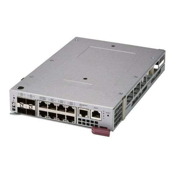
QSFP28 100-Gb Ports, one Management port and one USB port. SBM-25G-100 25-Gb Ethernet Switch Module The SBM-25G-100 is a 25-Gb Level 2 Ethernet switch module that is hot-pluggable. This module has two internal Ethernet paths to the CMM(s). The module is used to provide a connection between the Ethernet controller on the Mezzanine card and an external Ethernet device. -
Page 58: Led Indicators
Internal: Twenty (20) 25/10-Gb downlinks Internal/External Ports 4x100/406-bps QSFP28 uplinks 1 Console port LED Indicators LED indicators for the SBM-25G-100 25-Gb switch module are listed and described in Table A-8 Appendix Ports The SBM-25G-100 25-Gb switch module contains sixteen front-mounted Ports, one Management port and one USB port. -
Page 59: Mezzanine Cards
Chapter 4: Ethernet Switch Modules Mezzanine Cards For any blade module to access the InfiniBand or Omni-path switches, they need to have an installed mezzanine card in the module. Four cards (one InfiniBand, one Omni-path, two 25G) are currently available for installation in blade modules. AOC-IBH-X4ES Mezzanine EDR HCA Card Figure 4-9. -
Page 60: Aoc-Opa-Wfr Mezzanine Opa Card
8U/6U/4U SuperBlade Network System Options User’s Manual AOC-OPA-WFR Mezzanine OPA Card Figure 4-10. AOC-OPA-WFR Mezzanine OPA Card The AOC-OPA-WFR OPA mezzanine card is available for installation in blade modules in order to communicate with the SBM-OPA-C4020 OPA switch. Card features are shown below: Table 4-23. -
Page 61: Aoc-B25G-X4D Mezzanine 25G Card
Chapter 4: Ethernet Switch Modules AOC-B25G-X4D Mezzanine 25G Card Figure 4-11. AOC-B25G-X4D Mezzanine 25G Card The AOC-B25G-X4D 25G mezzanine card is available for installation in blade modules in order to communicate with the system’s switches. The card features are shown below: Table 4-24. -
Page 62: Aoc-B25G-6X4D Mezzanine 25G Card
8U/6U/4U SuperBlade Network System Options User’s Manual AOC-B25G-6X4D Mezzanine 25G Card Figure 4-12. AOC-B25G-6X4D Mezzanine 25G Card The AOC-B25G-6X4D 25G mezzanine card is available for installation in blade modules in order to communicate with the system’s switches. The card features are shown below: Table 4-25. -
Page 63: Appendix Aled Descriptions
Appendix A LED Descriptions This appendix covers LED descriptions for the blade enclosure and other module components. MBM-GEM-001 Gigabit Ethernet Module LED Descriptions MBM-GEM-001 Gigabit Ethernet module LEDs are described below in Table A-1. Table A-1. MBM-GEM-001 Gigabit Ethernet Switch LED Indicators State Description Module Initiation OK... -
Page 64: Mbm-Gem-004 Gigabit Ethernet Module Led Descriptions
8U/6U/4U SuperBlade Network System Options User’s Manual MBM-GEM-004 Gigabit Ethernet Module LED Descriptions MBM-GEM-004 Gigabit Ethernet module LEDs are described below in Table A-2. Table A-2. MBM-GEM-004 Gigabit Ethernet Switch LED Indicators State Description Module Initiation OK The MBM-GEM-004 GbE switch module is operational and has Steady On passed the POST (Power-On Self-Test) with no critical faults. -
Page 65: Mbm-Xem-001 10-Gigabit Ethernet Module Led Descriptions
MBM-XEM-001 10-Gigabit Ethernet Module LED Descriptions MBM-XEM-001 10-Gigabit Ethernet module LEDs are described below in Table A-3. Table A-3. MBM-XEM-001 10-Gigabit Ethernet Switch LED Indicators State Description Module Initiation OK The MBM-XEM-001 switch module is operational and has Steady On passed the POST (Power-On Self-Test) with no critical faults. -
Page 66: Mbm-Xem-002 10-Gigabit Ethernet Module Led Descriptions
8U/6U/4U SuperBlade Network System Options User’s Manual MBM-XEM-002 10-Gigabit Ethernet Module LED Descriptions MBM-XEM-002 10-Gigabit Ethernet module LEDs are described below in Table A-4. Table A-4. MBM-XEM-002 10-Gigabit Ethernet Switch LED Indicators State Description Module Initiation The MBM-XEM-002 switch module is operational and has Steady On OK LED passed the POST (Power-On Self-Test) with no critical faults. -
Page 67: Sbm-Xem-X8Sm 10-Gigabit Ethernet Module Led Descriptions
SBM-XEM-X8SM 10-Gigabit Ethernet Module LED Descriptions SBM-XEM-X8SM 10-Gigabit Ethernet module LEDs are described below in Table A-5. Table A-5. SBM-XEM-X8SM 10-Gigabit Ethernet Switch LED Indicators State Description Module Initiation The SBM-XEM-X8SM switch module is operational and has Steady On OK LED passed the POST (Power-On Self-Test) with no critical faults. -
Page 68: Sbm-Ibs-E3616 100-Gigabit Infiniband Module Led Descriptions
8U/6U/4U SuperBlade Network System Options User’s Manual SBM-IBS-E3616 100-Gigabit InfiniBand Module LED Descriptions SBM-IBS-E3616 100-Gigabit InfiniBand module LEDs are described below in Table A-6. Table A-6. SBM-IBS-E3616 100-Gigabit Ethernet Switch LED Indicators State Description Module Initiation The SBM-IBS-E3616 switch module is operational and has Steady On OK LED passed the POST (Power-On Self-Test) with no critical faults. - Page 69 SBM-25G-100 25-Gigabit Ethernet Module LED Descriptions SBM-25G-100 25-Gigabit Ethernet module LEDs are described below in Table A-4. Table A-7. SBM-25G-100 25-Gigabit Ethernet Switch LED Indicators State Description Module Initiation The SBM-25G-100 switch module is operational and has Steady On OK LED passed the POST (Power-On Self-Test) with no critical faults.
- Page 70 8U/6U/4U SuperBlade Network System Options User’s Manual SBM-OPA-C4020 100-Gigabit OPA Module LED Descriptions SBM-OPA-C4020 100-Gigabit OPA module LEDs are described below in Table A-6. Table A-8. SBM-OPA-C4020 100-Gigabit OPA Switch LED Indicators State Description Module Initiation OK The SBM-OPA-C4020 switch module is operational and has Steady On passed the POST (Power-On Self-Test) with no critical faults.
- Page 71 Furthermore, buyer agrees to fully indemnify, defend and hold Supermicro harmless for and against any and all claims, demands, actions, litigation, and proceedings of any kind arising out of or related to such ultra-hazardous...
Need help?
Do you have a question about the SBM-25G-100 and is the answer not in the manual?
Questions and answers