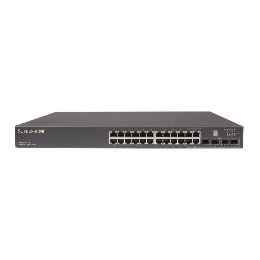
Supermicro SSE-G24-TG4 Stacking Manual
1/10g switches
Hide thumbs
Also See for SSE-G24-TG4:
- User manual (318 pages) ,
- Configuration manual (34 pages) ,
- Selection manual (1 page)
Summary of Contents for Supermicro SSE-G24-TG4
- Page 1 TACKING UIDE SUPERMICRO 1/10G Switches: SSE-G24-TG4, SSE-G48-TG4, SBM-GEM-X2C+, SBM-GEM-X3S+ Version 0.5 Copyright 2016, SUPERMICRO Computer, Inc. Confidential...
- Page 2 Please Note: For the most up-to-date version of this manual, please see our web site at www.supermicro.com. Super Micro Computer, Inc. (“Supermicro”) reserves the right to make changes to the product described in this manual at any time and without notice.
- Page 3 Revision History Date Version Author Comment 2012/12/27 Julian Chang Derived from Stacking Guide ver. 0.2 2014/3/6 Julian Chang Added MAC persistent feature. 2016/10/26 Forest Preston Edit and add SFP+ cable option Copyright 2016, SUPERMICRO Computer, Inc. Confidential...
-
Page 4: Table Of Contents
Stacking Supermicro Switches: SSE-G24-TG4, SSE-G48-TG4, SBM-GEM-X2C+, SBM-GEM-X3S+ Table of Contents Introduction ................. 1 Terminology ................. 2 Master Election ..............3 Managing Stack ..............6 Stacking Scenarios ............... 8 Creating a stack ......................... 8 Adding a switch into an running stack ..................9 ... -
Page 5: Introduction
This guide is intended to assist the system administrator who wants to build a logical switch which contains several Supermicro Intelligent Switches. The Supermicro Intelligent Switch offers a high-performance stacking solution that allows up to eight switches to be connect together so that they function as a logical unified switch, rather than as independent units. -
Page 6: Terminology
Stacking Supermicro Switches: SSE-G24-TG4, SSE-G48-TG4, SBM-GEM-X2C+, SBM-GEM-X3S+ Switch Type Maximum number of switches Maximum number of stacking ports per stack per unit SSE-G24-TG4, 2 (XG1-2 / XG2-3) SSE-G48-TG4 SBM-GEM-X2C+ 2 (XG2-3) SBM-GEM-X3S+ 2 (2 out of 3 SFP+ ports) Table 1-2: Allowable stacking port assignments... -
Page 7: Master Election
Stacking Supermicro Switches: SSE-G24-TG4, SSE-G48-TG4, SBM-GEM-X2C+, SBM-GEM-X3S+ only factor in deciding the Stack Master during the Master Election process. Backup Master (BM): A switch entity with Backup Master setting has a higher priority to be elected as the Stack Master than a Preferred Slave. - Page 8 … Configuration restoration completed successfully. … The Supermicro Intelligent Switch does have an LED illuminated on all stack members. The illumination patterns are shown below in Table 3-1. Switch Type LED pattern in Stack Master LED pattern in Stack Slave...
- Page 9 ‘8’ ‘g’ Table 3-2 LED Display for Stack ID (SSE-G24-TG4 and SSE-G48-TG4) Similarly, the SBM-GEM-X2C+ has four LEDs to display the stacking identifier. Due to the limited space available for LEDs, the stacking identifier is displayed in binary form using these four stacking LEDs. See Table 3-3.
-
Page 10: Managing Stack
IP address of the management interface must be re-configured by the CMM software. Conversely, the standalone models such SSE-G24-TG4 and SSE-G48-TG4 do not have dedicated network management interfaces. Any IP configuration will be stored in the startup configuration and the configuration file will be copied to all stack members during the initialization stage. - Page 11 -------- --------- ------ By default Supermicro switches act as standalone switches. This standalone default facilitates using 10G Ethernet ports as Extreme Ethernet ports for 10G uplinks. When stacking is enabled the stacking ports are dedicated for stacking traffic. Stacking can be enabled using the command “stack” with a switch identifier and priority. See below: SMIS# stack priority PM switchid 1 ports xg1,xg2 After enabling stacking, switch will be reloaded immediately.
-
Page 12: Stacking Scenarios
Stacking Supermicro Switches: SSE-G24-TG4, SSE-G48-TG4, SBM-GEM-X2C+, SBM-GEM-X3S+ 5. Stacking Scenarios This section will present examples of how to configuring stacking for various scenarios and will provide step-by-step guidance using the CLI command. Creating a stack Switch ID 1 (PM) -
Page 13: Adding A Switch Into An Running Stack
Stacking Supermicro Switches: SSE-G24-TG4, SSE-G48-TG4, SBM-GEM-X2C+, SBM-GEM-X3S+ SMIS# stack priority BM switchid 2 ports xg1,xg2 After enabling stacking, switch will be reloaded immediately. Do you really want to execute this command and reload the switch? [y/n] Reload Switch 2 and then configure Switch 3: SMIS# stack priority PS switchid 3 ports xg1,xg2 After enabling stacking, switch will be reloaded immediately. - Page 14 Stacking Supermicro Switches: SSE-G24-TG4, SSE-G48-TG4, SBM-GEM-X2C+, SBM-GEM-X3S+ Reload Switch 4 and then power down the specified switch. Remove the stacking cable between Switch 3 and Switch 1 and then use the same cable to connect Switch 3 and Switch 4. (See Figure 5-3).
-
Page 15: Merging Two Running Stacks Into A Single Stack
Stacking Supermicro Switches: SSE-G24-TG4, SSE-G48-TG4, SBM-GEM-X2C+, SBM-GEM-X3S+ Merging two running stacks into a single stack Switch ID 1 (PM) (Master) Switch ID 2 (PS) Switch ID 3 (PM) (Master) Switch ID 4 (PS) Figure 5-5 Before merging two separated stacks Remove the redundant stacking cable from each running stack. - Page 16 Stacking Supermicro Switches: SSE-G24-TG4, SSE-G48-TG4, SBM-GEM-X2C+, SBM-GEM-X3S+ Switch ID 1 (PM) (Master) Switch ID 2 (PS) Switch ID 3 (PM) Switch ID 4 (PS) Figure 5-7 Merging two running stacks Finally connect Switch 1 and Switch 4 with a redundant stacking link to increase the resiliency of whole stack.


Need help?
Do you have a question about the SSE-G24-TG4 and is the answer not in the manual?
Questions and answers