Supermicro SSE-G48-TG4 Quick Configuration Manual
Switch web gui
Hide thumbs
Also See for SSE-G48-TG4:
- Reference manual (985 pages) ,
- Configuration manual (85 pages) ,
- Quick configuration manual (19 pages)

Subscribe to Our Youtube Channel
Related Manuals for Supermicro SSE-G48-TG4


Summary of Contents for Supermicro SSE-G48-TG4
- Page 1 Supermicro Switch Web GUI Quick Configuration Guide Switch Web GUI Quick Configuration Guide for SSE-G48-TG4 SSE-G24-TG4 SSE-X24S SBM-GEM-X2C SBM-GEM-X2C+ SBM-GEM-X3S+ SBM-XEM-X10SM Release: 1.0a 1 / 24...
- Page 2 Supermicro Switch Web GUI Quick Configuration Guide Release: 1.0a 2 / 24...
- Page 3 Super Micro Computer, Inc. ("Supermicro") reserves the right to make changes to the product described in this manual at any time and without notice. This product, including software and documentation, is the property of Supermicro and/or its licensors, and is supplied only under a license.
-
Page 4: Table Of Contents
Supermicro Switch Web GUI Quick Configuration Guide Contents Introduction ......................... 5 Basic Configurations ....................6 Login Page ......................6 Home page ......................6 2.2.1 Page Top Links ................... 7 2.2.2 Page Top LED Display ................8 2.2.3 Left Side Tree ..................... 8 2.2.4... -
Page 5: Introduction
Supermicro Switch Web GUI Quick Configuration Guide 1 Introduction This document is designed to provide Supermicro switch users with the information required to configure the basic functionalities on the switch through its Web graphical user interface (GUI). Supermicro Switch products can be configured through Web browsers like Internet Explorer or Mozilla Firefox. -
Page 6: Basic Configurations
Supermicro Switch Web GUI Quick Configuration Guide 2 Basic Configurations 2.1 Login Page When you type the switch IP address into the browser, the following Login page appears. Fig 1: Login page Enter the User Name and Password and click on the Login button. This User Name and Password are both used for accessing the switch through the web for switch configuration. -
Page 7: Page Top Links
The Support link provides a link to the customer support group at Supermicro. The Help link provides context specific help text. This link opens a new help text page relevant to the configuration page currently being displayed. -
Page 8: Page Top Led Display
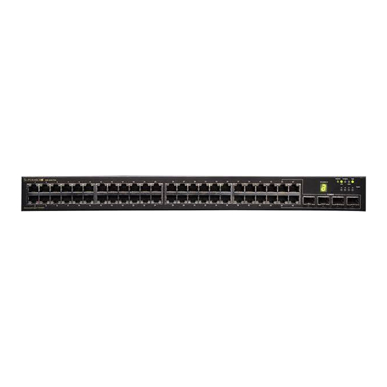
Since the number of ports is different between each of the switches, this displays a different number of ports for each type of switch. For SSE-G48-TG4, it displays 48 Gigabit Ethernet ports and four 10-Gigabit Extreme Ethernet ports. -
Page 9: Middle Configuration Link Table
Left Side Tree. The configuration links are categorized based on features of switch. 2.3 Management IP Address Note: The default management IP address for all Supermicro switch products is: 192.168.100.102. Switch Management IP Interface SSE-G24-TG4 The management IP address is configured for VLAN 1. -
Page 10: Changing The Management Ip Address & Gateway
Supermicro Switch Web GUI Quick Configuration Guide 2.3.1 Changing the Management IP Address & Gateway The management IP address and default gateway can be configured in the System Mgmt Management IP page. Fig 3: Management IP Page IP Address Mode – For a static IP addresses use the Manual mode. To get an IP address through DHCP, use the Dynamic mode. -
Page 11: User Accounts
Supermicro Switch Web GUI Quick Configuration Guide 2.4 User Accounts The default administrative user name for all Supermicro switches is ADMIN and the password for all these switches is also ADMIN. The password for this ADMIN user can be changed in the page ... -
Page 12: Interface Mtu And Jumbo Frames
MTU for 10-Gigabit ports is 16338. The Supermicro switch MTU refers only to the layer 2 payload size. Hence the MTU of 9202 means a total “in-wire” MTU of 9220 (14 bytes Ethernet Header plus 4 bytes FCS are added). -
Page 13: Interface Description
Port Manager Basic Settings page. Fig 6: Interface Description Page 2.7 Stacking The SSE-G24-TG4 and SSE-G48-TG4 switches support stacking of up to 16 switches. SBM- GEM-X2C, SBM-GEM-X2C+ support stacking of up to 8 switches. Stacking can be configured from the System Mgmt Stack Stack Settings page. - Page 14 Supermicro Switch Web GUI Quick Configuration Guide Fig 7: Stacking Page In the Ports field, list the stacking ports as comma separated without space characters. Stacking ports are named as xg1, xg2, xg3 and xg4. So if you choose ports xg1 and xg2 as stacking ports, configure the ports field as either “xg1,xg2”...
-
Page 15: Tracking Uplink Failure
Supermicro Switch Web GUI Quick Configuration Guide 4. Only the same switch models can be stacked together. For example, the SSE-G24-TG4 switch can only be stacked with other SSE-G24-TG4 switches. 5. Use the same stacking ports configuration across all the switches in stack. For example, if xg1 and xg2 is used for stacking, all switches in the stack should have the same port numbers as stacking ports. -
Page 16: Saving Configurations
Supermicro Switch Web GUI Quick Configuration Guide Enable Link Status Tracking – Choose Enable and click on the Apply button on the left panel. Configure the Group ID as 1 Configure the Upstream Interfaces as gi0/15 ... -
Page 17: Upgrading Firmware
Supermicro Switch Web GUI Quick Configuration Guide Fig 9: File Management Page 2.10 Upgrading Firmware Switch firmware can be upgraded in the System Mgmt Firmware Upgrade page. Flash Area – The default selection is Normal to upgrade firmware in normal flash area. To upgrade firmware in the fallback flash area, choose Flash Area as the Fallback. -
Page 18: Resetting To Factory Defaults
Fig 10: Firmware Upgrade Page 2.11 Resetting to Factory Defaults Supermicro switches can be reset to factory defaults in the System Mgmt System Settings page. This page has a button that you can press to allow a “Reset To Factory Defaults”. This will clear all information about switch configurations and local user accounts. - Page 19 Supermicro Switch Web GUI Quick Configuration Guide Fig 11: System Settings Page Release: 1.0a 19 / 24...
-
Page 20: Vlan Configurations
Supermicro Switch Web GUI Quick Configuration Guide 3 VLAN Configurations The SSE-G24-TG4, SSE-G48-TG4, SBM-GEM-X2C, SBM-GEM-X2C+ and SBM-GEM-X3S+ switches support 1024 static VLANs. The SSE-X24S and SBM-XEM-X10SM switches support 4K static VLANs. VLANs can be configured in Layer2 Mgmt Static VLANs page. - Page 21 Forbidden Ports – This is a list of any ports that need to forbidden from this VLAN. Note: PVID Supermicro switches associate all received untagged packets as destined for VLAN 1. This happens irrespective of the VLANs which are associated with the received ports. Therefore if you need untagged packets to be associated with a particular VLAN, it is necessary to configure a ...
-
Page 22: Link Aggregation
Supermicro Switch Web GUI Quick Configuration Guide 4 Link Aggregation Supermicro switches support both static port channel link aggregation and dynamic LACP link aggregation. Configure port channel or link aggregation as follows: Enable LA Status Create a port channel ... -
Page 23: Creating A Port Channel
Supermicro Switch Web GUI Quick Configuration Guide 4.2 Creating a Port Channel A port channel can be created in the Layer2 Mgmt Interface Settings page. Fig 14: Port Channel Page To create any port channel, enter the Port Channel ID in the page-top dialog box and click Add. -
Page 24: Configuring Port Channel Parameters
Supermicro Switch Web GUI Quick Configuration Guide Fig 15: Port Channel Ports Page For example to configure the ports gi 0/15 and gi 0/16 with static port channel 10, do the following steps. Check the check box for the port gi 0/15 and gi 0/16.
Need help?
Do you have a question about the SSE-G48-TG4 and is the answer not in the manual?
Questions and answers