Supermicro SuperBlade SBM-GEM-X2C User Manual
Superblade network modules 1/10 gbps
Hide thumbs
Also See for SuperBlade SBM-GEM-X2C:
- Reference manual (985 pages) ,
- User manual (306 pages) ,
- Configuration manual (85 pages)
Table of Contents
Advertisement
Quick Links
Advertisement
Table of Contents

Related Manuals for Supermicro SuperBlade SBM-GEM-X2C


Summary of Contents for Supermicro SuperBlade SBM-GEM-X2C
-
Page 1: Network Modules
® SuperBlade Network Modules SBM-GEM-001 Gbps SBM-GEM-X2C 1/10 Gbps Ethernet Switch Module Ethernet Switch Module SBM-GEM-002 Gbps Ethernet Pass-Through Module 4x DDR InfiniBand Module SBM-XEM-002 10Gps Ethernet Pass-Through Module User’s Manual Revison 1.0... - Page 2 Please Note: For the most up-to-date version of this manual, please see our web site at www.supermicro.com. Super Micro Computer, Inc. (“Supermicro”) reserves the right to make changes to the product described in this manual at any time and without notice. This product, including software, if any, and documentation may not, in whole or in part, be copied, photocopied, reproduced, translated or reduced to any medium or machine without prior written consent.
-
Page 3: About This Manual
About this Manual This manual is written for professional system integrators, Information Technology professionals, service personnel and technicians. It provides information for the installation and use of Supermicro's network modules. Installation and maintenance should be performed by experienced professionals only. Manual Organization Chapter 1: Introduction The first chapter provides an overview of this manual. - Page 4 Superblade Network Modules User’s Manual Notes...
-
Page 5: Table Of Contents
Installing/Removing the InfiniBand Module ..........4-2 InfiniBand Switch LEDs................4-3 Chapter 5 Ethernet Switches Modules ........5-1 5-1 SBM-GEM-001 Gigabit Ethernet Switch Module ......5-1 LED Indicators ..................5-2 Ports......................5-2 5-2 SBM-GEM-X2C 1/10 Gb Ethernet Switch Module ....... 5-3... - Page 6 Superblade Network Modules User’s Manual LED Indicators ..................5-4 Ports......................5-4 5-3 GEM-002 Gb Ethernet Pass-through Module ....... 5-5 5-4 SBM-XEM-002 1/10 Gb Ethernet Pass-through Module .... 5-6 Chapter 6 1-Gb Ethernet Switch Firmware ......6-1 6-1 SBM-GEM-001 Firmware Features and Functions .....
- Page 7 Table of Contents 7-2 Login ....................7-2 7-3 Home Page ..................7-3 Page Header Links ................. 7-4 Navigation Bar ..................7-4 Control Pane ................... 7-4 System Acknowledgement Page ............7-5 7-4 System Management Page ............. 7-6 System Information ................. 7-7 Save and Restore ...................
- Page 8 Superblade Network Modules User’s Manual Basic Settings ..................7-41 Classmap ................... 7-42 Policymap................... 7-43 COSQ Algorithm ................7-44 Cosq Traffic Class ................7-45 7-5 Layer2 Management Page ............7-46 Port Manager ..................7-47 Basic Settings ..................7-48 Port Monitoring................... 7-49 Traffic Class ..................
- Page 9 Table of Contents Interface Settings ................7-81 Port Channel Settings ................ 7-82 Port Settings..................7-84 Port State Info ..................7-86 Load Balancing .................. 7-87 802.1x ....................7-87 Basic Settings ..................7-88 Port Settings..................7-89 Timers ....................7-91 Local AS..................... 7-93 Radius Settings ..................
- Page 10 Superblade Network Modules User’s Manual Summarization ................. 7-125 RIPng ....................7-126 RIP6 Interface .................. 7-126 Filters ....................7-128 OSPF ....................7-129 Basic Settings .................. 7-129 Area....................7-131 Interface ................... 7-132 Virtual Interface ................7-134 Neighbor................... 7-135 RRD Route..................7-136 Aggregation..................7-137 AsExtAggregation ................
- Page 11 Table of Contents Timer ....................7-167 Interface Configuration..............7-168 Router Ports ..................7-170 Group Information ................7-171 Dynamic Multicast................7-172 Dynamic Multicast ................7-172 Port Settings..................7-173 IGMP....................7-174 Basic Settings .................. 7-175 Interface Configuration..............7-176 Group Information ................7-177 Source Information................
- Page 12 Superblade Network Modules User’s Manual Capabilities..................7-204 FDB Entries..................7-205 RSTP ....................7-206 Information ..................7-206 Port Statistics ................... 7-207 MSTP ....................7-207 Information ..................7-208 CIST Port Statistics ................7-209 MSTI Port Statistics................7-210 LA......................7-211 PortLACP Stats ................7-211 Neighbor Stats..................
- Page 13 Table of Contents RMON ....................7-233 TACACS+.................... 7-234 SNMP....................7-235 Appendix A HCA Mezzanine Cards ...........A-1 A-1 Safety Guidelines ................A-1 ESD Safety Guidelines ................A-1 General Safety Guidelines ..............A-1 A-2 Mezzanine HCA Cards ..............A-2 A-3 Installation ..................A-4 Installation Location ................A-5 Card Installation ..................A-5 Appendix B LED Descriptions ............B-1 B-1 Gigabit Ethernet Module LED Descriptions...
- Page 14 Superblade Network Modules User’s Manual Notes...
- Page 15 Figure 3-8. Setting Hardware Information ............3-11 Figure 4-1. InfiniBand Module ................4-1 Figure 5-1. SBM-GEM-001 Gigabit Ethernet Switch Module ......5-1 Figure 5-2. SBM-GEM-X2C 1/10 Gigabit Ethernet Switch Module Ports and Indicators ..................5-3 Figure 5-3. SBM-GEM-001 Gigabit Pass-through Module........ 5-5 Figure 5-4.
- Page 16 Superblade Network Modules User’s Manual Figure 7-2. Home Page..................7-3 Figure 7-3. System Acknowledgement Page ............ 7-5 Figure 7-4. System Management Page ............7-6 Figure 7-5. System Information Page ............... 7-7 Figure 7-6. Save Configuration Page..............7-9 Figure 7-7. Restore Configuration Page ............7-10 Figure 7-8.
- Page 17 List of Figures Figure 7-42. Rate Limiting Page ..............7-52 Figure 7-43. VLAN Basic Settings Page ............7-53 Figure 7-44. VLAN Port Settings Page ............7-55 Figure 7-45. Static VLAN Configuration Page..........7-56 Figure 7-46. VLAN Protocol Group Settings Page.......... 7-57 Figure 7-47.
- Page 18 Superblade Network Modules User’s Manual Figure 7-82. IPv4 Interface Settings Page ............ 7-104 Figure 7-83. IP Route Configuration Page ............ 7-105 Figure 7-84. LoopBack Basic Settings Page..........7-106 Figure 7-85. IP6 Route Configuration Page ..........7-107 Figure 7-86. IPv6 Interface Settings Page ............ 7-108 Figure 7-87.
- Page 19 List of Figures Figure 7-122. RRD OSPF Configuration Page ..........7-156 Figure 7-123. RRD6 Filter Configuration Page ..........7-158 Figure 7-124. RRD6 OSPFv3 Configuration Page........7-159 Figure 7-125. RRD RIPv6 Configuration Page ..........7-160 Figure 7-126. VRRP Basic Settings Page............. 7-161 Figure 7-127.
- Page 20 Superblade Network Modules User’s Manual Figure 7-162. VLAN Counter Statistics Page..........7-203 Figure 7-163. VLAN Capabilities Page ............7-204 Figure 7-164. VLAN FDB Entries Page............7-205 Figure 7-165. RSTP Information Page............7-206 Figure 7-166. RSTP Port Statistics Page............7-207 Figure 7-167. MSTP Information Page ............7-208 Figure 7-168.
- Page 21 Table 5-2. GEM-001 Gigabit Ethernet Switch Module Features ....... 5-2 Table 5-3. SBM-GEM-001 Gigabit Ethernet Switch Module Ports....5-2 Table 5-4. SBM-GEM-X2C 1/10 Gigabit Ethernet Switch Module Interface ..5-3 Table 5-5. SBM-GEM-X2C 1/10 Gigabit Ethernet Switch Module Features ..5-4 Table 5-6.
- Page 22 Superblade Network Modules User’s Manual Table 7-16. TACACS+ Server Configuration Page Parameters ..... 7-31 Table 7-17. TACACS+ Global Settings Page Parameters......7-32 Table 7-18. Syslog Configuration Page Parameters........7-33 Table 7-19. Syslog Configuration Page Parameters........7-34 Table 7-20. IP Authorized Manager Page Parameters ........7-35 Table 7-21.
- Page 23 List of Tables Table 7-55. IMAC Session Info Page Parameters .......... 7-96 Table 7-56. L2 Unicast Filter Configuration Page Parameters......7-97 Table 7-57. L2 Multicast Filter Configuration Page Parameters ..... 7-99 Table 7-58. Forward Ports Configuration Page Parameters ......7-100 Table 7-59.
- Page 24 Superblade Network Modules User’s Manual Table 7-94. BGP Filter Configuration Page Parameters ....... 7-151 Table 7-95. BGP Route Aggregation Configuration Page Parameters ..7-152 Table 7-96. RRD Basic Settings Page Parameters ........7-154 Table 7-97. RRD BGP Configuration Page Parameters ....... 7-155 Table 7-98.
-
Page 25: Chapter 1 Introduction
Introduction Overview The Superblade Network Modules User’s Manual contains information on all network modules used for the Supermicro SuperBlade system. This incorporates information on the InfiniBand module, all switch modules and all pass-through modules. Product Checklist of Typical Components All modules are shipped alone or with a SuperBlade enclosure when ordered. Aside from packaging, no cables or cords are included. -
Page 26: Contacting Supermicro
Address: Super Micro Computer, Inc. 980 Rock Ave. San Jose, CA 95131 U.S.A. Tel: +1 (408) 503-8000 Fax: +1 (408) 503-8008 marketing@supermicro.com (General Information) Email: support@supermicro.com (Technical Support) Web Site: www.supermicro.com Europe Address: Super Micro Computer B.V. Het Sterrenbeeld 28, 5215 ML ‘s-Hertogenbosch, The Netherlands... -
Page 27: Chapter 2 System Safety
Chapter 2 System Safety System safety precautions and information is included in this chapter. Please review this information before installing or using your Supermicro equipment. Electrical Safety Precautions Basic electrical safety precautions should be followed to protect yourself from harm and the SuperBlade from damage: •... -
Page 28: General Safety Precautions
Superblade Network Modules User’s Manual General Safety Precautions Follow these rules to ensure general safety: • Keep the area around the SuperBlade clean and free of clutter. • Place the blade module cover and any system components that have been removed away from the system or on a table so that they won't accidentally be stepped on. -
Page 29: Chapter 3 Setup And Installation
This chapter covers the setup and installation of the SuperBladeSuperBlade Ethernet switch modules. SuperMicro has two different Gigabit Ethernet switch modules for its SuperBlade system. The first is the SBM-GEM-001 Gigabit Ethernet switch module with ten external 1-Gbps Ethernet uplinks. The second SBM-GEM-X2C 1/10 Gigabit Ethernet switch module is a 1-Gbps Ethernet switch with three external 10-Gbps uplink and two external 1-Gbps Ethernet uplink ports. -
Page 30: Figure 3-1. Blade Enclosure With Gbps Switch Modules Installed
Superblade Network Modules User’s Manual Figure 3-1. Blade Enclosure with Gbps Switch Modules Installed SBM-GEM-001 Switch Modules InfiniBand Pass-Through Module... -
Page 31: Removing A Switch Module
Chapter 3: Setup and Installation Figure 3-2. Blade Enclosure with 1/10 Gbps Switch Modules Installed SBM-GEM-X2C Switch Modules SBM-XEM-002 Pass-Through Module 5. Push the release handle to the closed position. NOTE: After the module has been installed and the handle locked, it will turn on and a POST test will run to verify it is working properly. -
Page 32: Configuring The Switch Module
Superblade Network Modules User’s Manual Configuring the Switch Module Figure 3-3. Configuring the Switch Module A Gigabit Ethernet switch module can be configured using two methods (as shown in Figure 3-3). You may configure it: • Through the web-based management utility or IPMI (via the CMM module) •... -
Page 33: Web-Based Management Utility/Ipmi
Chapter 3: Setup and Installation Web-based Management Utility/IPMI Using the Web-based Management Utility or IPMI is the most user-friendly method of configuring the switch module. You can access the configuration menu either through the management utility or by a network connection. See either Chapter 6 Chapter 7... -
Page 34: Figure 3-5. Ipmi Blade System Screen
Superblade Network Modules User’s Manual a. Type in your Username in the U box. SERNAME b. Type in your Password in the P box and click on L ASSWORD OGIN NOTE: The default username and the default password are both ADMIN. The Default IP address is 192.168.100.102. -
Page 35: Address Defaults
Chapter 3: Setup and Installation Figure 3-6. Gigabit Switch Panel Address Defaults The following are the default addresses that are initially set. Afterwards, you can change these values within the program. Table 3-1. SBM-GEM-001 Switch Module Address Default Settings Address Default Setting Default IP Address 192.168.100.102... -
Page 36: Command Line
Superblade Network Modules User’s Manual Command Line Configuring the switch can be done using a command line via telnet or by using the serial console interface. Accessing CLI through Telnet: To access command line via telnet, follow the below steps. 1. -
Page 37: 1/10 Gigabit Ethernet Switch Firmware
Chapter 3: Setup and Installation 1/10 Gigabit Ethernet Switch Firmware The firmware for the 1/10 Gigabit Ethernet switch module resides on a chip on the PCB. The switch has internal flash memory in two areas to hold two firmware images. The flash area used for the normal firmware image is referred to as the normal area. -
Page 38: Figure 3-7. Displayed Text For Rebooting
Superblade Network Modules User’s Manual Booting using a Fallback Firmware Image: Use the procedure below to boot using a fallback firmware image. 1. Reboot the switch by power cycling the switch power. 2. During reboot, press any key when it displays the below text (as shown in Figure 3-7). -
Page 39: Figure 3-8. Setting Hardware Information
Chapter 3: Setup and Installation NOTE: The numbers in the Product Type entry change depending upon the switch you are using. 3. Once the boot sequence is interrupted, it will display menu options as shown in Figure 3-7. Use the "H" option to set hardware information by typing the character H. This will display the hardware information that can be changed as shown in Figure 3-8. -
Page 40: Firmware Failure Recovery Steps
Superblade Network Modules User’s Manual 8. In case you wish to later move back to a normal image, repeat the above the steps with one difference for step 4, where you should use the command rflag=0 instead of rflag=1 to boot with a normal firmware image. Upgrading Fallback Firmware using TFTP: To upgrade fallback firmware using TFTP, use the procedure below. - Page 41 For example gateway=192.168.2.100 8. Configure the firmware image file name using the below command: ramdiskname=<filename> For example ramdiskname= SBM-GEM-X2C-v5.2.10.bin 9. Type Save to save the hardware information. 10. Type Exit to exit the hardware information menu. 11. Type F to download the firmware image. In this case it will download to the normal image area.
- Page 42 Superblade Network Modules User’s Manual Notes...
-
Page 43: Chapter 4 Infiniband Module
Chapter 4 InfiniBand Module Overview InfiniBand is a switch-based, point-to-point bidirectional serial link network communications architecture. The main function of the SuperBlade InifiniBand switch module is to provide high-speed interconnectivity among the blade modules and external peripherals. This is a hot-pluggable module that must be installed in a double-wide bay at the lower right of the enclosure. -
Page 44: Installing/Removing The Infiniband Module
Superblade Network Modules User’s Manual Table 4-2. InfiniBand Module Features Feature Description Internal: 10 4X DDR copper ports (capable of 14) / External: 10 4X DDR Internal/External Ports copper ports 4X DDR (20 Gbps) non-blocking architecture for 960 Gbps total bandwidth Bandwidth (24-port) Latency... -
Page 45: Infiniband Switch Leds
Chapter 4: InfiniBand Module InfiniBand Switch LEDs InfiniBand switch LEDs are listed and described in Table B-4 Appendix Configuring the InfiniBand Module Maintenance and configuration of the InfiniBand module within a Windows OS is performed with Mellanox's® WinIB™ software package. WinIB allows you to upgrade the firmware and monitor temperature, voltages, port utilization and other switch parameters. - Page 46 Superblade Network Modules User’s Manual Notes...
-
Page 47: Chapter 5 Ethernet Switches Modules
Chapter 5 Ethernet Switches Modules Your SuperBlade enclosure can include either of two models of Ethernet switch modules or two models of Ethernet pass-through modules installed in it. The Ethernet switch modules and SBM-GEM-002 Gigabit pass-through module can only be installed in the upper and/or lower left module bays, whereas the SBM-XEM-002 10-Gigabit pass-through module must be installed in a double-wide slot in the enclosure instead of an InfiniBand Module. -
Page 48: Led Indicators
Superblade Network Modules User’s Manual Table 5-2. GEM-001 Gigabit Ethernet Switch Module Features Feature Description Chipset Broadcom BCM5345M Internal: Fourteen 1 Gbps downlink ports / External: Ten 1 Gbps RJ45 Internal/External Ports uplink ports Bandwidth 24 Gbps non-blocking Trunking Link aggregation support Jumbo Frame Support Up to 9 kb Remote Management... -
Page 49: Sbm-Gem-X2C 1/10 Gb Ethernet Switch Module
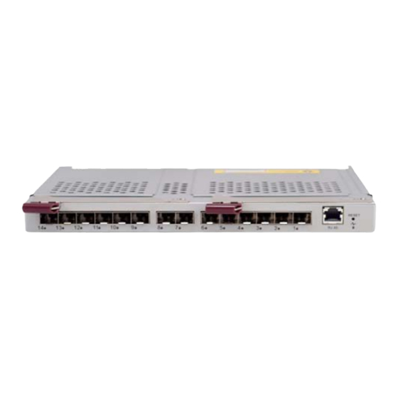
Chapter 5: Ethernet Switches Modules SBM-GEM-X2C 1/10 Gb Ethernet Switch Module The SBM-GEM-X2C 1/10 Gigabit Ethernet switch module is a layer 2/3 Ethernet switch. It includes three 10-Gb/s uplink ports (two CX4 and one SPF+), two 1-Gb/s uplink RJ-45 uplink ports and fourteen 1-Gb/s downlink ports for the SuperBlade's LAN interfaces. -
Page 50: Led Indicators
Section 3-3: 1/10 Gigabit Ethernet Switch Firmware on Operating System page 3-9 for details) LED Indicators LED indicators for the SBM-GEM-X2C 1/10 Gigabit Ethernet switch module are listed and described in Table B-2 Appendix Ports The SBM-GEM-X2C 1/10 Gigabit Ethernet switch module contains several... -
Page 51: Gb Ethernet Pass-Through Module
Chapter 5: Ethernet Switches Modules GEM-002 Gb Ethernet Pass-through Module The SBM-GEM-002 Gigabit pass-through module is a non-configurable pass through module that includes fourteen (fourteen) 1-Gb/s uplink (RJ45) ports and fourteen 1-Gb/s downlink ports for the SuperBlade's LAN interfaces. This Ethernet module has two internal Ethernet paths to the CMM(s). -
Page 52: Sbm-Xem-002 1/10 Gb Ethernet Pass-Through Module
10-GbE firmware loaded on it. See Appendix A for details on the AOC-IBH-003 card. Unlike the SBM-GEM-001 or SBM-GEM-X2C Ethernet switch modules this is a pass-through module, and just like the GEM-002 Gb Ethernet Pass-through Module model described above, it is not configurable. -
Page 53: Figure 5-4. Sbm-Xem-002 10-Gigabit Pass-Through Module
Chapter 5: Ethernet Switches Modules Figure 5-4. SBM-XEM-002 10-Gigabit Pass-through Module Table 5-9. SBM-XEM-002 10-Gigabit Pass-through Module Interface Item Description Module Release Handles 10-Gbp/s Uplink SFP+ Ports RJ-45 Ethernet Port (Reserved for Future Use) “Initiation OK” LED (Reserved for Future Use) Reset Button (Reserved for Future Use) Table 5-10. - Page 54 Superblade Network Modules User’s Manual Notes...
-
Page 55: Chapter 6 1-Gb Ethernet Switch Firmware
Chapter 6 1-Gb Ethernet Switch Firmware The firmware configuration system for the SBM-GEM-001 Gigabit Ethernet switch module is covered in this chapter. SBM-GEM-001 Firmware Features and Functions Table 6-1 provides a summary of features and functions for the Gigabit Ethernet switch module firmware. -
Page 56: Figure 6-1. Switch Status Screen
Superblade Network Modules User’s Manual To configure the switch, select the switch you want in the S screen in the WITCH TATUS Web-based Management Utility. See the Web-based Management Utility User’s Manual for details. screen will appear (Figure 6-1) in your browser. WITCH TATUS Figure 6-1. -
Page 57: Port Status
Chapter 6: 1-Gb Ethernet Switch Firmware Port Status The P screen provides a status overview of the switch’s 24 ports. As shown TATUS Figure 6-3, it includes link, speed, duplex, flow control, jumbo frame and PVID. In this screen click on P on the left menu bar. -
Page 58: Port Vlan Id (Pvid)
Superblade Network Modules User’s Manual Port VLAN ID (PVID) The PVID is used in a port-based VLAN to allow assigning a port to belong to a VLAN. A VLAN can then be configured to be a group of member ports. This switch is an 802.1q tag-aware switch. -
Page 59: Figure 6-5. Port Configuration Screen
Chapter 6: 1-Gb Ethernet Switch Firmware Figure 6-5. Port Configuration Screen Table 6-2. Port Configuration Screen Controls Control Description Port Specifies the port number to control. Admin Enables or disables the port. Enables or disables auto-negotiation. When auto-negotiation is enabled, the port negotiates with the link partner and works out speed, duplex operation, and flow Auto Negotiation control. -
Page 60: Statistics
Superblade Network Modules User’s Manual Statistics The S screen displays the total number of packets transmitted or received on TATISTICS each port as shown in Figure 6-6. Click on the R button to retrieve the current EFRESH count and update the screen. Click on the C button to reset the count to LEAR OUNTERS... -
Page 61: Figure 6-7. Port Statistics Screen
Chapter 6: 1-Gb Ethernet Switch Firmware Figure 6-7. Port Statistics Screen Table 6-3. Port Statistics Screen Controls Control Description Displays traffic information on outgoing frames. Octets Indicates total octets transmitted. UnicastPkts This indicates transmitted unicast packets. NonUnicastPkts This indicates transmitted non-unicast packets. Discards This indicates discarded packets. - Page 62 Superblade Network Modules User’s Manual Table 6-3. Port Statistics Screen Controls (Continued) Control Description Indicates undersize/fragment/FCS error/oversized errors with good FCS Errors packets. Displays traffic information by packet type, type of error and frame size Summary range. Indicates events in which packets are dropped due to a lack of resources. DropEvents This includes events where the receiving shared buffer is full, and events when a transmission failure is due to a late collision.
-
Page 63: Vlan
Chapter 6: 1-Gb Ethernet Switch Firmware Table 6-3. Port Statistics Screen Controls (Continued) Control Description 1519-9216 Bytes Rx indicates received packets with a packet length that is between (includes) Pkts 1519 ~ 9216 bytes. 1519-9216 Bytes Tx indicates transmitted packets with a packet length that is between Pkts (includes) 1519 ~ 9216 bytes. - Page 64 Superblade Network Modules User’s Manual of the VLAN, the frame is forwarded to the destination port. If the incoming frame is not tagged with VLAN information, the ingress port will use PVID as the VLAN ID. If the destination port is not in the same VLAN, the frame is dropped. The switch is initially configured to have one VLAN and its VID is 1.
-
Page 65: Configuring A Static Vlan
Chapter 6: 1-Gb Ethernet Switch Firmware Configuring a Static VLAN The switch currently supports static VLANs only. To configure the VLAN, click on the VLAN folder at the left-hand side bar. The IEEE802.1Q VLAN screen should appear as shown in Figure 6-8. -
Page 66: Trunking
Trunking aggregates multiple physical ports link into a single trunk to provide a single logical high-speed pipeline link. This is useful for switch-to-switch, switch-to-server and switch-to-router applications. The SuperMicro Gigabit Ethernet switch supports static type link aggregations. It uses a distribution algorithm to balance traffic between trunk members. -
Page 67: Figure 6-11. Trunking Screen
Chapter 6: 1-Gb Ethernet Switch Firmware transmitted must not be out of order. The switch performs load balancing based on a distribution algorithm that used the following information to assign conversation to ports: • MAC source address • MAC destination address •... -
Page 68: Mirroring
Superblade Network Modules User’s Manual Mirroring The switch supports port mirroring. A copy of the egress (transmit) data and the ingress (receive) data of the mirrored (monitored) port is sent to the mirroring (snooping) port. A user can attach a monitoring device to the mirroring port, such as a sniffer or an RMON probe to view the traffic at the mirrored port. -
Page 69: Quality Of Service
Chapter 6: 1-Gb Ethernet Switch Firmware Quality of Service Quality of Service (QoS) helps a network user to reserve a guaranteed bandwidth for some critical application functions that require a high bandwidth and high priority. Applications such as video, audio streaming, VoIP and video conferencing must have a certain amount of bandwidth to maintain their operation correctly. -
Page 70: Figure 6-13. Qos Setting Screen
Superblade Network Modules User’s Manual Figure 6-13. QoS Setting Screen Table 6-5. QoS Setting Screen Controls Control Description This specifies one of the two scheduling methods (Strict and Weighted Scheduling Method Round-Robin) for the queues. Queue [0:3] prioritizes the four queues. Queue 0 is the lowest priority queue and Queue [0:3] queue 3 is the highest priority queue. -
Page 71: Rate Control
Chapter 6: 1-Gb Ethernet Switch Firmware Rate Control The switch supports per-port rate control. When the data rate of the incoming frame for a particular port exceeds a selected rate, the excess frame traffic is subject to packet drops or flow control, depending on the per-port flow control configuration in the P folder. -
Page 72: L2 Management
Superblade Network Modules User’s Manual To configure storm control, click S link in the R TORM ONTROL IMIT AND TORM screen (Figure 6-14). The S screen appears as shown in ONTROL TORM ONTROL Figure 6-15. Figure 6-15. Storm Control Screen Table 6-6. -
Page 73: Figure 6-16. L2 Management Screen
Chapter 6: 1-Gb Ethernet Switch Firmware Figure 6-16. L2 Management Screen To remove the specified static MAC address from the table, click the D link for that ELETE MAC address as shown in Figure 6-17 when there are static entries in the table. To search for a MAC address to see if it exists in the table or not, enter the MAC and VID, then click on L button. -
Page 74: 6-10 Spanning Tree
Superblade Network Modules User’s Manual 6-10 Spanning Tree The Spanning Tree Protocol (STP) helps to detect and prevents loops from occurring on a switched or bridged network. When multiple paths exist on a network, STP will configure the network to use the most efficient path between network devices. All other paths are forced into a blocked standby state. -
Page 75: Port Transition State
Chapter 6: 1-Gb Ethernet Switch Firmware root switch will set a Topology Change flag in its normal BPDUs. This flag is propagated to all other switches to instruct them to rapidly age out their forwarding table entries. Port Transition State When a device is connected to an RTSP or STP enabled switch port for the first time, it will not immediately start to forward data. -
Page 76: Figure 6-18. Rapid Spanning Tree Screen
Superblade Network Modules User’s Manual Figure 6-18. Rapid Spanning Tree Screen The RSTP S allows the user to control RSTP parameters from the WITCH ETTINGS bridge point-of-view. R shows status of the root bridge. B TATUS RIDGE ETTING shows the current bridge setup. To turn on the Rapid Spanning Tree Protocol (RSTP), check on the E RSTP dialog NABLE... -
Page 77: Root Status
Chapter 6: 1-Gb Ethernet Switch Firmware Root Status The settings for R are shown below: TATUS • Designated Root Bridge – The bridge identifier of the root of the spanning tree is determined by the RSTP protocol as executed by this node. The bridge identifier value is used as the Root Identifier parameter in all configuration Bridge PDUs originated by this node. -
Page 78: Rstp Port Settings
Superblade Network Modules User’s Manual RSTP Port Settings These settings control and monitor the port-based spanning tree status. • Participate – This specifies if the RSTP is enabled or not for the selected port. • Cost – Displays the cost of this port. “Cost” means the contribution of this port to the path cost of paths towards the spanning tree root which include this port. -
Page 79: 6-11 Ieee 802.1X
Chapter 6: 1-Gb Ethernet Switch Firmware 6-11 IEEE 802.1x IEEE 802.1x is a client-server based access control and authentication protocol that restricts unauthorized user devices from connecting to the LAN through publicly accessible ports. This port-based access control is accomplished by using a RADIUS server that is connected to a gigabit switch management port to authenticate client users trying to access a network through the switch. -
Page 80: 802.1X Configuration
Superblade Network Modules User’s Manual 802.1x Configuration Figure 6-20. 802.1x Configuration Screen To configure 802.1x port based access control, click on the 802.1 folder in the left-hand side bar. The 802.1 configuration should display as shown in Figure 6-20. Check the dialog box to enable 802.1x port based access control. -
Page 81: 6-12 Igmp Snooping
Chapter 6: 1-Gb Ethernet Switch Firmware • Authorization – This displays the authentication status of an enabled port. It includes the following status: • In Progress – This indicates that the authentication is still in progress. Traffic is not forwarded before authentication is verified. •... -
Page 82: Figure 6-21. Igmp Snooping Screen
Superblade Network Modules User’s Manual Figure 6-21. IGMP Snooping Screen... -
Page 83: 6-13 Snmp
Chapter 6: 1-Gb Ethernet Switch Firmware Table 6-8. IGMP Snooping Screen Controls Control Description This allows tuning for the expected packet loss on a subnet. If a subnet is expected to be lossy, the Robustness Variable may be increased. IGMP is robust Robustness Variable to (Robustness Variable-1) packet losses. -
Page 84: Uplink Failure Tracking (Ulft)
Superblade Network Modules User’s Manual 6-14 UpLink Failure Tracking (ULFT) Uplink Failure Tracking (ULFT) feature is provided to support network adapter Teaming (Windows Systems) or Channel Bonding (Linux Systems) on SuperBlade servers. Installing two GbE switch modules can have additional connectivity to allow increased network bandwidth, redundancy, and/or fault tolerance. -
Page 85: Chapter 7 10-Gb Ethernet Switch Firmware
Chapter 6: 1-Gb Ethernet Switch Firmware Note that ULTF will only drop an internal link from the blade to the switch if all of the (external) uplinks defined for that blade have failed (or been disabled) on that switch. As long as one or more of uplinks on a particular switch (that have been defined for a particular downlink) is active, the blade and switch will keep the internal link active. - Page 86 Superblade Network Modules User’s Manual Notes...
-
Page 87: Overview
10-Gb Ethernet switch firmware and its controls. Overview The Supermicro switch utility for the SBM-GEM-X2C 1/10 Gigabit Ethernet switch module provides a web-based interface for managing layer2 and layer3 switching at wire speed for constructing a switched/routed network. This interface provides both a bridging functionality and advanced features such as link aggregation, Dynamic VLAN/ Dynamic Multicast, IGMP Snooping and Network Access Control. -
Page 88: Login
Figure 7-1. Login Page The initial login page (Figure 7-1) is used to login to the Supermicro Switch web-based management utility for the SBM-GEM-001. To login, enter your user name and password in the fields provided and press the L button. -
Page 89: Home Page
(Figure 7-2) contains links and menus for going to all other control pages in the Supermicro Switch web-based interface utility. A list of controls for this page is shown in Table 7-1. The basic page structure of the H page is duplicated for all subsequent sub-pages of the Supermicro Switch web-based interface utility. -
Page 90: Page Header Links
P links: EADER • Support – Click this link to get technical support for Supermicro Products. • Help – Click on this link to open a help page that covers all the items on the page being viewed. -
Page 91: System Acknowledgement Page
Chapter 7: 10-Gb Ethernet Switch Firmware System Acknowledgement Page Figure 7-3. System Acknowledgement Page The S link in the home page brings up the S YSTEM CKNOWLEDGEMENT YSTEM page (Figure 7-3), which displays acknowledgement information for CKNOWLEDGEMENT the various open source (OpenSSL (Secure Socket Layer), OpenSSH (Secure Shell), etc) software used in the 1/10 Gigabit Ethernet switch module web-based management utility. -
Page 92: System Management Page
Superblade Network Modules User’s Manual System Management Page Figure 7-4. System Management Page The S page (Figure 7-4) contains the following links: YSTEM ANAGEMENT • System Information • Save and Restore • System Settings • SNMP • RMON • TACACS+ Server •... -
Page 93: System Information
Chapter 7: 10-Gb Ethernet Switch Firmware System Information Figure 7-5. System Information Page Clicking the S link brings up the S page YSTEM NFORMATION YSTEM NFORMATION (Figure 7-5). You can modify the name and description of the switch on this page by entering the necessary details. - Page 94 Superblade Network Modules User’s Manual Table 7-2. System Information Page Parameters (Continued) Parameter Description The Login Authentication Mode (either Local or Remote login) can be Login Authentication Mode configured here. Configuration Save Status The Configuration Save Status is shown here. Remote Save Status The Remote Save Status is shown here.
-
Page 95: Save And Restore
Chapter 7: 10-Gb Ethernet Switch Firmware Save and Restore The S link of the S page allows you to configure AVE AND ESTORE YSTEM NFORMATION options through the following control tabs: AVE AND ESTORE • Save • Restore • Erase Save Figure 7-6. -
Page 96: Restore
Superblade Network Modules User’s Manual Restore Figure 7-7. Restore Configuration Page Clicking on the R tab brings up the R page (Figure 7-7). ESTORE ESTORE ONFIGURATION This page allows you to restore the configuration to ISS from the Flash. -
Page 97: Erase
Chapter 7: 10-Gb Ethernet Switch Firmware Erase Figure 7-8. Erase Configuration Page Clicking on the E tab brings up the E page (Figure 7-8). This RASE RASE ONFIGURATION page allows you to erase a saved configuration from NVRAM, Flash or a specified saved file. -
Page 98: System Settings
Superblade Network Modules User’s Manual System Settings Figure 7-9. System Settings Page Clicking on the S link brings up the S page (Figure 7-9). YSTEM ETTINGS YSTEM ETTINGS You can either choose to obtain the IP address through DHCP or decide to configure it manually. -
Page 99: Snmp
Chapter 7: 10-Gb Ethernet Switch Firmware Table 7-3. System Settings Page Parameters (Continued) Parameter Description Switch Base MAC Address Specifies the switch’s Base MAC Address. SNMP Engine ID Specifies the SNMP Engine ID used. PIM Mode Specifies the PIM Mode used. Snoop Forward Mode Specifies the Snoop Forward Mode used. -
Page 100: Community
Superblade Network Modules User’s Manual The A link allows you to configure SNMP Agent related configuration through the GENT following control tabs: • Community • Group • Group Access • View • Target Address • Target Parameter • User • Trap Manager By default, the C tab is loaded. -
Page 101: Figure 7-11. Snmp Community Settings Page
Chapter 7: 10-Gb Ethernet Switch Firmware Community Figure 7-11. SNMP Community Settings Page Clicking on the C tab brings up the SNMP C page OMMUNITY OMMUNITY ETTINGS (Figure 7-11). This page displays the access permissions of the already configured SNMP Managers. This page allows you to configure new managers to the table and delete existing managers from the same. -
Page 102: Figure 7-12. Snmp Group Settings Page
Superblade Network Modules User’s Manual Table 7-4. SNMP Community Settings Page Parameters (Continued) Parameter Description Transport Tag This field allows you to set the Transport Tag setting. This drop-down list box allows you to set the Storage Type, which can be Storage Type configured as Volatile or Non-Volatile. -
Page 103: Figure 7-13. Snmp Group Access Settings Page
Chapter 7: 10-Gb Ethernet Switch Firmware Table 7-5. SNMP Group Settings Page Parameters Parameter Description Security Model This drop-down list box allows you to set the Security Model used. Security Name This field allows you to set the Security Name setting. Group Name This field allows you to set the Group Name setting. -
Page 104: View
Superblade Network Modules User’s Manual Table 7-6 lists the parameters found on this page. Table 7-6. SNMP Group Access Settings Page Parameters Parameter Description Group Name This field allows you to set the Group Name setting. Security Model This drop-down list box allows you to set the Security Model used. Security Level This drop-down list box allows you to set the Security Level used. -
Page 105: Table 7-7. Snmp Viewtree Settings Page Parameters
Chapter 7: 10-Gb Ethernet Switch Firmware Clicking on the V tab brings up the SNMP V page (Figure 7-14). ETTINGS The S , when combined with the corresponding instance of M , defines a family of view subtrees. V is the name for a family of view subtrees. It also displays the S of the V table. -
Page 106: Target Address
Superblade Network Modules User’s Manual Target Address Figure 7-15. SNMP Target Address Settings Page Clicking on the T tab brings up the SNMP T ARGET DDRESS ARGET DDRESS ETTINGS page (Figure 7-15). Table 7-8 lists the parameters found on this page. Table 7-8. -
Page 107: Target Parameter
Chapter 7: 10-Gb Ethernet Switch Firmware Target Parameter Figure 7-16. SNMP Target Parameter Settings Page Clicking on the T tab brings up the SNMP T ARGET ARAMETER ARGET ARAMETER page (Figure 7-16). The Target Param specifies SNMP target information to ETTINGS be used in the generation of SNMP messages. -
Page 108: User
Superblade Network Modules User’s Manual Table 7-9. SNMP Target Parameter Settings Page Parameters (Continued) Parameter Description This drop-down list box allows you to set the Security Level used when Security Level generating SNMP messages. This drop-down list box allows you to set the Storage Type, which can be Storage Type configured as Volatile or Non-Volatile. -
Page 109: Table 7-10. Snmp Security Settings Page Parameters
Chapter 7: 10-Gb Ethernet Switch Firmware Table 7-10. SNMP Security Settings Page Parameters Parameter Description This field allows you to set the User Name, which is the (User-based User Name Security) Model dependent security ID. This drop-down list box allows you to set the Authentication Protocol, Authentication Protocol which is the type of authentication protocol used for authentication. -
Page 110: Trap Manager
Superblade Network Modules User’s Manual Trap Manager Figure 7-18. SNMP Trap Settings Page Clicking on the T tab brings up the SNMP T page ANAGER ETTINGS (Figure 7-18). An entry in the table selects a set of management targets, which must receive notifications. -
Page 111: Rmon
Chapter 7: 10-Gb Ethernet Switch Firmware RMON The RMON link allows you to configure RMON parameters. The following control tabs are available for configuration: • Basic Settings • Alarms • Ethernet Statistics • Events • History By default, the B tab is loaded. -
Page 112: Alarms
Superblade Network Modules User’s Manual Alarms Figure 7-20. RMON Alarm Configuration Page Clicking on the A tab brings up the RMON A page LARMS LARM ONFIGURATION (Figure 7-20). Table 7-12 lists the parameters found on this page. Table 7-12. RMON Alarm Configuration Page Parameters Parameter Description Index... -
Page 113: Ethernet Statistics
Chapter 7: 10-Gb Ethernet Switch Firmware Table 7-12. RMON Alarm Configuration Page Parameters (Continued) Parameter Description Specifies a threshold for the sampled statistic. When the current sampled value is less than or equal to this threshold, and the value at the last Falling Threshold sampling interval was greater than this threshold, an alarm is generated. -
Page 114: Events
Superblade Network Modules User’s Manual Table 7-13. Ethernet Statistics Configuration Page Parameters Parameter Description Index Specifies the index to the table. Specifies the SNMP object ID of the variable on which the statistics is Data Source being collected. Specifies the number of events in which the packets were dropped due to Drop Events lack of resources. -
Page 115: History
Chapter 7: 10-Gb Ethernet Switch Firmware Clicking on the E tab brings up the E page (Figure 7-22). VENTS VENT ONFIGURATION Table 7-14 lists the parameters found on this page. Table 7-14. Event Configuration Page Parameters Parameter Description Index Specifies the index to the Events table. Description Describes the event. -
Page 116: Tacacs+ Server
Superblade Network Modules User’s Manual Clicking on the H tab brings up the H page ISTORY ISTORY ONTROL ONFIGURATION (Figure 7-23). Table 7-15 lists the parameters found on this page. Table 7-15. History Control Configuration Page Parameters Parameter Description Index Specifies the index to the table. -
Page 117: Server Config
Chapter 7: 10-Gb Ethernet Switch Firmware Server Config Figure 7-24. TACACS+ Server Configuration Page Clicking on the S tab brings up the TACACS+ S ERVER ONFIG ERVER ONFIGURATION page (Figure 7-24). Table 7-16 lists the parameters found on this page. Table 7-16. -
Page 118: Global Settings
Superblade Network Modules User’s Manual Global Settings Figure 7-25. TACACS+ Global Settings Page Clicking on the G tab brings up the TACACS+ G page LOBAL ETTINGS LOBAL ETTINGS (Figure 7-25). Table 7-17 lists the parameters found on this page. Table 7-17. TACACS+ Global Settings Page Parameters Parameter Description Active Server IP Address... -
Page 119: Logging
Chapter 7: 10-Gb Ethernet Switch Firmware By default, the L tab is loaded. OGGING Logging Figure 7-26. Syslog Configuration Logging Page Clicking on the L tab brings up the S page (Figure 7-26). OGGING YSLOG ONFIGURATION Table 7-18 lists the parameters found on this page. Table 7-18. -
Page 120: Mail
Superblade Network Modules User’s Manual Mail Figure 7-27. Syslog Configuration Mail Page Clicking on the M tab brings up the S page (Figure 7-27). YSLOIG ONFIGURATION Table 7-19 lists the parameters found on this page. Table 7-19. Syslog Configuration Page Parameters Parameter Description Mail Server IP Address... -
Page 121: Ip Authorized Manager
Chapter 7: 10-Gb Ethernet Switch Firmware IP Authorized Manager Figure 7-28. IP Authorized Manager Page Clicking on the IP A tab brings up the IP A UTHORIZED ANAGER UTHORIZED ANAGER page (Figure 7-28). Table 7-20 lists the parameters found on this page. Table 7-20. -
Page 122: Acl
Superblade Network Modules User’s Manual Clicking on the ACL link allows you to configure the Access Control List for the switch. The following control tabs can be accessed through this link: • MAC ACL • IP Standard ACL • IP Extended ACL By default, the MAC ACL tab is loaded. -
Page 123: Table 7-21. Mac Acl Configuration Page Parameters
Chapter 7: 10-Gb Ethernet Switch Firmware Table 7-21. MAC ACL Configuration Page Parameters Parameter Description ACL Number Specifies the unique Id for the access list. Specifies the Source MAC Address and Destination MAC Address for Source and Destination which the access list must be applied. Both the source and destination MAC addresses must be configured for the status of the access list to be Active. -
Page 124: Figure 7-30. Ip Standard Acl Configuration Page
Superblade Network Modules User’s Manual IP Standard ACL Figure 7-30. IP Standard ACL Configuration Page Clicking on the IP S ACL tab brings up the IP S ACL C TANDARD TANDARD ONFIGURATION page (Figure 7-30). This page displays the various parameters to configure the Standard IP access lists. -
Page 125: Figure 7-31. Ip Extended Acl Configuration Page
Chapter 7: 10-Gb Ethernet Switch Firmware Table 7-22. IP Standard ACL Configuration Page Parameters (Continued) Parameter Description Specifies the Incoming Port List for which the access lists has to be Ports List (Incoming) applied. Specifies the Outgoing Port List for which the access lists has to be Ports List (Outgoing) applied. -
Page 126: Qos
Superblade Network Modules User’s Manual Table 7-23. IP Extended ACL Configuration Page Parameters (Continued) Parameter Description Ports List (Incoming) Specifies the Incoming Port List for which the filter has to be applied. Ports List (Outgoing) Specifies the Outgoing Port List for which the filter has to be applied. Protocol Specifies the type of protocol. -
Page 127: Figure 7-32. Qos Basic Settings Page
Chapter 7: 10-Gb Ethernet Switch Firmware Basic Settings Figure 7-32. QoS Basic Settings Page Clicking on the B tab brings up the Q page ASIC ETTINGS ASIC ETTINGS (Figure 7-32). Table 7-24 lists the parameters found on this page. Table 7-24. QoS Basic Settings Page Parameters Parameter Description System Control... -
Page 128: Classmap
Superblade Network Modules User’s Manual Classmap Figure 7-33. QoS Classmap Settings Page Clicking on the C tab brings up the Q page LASSMAP LASSMAP ETTINGS (Figure 7-33). Classmap is used to classify the stream of traffic. Table 7-25 lists the parameters found on this page. -
Page 129: Policymap
Chapter 7: 10-Gb Ethernet Switch Firmware Policymap Figure 7-34. QoS Policymap Settings Page Clicking on the P tab brings up the Q page OLICYMAP OLICYMAP ETTINGS (Figure 7-34). Policymap is used to specify action for a specified classmap. Table 7-26 lists the parameters found on this page. -
Page 130: Cosq Algorithm
Superblade Network Modules User’s Manual Table 7-26. QoS Policymap Settings Page Parameters (Continued) Parameter Description In Profile Action Value can be specified from 0 to 7 for DSCP or from 0 to In-Profile Action Value 63 for IP Precedence. Out-Profile Action Value can be specified as Drop or from 0 to 63 for Out-Profile Action Value DSCP. -
Page 131: Cosq Traffic Class
Chapter 7: 10-Gb Ethernet Switch Firmware Table 7-27. COSQ Scheduling Algorithm Settings Page Parameters Parameter Description Port Number Specifies the port number. Scheduling Algorithm Specifies the sceduling algorithm. Cosq Traffic Class Figure 7-36. COSQ Weight and Bandwidth Configurations Page Clicking on the COSQ T tab brings up the COSQ W RAFFIC LASS... -
Page 132: Layer2 Management Page
Superblade Network Modules User’s Manual Table 7-28. COSQ Weight and Bandwidth Configurations Page Parameters Parameter Description COSQ Min Bandwidth Specifies the COSQ algorithm minimum bandwidth. COSQ Max Bandwidth Specifies the COSQ algorithm maximum bandwidth. COSQ Flag Specifies teh COSQ algorithm flag. Layer2 Management Page Figure 7-37. -
Page 133: Port Manager
Chapter 7: 10-Gb Ethernet Switch Firmware • • 802.1x • Filters Port Manager The P link has access to the following control tabs: ANAGER • Basic Settings • Port Monitoring • Traffic Class • Port Control • Rate Limiting By default, the B tab is loaded. -
Page 134: Figure 7-38. Port Basic Settings Page
Superblade Network Modules User’s Manual Basic Settings Figure 7-38. Port Basic Settings Page Clicking on the B tab brings up the P page ASIC ETTINGS ASIC ETTINGS (Figure 7-38), which displays the general information related to all the physical ports in a switch. -
Page 135: Port Monitoring
Chapter 7: 10-Gb Ethernet Switch Firmware Port Monitoring Figure 7-39. Port Monitoring Page Clicking on the P tab brings up the P page ONITORING ONITORING (Figure 7-39). The Port Monitoring feature can be enabled or disabled at every port level. You can also specify the packet direction (Receive/Transmit) that needs to be monitored for every port. -
Page 136: Traffic Class
Superblade Network Modules User’s Manual Traffic Class Figure 7-40. VLAN Traffic Class Mapping Page Clicking on the T tab brings up the VLAN T page RAFFIC LASS RAFFIC LASS APPING (Figure 7-40). This page allows you to configure the traffic classes associated with each priority class on all ports. -
Page 137: Port Control
Chapter 7: 10-Gb Ethernet Switch Firmware Port Control Figure 7-41. Port Control Page Clicking on the P tab brings up the P page (Figure 7-41). ONTROL ONTROL This page allows configuration of the port specific parameters of the device. You can choose between Auto-negotiation and No-negotiation for a port. -
Page 138: Rate Limiting
Superblade Network Modules User’s Manual Rate Limiting Figure 7-42. Rate Limiting Page Clicking on the R tab brings up the R page (Figure 7-42). This IMITING IMITING page allows you to configure the R for the following type of packets on a IMIT EVEL per port basis:... -
Page 139: Vlan
Chapter 7: 10-Gb Ethernet Switch Firmware VLAN The VLAN link allows you to configure VLAN information. VLAN configuration information has been provided in the control tabs: • Basic Settings • Port Settings • Static VLANs • Protocol Group • Port Protocol •... -
Page 140: Table 7-29. Vlan Basic Settings Page Parameters
Superblade Network Modules User’s Manual Clicking on the B tab brings up the VLAN B page ASIC ETTINGS ASIC ETTINGS (Figure 7-43). Table 7-29 lists the parameters found on this page. Table 7-29. VLAN Basic Settings Page Parameters Parameter Description Context Specifies the Context ID. -
Page 141: Figure 7-44. Vlan Port Settings Page
Chapter 7: 10-Gb Ethernet Switch Firmware Port Settings Figure 7-44. VLAN Port Settings Page Clicking on the P tab brings up the VLAN P page ETTINGS ETTINGS (Figure 7-44), which is used to associate the VLAN ID to the port for Port based VLAN classification. -
Page 142: Figure 7-45. Static Vlan Configuration Page
Superblade Network Modules User’s Manual Static VLANs Figure 7-45. Static VLAN Configuration Page Clicking on the S VLAN tab brings up the ST VLAN C page TATIC ATIC ONFIGURATION (Figure 7-45), which allows you to configure static VLAN related information. Using the first table you will also be able to create new entries for un-created VLANs. -
Page 143: Protocol Group
Chapter 7: 10-Gb Ethernet Switch Firmware Protocol Group Figure 7-46. VLAN Protocol Group Settings Page Clicking on the P tab brings up the VLAN P ROTOCOL ROUP ROTOCOL ROUP ETTINGS page (Figure 7-46). This table is used to map the Protocol Templates to the Protocol Group Identifiers. -
Page 144: Port Protocol
Superblade Network Modules User’s Manual Port Protocol Figure 7-47. Port VLAN Protocol Settings Page Clicking on the P tab brings up the P VLAN P ROTOCOL ROTOCOL ETTINGS page (Figure 7-47). This table is used for Port and Protocol based VLAN classification. The G designates a group of protocols in the Protocol Group Database. -
Page 145: Port Mac Map
Chapter 7: 10-Gb Ethernet Switch Firmware Port MAC Map Figure 7-48. VLAN Port MAC Map Page Clicking on the P tab brings up the VLAN P page (Figure 7-48). Table 7-30 lists the parameters found on this page. Table 7-30. VLAN Port Mac Map Page Parameters Parameter Description Port No... -
Page 146: Unicastmac
Superblade Network Modules User’s Manual UnicastMAC Figure 7-49. VLAN Unicast MAC Settings Page Clicking on the U tab brings up the VLAN U page NICAST NICAST ETTINGS (Figure 7-49). Table 7-31 lists the parameters found on this page. Table 7-31. VLAN Unicast Mac Settings Page Parameters Parameter Description Context... -
Page 147: Wildcard
Chapter 7: 10-Gb Ethernet Switch Firmware Wildcard Figure 7-50. Wildcard Settings Page Clicking on the W tab brings up the W page (Figure 7-50). ILDCARD ILDCARD ETTINGS Table 7-32 lists the parameters found on this page. Table 7-32. Wildcard Settings Page Parameters Parameter Description Context ID... -
Page 148: Switch Port Filtering
Superblade Network Modules User’s Manual Switch Port Filtering Figure 7-51. SwitchPort VLAN Filtering Page Clicking on the S tab brings up the S VLAN F WITCH ILTERING WITCH ILTERING page (Figure 7-51). Table 7-33 lists the parameters found on this page. Table 7-33. -
Page 149: Dynamic Vlan
Chapter 7: 10-Gb Ethernet Switch Firmware Dynamic VLAN The D VLAN link allows you to configure the Dynamic VLAN information through YNAMIC the following control tabs: • Dynamic VLAN • Port Settings • Garp Timers By default, the D VLAN tab is loaded. YNAMIC Dynamic VLAN Figure 7-52. -
Page 150: Figure 7-53. Dynamic Vlan Port Configuration Page
Superblade Network Modules User’s Manual Port Settings Figure 7-53. Dynamic VLAN Port Configuration Page Clicking on the P tab brings up the D VLAN P ETTINGS YNAMIC ONFIGURATION page (Figure 7-53). Table 7-34 lists the parameters found on this page. Table 7-34. -
Page 151: Garp Timers
Chapter 7: 10-Gb Ethernet Switch Firmware Garp Timers Figure 7-54. Garp Timers Configuration Page Clicking on the G tab brings up the G page IMERS IMERS ONFIGURATION (Figure 7-54). Table 7-35 lists the parameters found on this page. Table 7-35. Garp Timers Configuration Page Parameters Parameter Description GarpJoinTime (msecs) -
Page 152: Rstp
Superblade Network Modules User’s Manual RSTP The RSTP link provides access to the following control tabs: • Global Settings • Basic Settings • Port Settings • Port Status By default, the G tab is loaded. LOBAL ETTINGS Global Settings Figure 7-55. RSTP Global Configuration Page Clicking on the G tab brings up the RSTP G page... -
Page 153: Figure 7-56. Rstp Configuration Page
Chapter 7: 10-Gb Ethernet Switch Firmware Table 7-36. RSTP Global Configuration Page Parameters Parameter Description Context ID Specifies the context ID. System Control Starts or Shutsdown RSTP in switch. Status Allows you to Enable/Disable the protocol at a global level on the switch. Dynamic Path Cost Permits to determine whether dynamic path cost calculation is allowed or Calculation... -
Page 154: Figure 7-57. Port Status Configuration Page
Superblade Network Modules User’s Manual Table 7-37. RSTP Configuration Page Parameters Parameter Description Context ID Specifies the context ID, which is operated currently. Priority Specifies the priority of the switch. Version Specifies the current protocol type (STP/RSTP). Specifies the maximum number of BPDU that can be transmitted in a Tx Hold Count second. -
Page 155: Table 7-38. Port Status Configuration Page Parameters
Chapter 7: 10-Gb Ethernet Switch Firmware Clicking on the P tab brings up the P page ETTINGS TATUS ONFIGURATION (Figure 7-57). The configuration per port related to RSTP can be done through this page. Table 7-38 lists the parameters found on this page. Table 7-38. -
Page 156: Figure 7-58. Rstp Port Status Page
Superblade Network Modules User’s Manual Port Status Figure 7-58. RSTP Port Status Page Clicking on the P tab brings up the RSTP P page (Figure 7-58). TATUS TATUS This page displays RSTP port specific information. Table 7-39 lists the parameters found on this page. -
Page 157: Mstp
Chapter 7: 10-Gb Ethernet Switch Firmware MSTP The MSTP link leads you to the following control tabs: • Basic Settings • Timers • Port Configuration • VLAN Mapping • Port Settings • CIST Port Status By default, the B tab is loaded. ASIC ETTINGS Basic Settings... -
Page 158: Table 7-40. Mstp Global Configuration Page Parameters
Superblade Network Modules User’s Manual Table 7-40. MSTP Global Configuration Page Parameters Parameter Description Context ID Specifies the Context ID. System Control Starts or Shutdowns MSTP in switch. Allows you to Enable/Disable the protocol at a global level on the switch MSTP Status using this field. -
Page 159: Figure 7-60. Timers Configuration Page
Chapter 7: 10-Gb Ethernet Switch Firmware Timers Figure 7-60. Timers Configuration Page Clicking on the T tab brings up the T page (Figure 7-60). IMERS IMERS ONFIGURATION Table 7-41 lists the parameters found on this page. Table 7-41. Timers Configuration Page Parameters Parameter Description Context ID... -
Page 160: Figure 7-61. Cist Settings Page
Superblade Network Modules User’s Manual Port Configuration Figure 7-61. CIST Settings Page Clicking on the P tab brings up the CIST S page ONFIGURATION ETTINGS (Figure 7-61). The configuration per Port related to MSTP can be done through this page. Table 7-42 lists the parameters found on this page. - Page 161 Chapter 7: 10-Gb Ethernet Switch Firmware Table 7-42. CIST Settings Page Parameters (Continued) Parameter Description Priority Specifies the port priority used in role selection. Path Cost Specifies the path cost associated with this port. This is to control the migration among MSTP, RSTP and STP protocols, if Protocol Migration the other side of the switch runs a different mode.
-
Page 162: Figure 7-62. Vlan Mapping Page
Superblade Network Modules User’s Manual VLAN Mapping Figure 7-62. VLAN Mapping Page Clicking on the VLAN M tab brings up the VLAN M page (Figure 7-62). APPING APPING This table contains one entry for each instance of MSTP. Table 7-43 lists the parameters found on this page. -
Page 163: Figure 7-63. Port Settings Page
Chapter 7: 10-Gb Ethernet Switch Firmware Port Settings Figure 7-63. Port Settings Page Clicking on the P tab brings up the P page (Figure 7-63). ETTINGS ETTINGS Table 7-44 lists the parameters found on this page. Table 7-44. Port Settings Page Parameters Parameter Description Port... -
Page 164: Figure 7-64. Mstp Cist Port Status Page
Superblade Network Modules User’s Manual CIST Port Status Figure 7-64. MSTP CIST Port Status Page Clicking on the CIST P tab brings up the MSTP CIST P page TATUS TATUS (Figure 7-64). This page displays the MSTP CIST port specific information. Table 7-45 lists the parameters found on this page. -
Page 165: Interface Settings
Chapter 7: 10-Gb Ethernet Switch Firmware Table 7-45. MSTP CIST Port Status Page Parameters (Continued) Parameter Description Specifies the operational point-to-point status of the LAN (Local Area Type Network) segment attached to this port. It indicates whether a port is considered to have a point-to-point connection or Shared media. -
Page 166: Figure 7-65. La Basic Settings Page
Superblade Network Modules User’s Manual Basic Settings Figure 7-65. LA Basic Settings Page Clicking on the B tab brings up the LA B page (Figure 7-65). ASIC ETTINGS ASIC ETTINGS Table 7-46 lists the parameters found on this page. Table 7-46. LA Basic Settings Page Parameters Parameter Description System Control... -
Page 167: Figure 7-66. Portchannel Interface Basic Settings Page
Chapter 7: 10-Gb Ethernet Switch Firmware Interface Settings Figure 7-66. PortChannel Interface Basic Settings Page Clicking on the I tab brings up the P NTERFACE ETTINGS HANNEL NTERFACE ASIC page (Figure 7-66). Table 7-47 lists the parameters found on this page. ETTINGS Table 7-47. -
Page 168: Figure 7-67. La Port Channel Settings Page
Superblade Network Modules User’s Manual Port Channel Settings Figure 7-67. LA Port Channel Settings Page Clicking on the P tab brings up the LA P page ETTINGS HANNEL ETTINGS (Figure 7-67). This page can be used to edit the Port Channel configuration. The first table in the page is meant for creating Port Channel interfaces while the second table is for editing/deleting the existing Port Channel configuration. - Page 169 Chapter 7: 10-Gb Ethernet Switch Firmware Table 7-48. LA Port Channel Settings Page Parameters (Continued) Parameter Description Specifies the various Port Modes, such as LACP (Link Aggregation Control Mode Protocol), Manual or Disable. Specifies the interface indices that must be configured to be members of Ports the Port Channel.
-
Page 170: Port Settings
Superblade Network Modules User’s Manual Port Settings Figure 7-68. LA Port Settings Page Clicking on the P tab brings up the LA P page (Figure 7-68). ETTINGS ETTINGS You can configure LA properties at per-port level in this page. Table 7-49 lists the parameters found on this page. - Page 171 Chapter 7: 10-Gb Ethernet Switch Firmware Table 7-49. LA Port Settings Page Parameters (Continued) Parameter Description Mode Specifies the various Port Modes, such as LACP, Manual or Disable. Activity Specifies whether the Port LACP Activity is Active or Passive. Sets the time within which LACP PDUs must be received on a port to avoid timing out of the Aggregated Link.
-
Page 172: Port State Info
Superblade Network Modules User’s Manual Port State Info Figure 7-69. LA Port StateMachine Information Page Clicking on the P tab brings up the LA P TATE TATE ACHINE NFORMATION page (Figure 7-69). This page displays the mapping between the Port channel, the Port and the aggregation state. -
Page 173: Load Balancing
Chapter 7: 10-Gb Ethernet Switch Firmware Load Balancing Figure 7-70. LA Load Balancing Policy Page Clicking on the L tab brings up the LA L page ALANCING ALANCING OLICY (Figure 7-70). This page allows you to choose the selection policy for load distribution on the aggregated links. -
Page 174: Figure 7-71. 802.1X Basic Settings Page
Superblade Network Modules User’s Manual By default, the B tab is loaded. ASIC ETTINGS Basic Settings Figure 7-71. 802.1x Basic Settings Page Clicking on the B tab brings up the 802.1 page ASIC ETTINGS ASIC ETTINGS (Figure 7-71). Table 7-50 lists the parameters found on this page. -
Page 175: Port Settings
Chapter 7: 10-Gb Ethernet Switch Firmware Port Settings Figure 7-72. 802.1x Port Settings Page Clicking on the P tab brings up the 802.1 page ETTINGS ETTINGS (Figure 7-72). This page helps you to configure the security information at the individual port levels. - Page 176 Superblade Network Modules User’s Manual Table 7-51. 802.1x Port Settings Page Parameters (Continued) Parameter Description Specifies whether security is to be imposed for Configured Control • In - For only the incoming traffic Direction • Both - For both the incoming and outgoing traffic Operational Control Specifies the current security status.
-
Page 177: Timers
Chapter 7: 10-Gb Ethernet Switch Firmware Timers Figure 7-73. 802.1x Timer Configuration Page Clicking on the T tab brings up the 802.1 page IMERS IMER ONFIGURATION (Figure 7-73). This page helps you to configure the Timer parameters at the individual port level. -
Page 178: Table 7-52. 802.1X Timer Configuration Page Parameters
Superblade Network Modules User’s Manual Table 7-52. 802.1x Timer Configuration Page Parameters Parameter Description Index of the port for which fields such as Quiet Period, Transmit Period, Port and so on are configured. Specifies the duration for which the authenticator will be silent and will not Quiet Period (Secs) attempt to acquire a supplicant. -
Page 179: Local As
Chapter 7: 10-Gb Ethernet Switch Firmware Local AS Figure 7-74. Local Authentication Server Configuration Page Clicking on the L AS tab brings up the L OCAL OCAL UTHENTICATION ERVER page (Figure 7-74). This page helps you to configure the Local ONFIGURATION Authentication Server information. -
Page 180: Radius Settings
Superblade Network Modules User’s Manual Table 7-53. Load Authentication Server Configuration Page Parameters (Continued) Parameter Description Auth-TimeOut (secs) Specifies the Authentication Timeout in seconds. Represents the complete set of ports of the authenticator to which the user Port List is allowed or denied access, based on permission. Radius Settings Figure 7-75. -
Page 181: Mac Session Info
Chapter 7: 10-Gb Ethernet Switch Firmware Table 7-54. Radius Server Configuration Page Parameters (Continued) Parameter Description Specifies the secret string, which is to be shared between the Radius Shared Secret Server and the Radius Client. Specifies the following RADIUS server type •... -
Page 182: Filters
Superblade Network Modules User’s Manual Table 7-55. IMAC Session Info Page Parameters Parameter Description Supplicant MacAddr Specifies the Supplicant MAC Address. Session Identifier Specifies the Session Identifier. AuthSM State Specifies the state of the Authenticator State Machine. Auth Session Status Specifies the Authentication Session Status. -
Page 183: Figure 7-77. L2 Unicast Filter Configuration Page
Chapter 7: 10-Gb Ethernet Switch Firmware Unicast Filters Figure 7-77. L2 Unicast Filter Configuration Page Clicking on the U tab brings up the L2 U NICAST ILTERS NICAST ILTER ONFIGURATION page (Figure 7-77). Using this page, you can set the filter configuration to control the unicast packets that the switch needs to process. -
Page 184: Figure 7-78. L2 Multicast Filter Configuration Page
Superblade Network Modules User’s Manual Table 7-56. L2 Unicast Filter Configuration Page Parameters (Continued) Parameter Description Specifies the list of ports on which the received packet (with the above set Allowed Ports MAC address and if received from the configured port) can be forwarded. You can choose to have this configuration in any one of the following types: •... -
Page 185: Table 7-57. L2 Multicast Filter Configuration Page Parameters
Chapter 7: 10-Gb Ethernet Switch Firmware Clicking on the M tab brings up the L2 M ULTICAST ILTERS ULTICAST ILTER page (Figure 7-78). This page allows you to set the filter configuration to ONFIGURATION control the multicast packets that the switch needs to process. Table 7-57 lists the parameters found on this page. -
Page 186: Figure 7-79. Forward Ports Configuration Page
Superblade Network Modules User’s Manual Multicast Forwarding Figure 7-79. Forward Ports Configuration Page Clicking on the M tab brings up the F ULTICAST ORWARDING ORWARD ORTS page (Figure 7-79). This page allows you to set the Ports configuration ONFIGURATION to allow Multicast Forwarding. Table 7-58 lists the parameters found on this page. -
Page 187: Layer3 Management Page
Chapter 7: 10-Gb Ethernet Switch Firmware Table 7-58. Forward Ports Configuration Page Parameters (Continued) Parameter Description Forward Unregistered Specifies all the unregistered static ports to allow Multicast forwarding. Static Ports Forward Unregistered Specifies all the unregistered forbidden ports to deny Multicast forwarding. Forbidden Ports Layer3 Management Page Figure 7-80. -
Page 188: Vlan Interface
Superblade Network Modules User’s Manual The L page has links to the following configuration pages: AYER ANAGEMENT • • IPv6 • DHCP Server • DHCP Relay • • RIPng • OSPF • OSPFv3 • • • RRDv6 • VRRP • Layer 3 Tunnel The IP link enables to perform the IP related configuration. -
Page 189: Figure 7-81. Vlan Interface Basic Settings Page
Chapter 7: 10-Gb Ethernet Switch Firmware VLAN Interface Figure 7-81. VLAN Interface Basic Settings Page Clicking on the VLAN I tab brings up the VLAN I NTERFACE NTERFACE ASIC ETTINGS page (Figure 7-81). Table 7-59 lists the parameters found on this page. Table 7-59. -
Page 190: Figure 7-82. Ipv4 Interface Settings Page
Superblade Network Modules User’s Manual IPv4 AddrConf Figure 7-82. IPv4 Interface Settings Page Clicking on the IP tab brings up the IP page NTERFACE ETTINGS (Figure 7-82). Table 7-60 lists the parameters found on this page. Table 7-60. IPv4 Interface Settings Page Parameters Parameter Description Interface VLAN ID... -
Page 191: Figure 7-83. Ip Route Configuration Page
Chapter 7: 10-Gb Ethernet Switch Firmware IP Route Figure 7-83. IP Route Configuration Page Clicking on the IP R tab brings up the IP R page OUTE OUTE ONFIGURATION (Figure 7-83). Table 7-61 lists the parameters found on this page. Table 7-61. -
Page 192: Figure 7-84. Loopback Basic Settings Page
Superblade Network Modules User’s Manual LoopBack Settings Figure 7-84. LoopBack Basic Settings Page Clicking on the L tab brings up the L page ETTINGS ASIC ETTINGS (Figure 7-84). Table 7-62 lists the parameters found on this page. Table 7-62. LoopBack Basic Settings Page Parameters Parameter Description LoopBack Interface... -
Page 193: Ipv6
Chapter 7: 10-Gb Ethernet Switch Firmware IPv6 The IP 6 link allows you to perform an IPv6 related configuration. This can be accomplished through the following six control tabs: • IPv6 Route • IPv6 Interface • ND Cache • Address Settings •... -
Page 194: Figure 7-86. Ipv6 Interface Settings Page
Superblade Network Modules User’s Manual Table 7-63. IP6 Route Page Parameters Parameter Description Destination Network Specifies the Network Address for which the IPv6 route is being added. Prefix Length Specifies the subnet mask for the Destination Network address. Indicates the routing protocol through which the route was learnt, if not Routing Protocol manual. -
Page 195: Table 7-64. Ipv6 Interface Settings Page Parameters
Chapter 7: 10-Gb Ethernet Switch Firmware Table 7-64. IPv6 Interface Settings Page Parameters Parameter Description Port Specifies the Index of the VLAN interface. Admin Indicates the Administrative Status of IPv6 on the Interface. Specifies the Operational Status of IPv6 on the given Interface. This is a Oper read-only field. -
Page 196: Figure 7-87. Nd Cache Configuration Page
Superblade Network Modules User’s Manual ND Cache Figure 7-87. ND Cache Configuration Page Clicking on the ND C tab opens the ND C page (Figure 7-87). ACHE ACHE ONFIGURATION Table 7-65 lists the configurable parameters for this page. -
Page 197: Table 7-65. Nd Cache Page Parameters
Chapter 7: 10-Gb Ethernet Switch Firmware Table 7-65. ND Cache Page Parameters Parameter Description Interface VLAN ID Indicates Index of the VLAN interface. Destination Specifies Destination IPv6 Address. MAC (Media Access Denotes the Physical address of the Destination address. Control) Address State Indicates the Reach ability state of the entry. -
Page 198: Figure 7-88. Address Settings Page
Superblade Network Modules User’s Manual Address Settings Figure 7-88. Address Settings Page Clicking on the A tab opens the A page DDRESS ETTINGS DDRESS ETTINGS (Figure 7-88). Table 7-66 lists this page’s parameters. Table 7-66. Address Settings page Parameters Parameter Description Interface VLAN ID Specifies Index of the VLAN Interface. -
Page 199: Figure 7-89. Address Profile Settings Page
Chapter 7: 10-Gb Ethernet Switch Firmware Address Profile Figure 7-89. Address Profile Settings Page Clicking on the A tab opens the A page DDRESS ROFILE DDRESS ROFILE ETTINGS (Figure 7-89). Table 7-67 lists the parameters on this page. Table 7-67. Address Profile Settings Page Parameters Parameter Description Profile ID... -
Page 200: Figure 7-90. Prefix Configuration Page
Superblade Network Modules User’s Manual Prefix Settings Figure 7-90. Prefix Configuration Page Clicking on the P tab opens the P page REFIX ETTINGS REFIX ONFIGURATION (Figure 7-90). Table 7-68 lists the parameters on this page. Table 7-68. Prefix Configuration Page Parameters Parameter Description Interface VLAN ID... -
Page 201: Dhcp Server
Chapter 7: 10-Gb Ethernet Switch Firmware DHCP Server The DHCP S link helps us to manage the DHCP server in the switch through the ERVER following two control tabs: • Basic Settings • Pool Settings By default, the B tab is loaded. ASIC ETTINGS Basic Settings... -
Page 202: Pool Settings
Superblade Network Modules User’s Manual Table 7-69. DHCP Basic Settings Page Parameters Parameter Description Specifies whether the DHCP server using this configuration is Enabled/ DHCP-Server Disabled. Blocked IP Address Specifies the Reuse timeout value that is used by DHCP. Re-Use Timer (seconds) Specifies whether the ICMP (Internet Control Message Protocol) Echo ICMP Echo feature is Enabled/Disabled. -
Page 203: Dhcp Relay
Chapter 7: 10-Gb Ethernet Switch Firmware Table 7-70. DHCP Pool Settings Page Parameters Parameter Description Pool ID Specifies the pool Id to index among the different subnet pools configured. Subnet Pool Specifies the subnet of the IP address in the pool. Network Mask Specifies the subnet mask of the IP address in the pool. -
Page 204: Figure 7-93. Dhcp Relay Configuration Page
Superblade Network Modules User’s Manual Basic Settings Figure 7-93. DHCP Relay Configuration Page Clicking on the B tab brings up the DHCP R page ASIC ETTINGS ELAY ONFIGURATION (Figure 7-93). Table 7-71 lists the parameters found on this page. Table 7-71. DHCP Relay Configuration Page Parameters Parameter Description Specifies the DHCP relay status that can be Enabled/Disabled in the... -
Page 205: Interface Conf
Chapter 7: 10-Gb Ethernet Switch Firmware Interface Conf Figure 7-94. DHCP Relay Interface Configuration Page Clicking on the I tab brings up the DHCP R NTERFACE ELAY NTERFACE page (Figure 7-94). Table 7-72 lists the parameters found on this page. ONFIGURATION Table 7-72. -
Page 206: Rip
Superblade Network Modules User’s Manual The RIP link provides the following control tabs for the configuration of the RIP protocol: • Basic Settings • Interface • Neighbors • Security • Summarization By default, the RIP B tab is loaded. ASIC ETTINGS Basic Settings Figure 7-95. -
Page 207: Interface
Chapter 7: 10-Gb Ethernet Switch Firmware Table 7-73. RIP Basic Settings Page Parameters Parameter Description Admin Status Specifies whether the admin status is Enabled/Disabled. Specifies the delay that needs to be enabled for RIP to split the periodic Space Periodic Updates update packets before they are sent out. -
Page 208: Table 7-74. Rip Interface Page Parameters
Superblade Network Modules User’s Manual Table 7-74. RIP Interface Page Parameters Parameter Description Interface Specifies the Interface ID for which RIP needs to be configured. IP Address Specifies the IP address of the RIP interface. Status Specifies the admin status of the interface. Split Horizon Specifies the operational status of Split Horizon in the system. -
Page 209: Neighbors
Chapter 7: 10-Gb Ethernet Switch Firmware Neighbors Figure 7-97. RIP Neighbor List Page Clicking on the N tab opens the RIP N page (Figure 7-97). EIGHBORS EIGHBOR This page is used to configure the RIP neighbors, by configuring their IP address. The only parameter on this page is IP A , which specifies the IP Address of the DDRESS... -
Page 210: Security
Superblade Network Modules User’s Manual Security Figure 7-98. RIP Security Settings Page Clicking on the S tab opens the RIP S page ECURITY ETTINGS ECURITY ETTINGS (Figure 7-98). Table 7-75 lists the parameters found on this page. Table 7-75. RIP Security Settings Page Parameters Parameter Description Displays the active RIP interfaces. -
Page 211: Summarization
Chapter 7: 10-Gb Ethernet Switch Firmware Summarization Figure 7-99. RIP Interface Specific Address Summarization Page Clicking on the A tab opens the RIP I DDRESS UMMARIZATION NTERFACE PECIFIC page (Figure 7-99). Table 7-76 lists the parameters found on DDRESS UMMARIZATION this page. -
Page 212: Ripng
Superblade Network Modules User’s Manual RIPng The RIPng link allows performing the RIPv6 related configuration. This can be accomplished through the following two tabs: • RIP6 Interface • Filters By default, the RIP6 I page is loaded. NTERFACE ONFIGURATION RIP6 Interface Figure 7-100. -
Page 213: Table 7-77. Rip6 Interface Configuration Page Parameters
Chapter 7: 10-Gb Ethernet Switch Firmware Table 7-77. RIP6 Interface Configuration Page Parameters Parameter Description Interface ID Specifies the Interface Id for which RIPv6 needs to be configured. Status Specifies the administration status of the interface. Prof ID Indicates the Index of the Address profile entry. Metric Offset Specifies the metric for the routes that are being re-distributed. -
Page 214: Figure 7-101. Rip6 Filter Configuration Page
Superblade Network Modules User’s Manual Filters Figure 7-101. RIP6 Filter Configuration Page Clicking on the F tab displays the RIP6 F page ILTERS ILTER ONFIGURATION (Figure 7-101). Table 7-78 lists the parameters found on this page. Table 7-78. RIP6 Filter Configuration Page Parameters Parameter Description Filter Address... -
Page 215: Ospf
Chapter 7: 10-Gb Ethernet Switch Firmware OSPF The OSPF link allows you to configure the OSPF protocol. The OSPF protocol in the switch can be configured through the following tabs: • Basic Settings • Area • Interface • Virtual Interface •... -
Page 216: Table 7-79. Ospf Basic Settings Page Parameters
Superblade Network Modules User’s Manual Clicking on the B tab opens the OSPF B page ASIC ETTINGS ASIC ETTINGS (Figure 7-102). Table 7-79 lists the parameters found on this page. Table 7-79. OSPF Basic Settings Page Parameters Parameter Description OSPF Status Specifies the global status of the protocol in the switch. -
Page 217: Area
Chapter 7: 10-Gb Ethernet Switch Firmware Area Figure 7-103. OSPF Area Configuration Page Clicking on the A tab opens the OSPF A page (Figure 7-103). ONFIGURATION Table 7-80 lists the parameters found on this page. Table 7-80. OSPF Area Configuration Page Parameters Parameter Description Area ID... -
Page 218: Interface
Superblade Network Modules User’s Manual Table 7-80. OSPF Area Configuration Page Parameters (Continued) Parameter Description Specifies the type of service associated with the metric. This is applicable Type of Service to stub and NSSA area. Indicates an NSSA border router's ability to perform NSSA translation of Translator Role Type-7 LSAs to Type-5 LSAs. -
Page 219: Table 7-81. Ospf Interface Configuration Page Parameters
Chapter 7: 10-Gb Ethernet Switch Firmware Table 7-81. OSPF Interface Configuration Page Parameters Parameter Description Interface Specifies the interface index of the port. Indicates the 32-bit integer uniquely identifying the area to which the Area ID interface connects. Specifies the priority of this interface, which is used in the DR (Designated Priority Router) election algorithm. -
Page 220: Virtual Interface
Superblade Network Modules User’s Manual Virtual Interface Figure 7-105. OSPF Virtual Interface Configuration Page Clicking on the V tab opens the OSPF V IRTUAL NTERFACE IRTUAL NTERFACE page (Figure 7-105). Table 7-82 lists the parameters found on this page. ONFIGURATION Table 7-82. -
Page 221: Neighbor
Chapter 7: 10-Gb Ethernet Switch Firmware Table 7-82. OSPF Virtual Interface Configuration Page Parameters (Continued) Parameter Description Specifies the number of seconds that a router's Hello packets have not Router Dead Interval been seen before it's neighbors declare the router down. Specifies the number of seconds taken to transmit a link state update Transit Delay packet over the interface. -
Page 222: Rrd Route
Superblade Network Modules User’s Manual Table 7-83. OSPF Neighbor Configuration Page Parameters Parameter Description Neighbor IP Address Specifies the IP address used by the neighbor in the IP source address. Specifies the priority of the neighbor in the designated router election Priority algorithm. -
Page 223: Aggregation
Chapter 7: 10-Gb Ethernet Switch Firmware Table 7-84. OSPF RRD Route Configuration Page Parameters (Continued) Parameter Description Route Metric Specifies the metric value applied to the route. Route Metric Type Specifies the metric type applied to the route. Route Tag Specifies the route tag if the user configures a manual option for tags. -
Page 224: Asextaggregation
Superblade Network Modules User’s Manual Table 7-85. OSPF Area Aggregation Page Parameters (Continued) Parameter Description Network Specifies the IP address of the Net or Subnet indicated by the range. Mask Specifies the Subnet Mask that pertains to the Net or Subnet. Indicates that the subnets subsumed by ranges trigger the advertisement of the indicated aggregate if advertiseMatching is selected, or result in Advertise... -
Page 225: Ospfv3
Chapter 7: 10-Gb Ethernet Switch Firmware Table 7-86. OSPF AS External Aggregation Configuration Parameter Description Network Specifies the IP address of the Net. Mask Specifies the Subnet mask. Area ID Specifies the ID of the area. Aggregation Effect Indicates whether or not Type-5/Type-7 will be aggregated. Specifies whether the P-Bit setting in the generated Type-7 LSA is Translation Enabled/Disabled. -
Page 226: Figure 7-110. Ospfv3 Basic Settings Page
Superblade Network Modules User’s Manual Basic Settings Figure 7-110. OSPFv3 Basic Settings Page Clicking on the B tab opens the OSPF page ASIC ETTINGS ASIC ETTINGS (Figure 7-110). Table 7-87 lists the parameters found on this page. Table 7-87. OSPFv3 Basic Settings Parameter Description OSPFv3 Status... -
Page 227: Interface
Chapter 7: 10-Gb Ethernet Switch Firmware Table 7-87. OSPFv3 Basic Settings (Continued) Parameter Description Demand Extension Indicates the router's support for demand routing. Specifies Reference bandwidth in kilobits/seconds, for calculating default Reference Bandwidth interface metrics. SPF Delay Indicates the delay in routing calculation after a topology change. SPF Hold Time Specifies the minimum time between two consecutive SPF calculations. -
Page 228: Table 7-88. Interface Settings
Superblade Network Modules User’s Manual Table 7-88. Interface Settings Parameter Description VLAN/Tunnel Identifier Specifies the IPv6 interface over which OSPFv3 is enabled. Area ID Specifies the area ID associated with the IPv6 interface. Specifies the type of OSPFv3 interface (broadcast, nbma, pointToPoint, Interface Type pointToMultipoint). -
Page 229: Area
Chapter 7: 10-Gb Ethernet Switch Firmware Area Figure 7-112. OSPFv3 Area Settings Page Clicking on the A tab opens the OSPF page (Figure 7-112). ETTINGS Table 7-89 lists the parameters found on this page. Table 7-89. OSPFv3 Area Settings Parameter Description Area ID Uniquely identifies an area. -
Page 230: Bgp
Superblade Network Modules User’s Manual Table 7-89. OSPFv3 Area Settings (Continued) Parameter Description Specifies the number of seconds after an elected translator determines its NSSA Stability Interval services are no longer required, that it must continue to perform its translation duties. Specifies the type of metric advertised as a default route (options are Stub Metric Type OSPFv3 Metric, external type 1 or external type 2). -
Page 231: Figure 7-113. Bgp Basic Settings Page
Chapter 7: 10-Gb Ethernet Switch Firmware Basic Settings Figure 7-113. BGP Basic Settings Page Clicking on the B tab opens to the BGP B page ASIC ETTINGS ASIC ETTINGS (Figure 7-113). Table 7-90 lists the parameters found on this page. Table 7-90. -
Page 232: Figure 7-114. Bgp Peer Configuration Page
Superblade Network Modules User’s Manual Table 7-90. BGP Basic Settings (Continued) Parameter Description Advertisement of Non-BGP Enables to advertise even the external non-BGP routes. Routes Allows you to set Enabled or Disabled to always compare the MED values Always Compare MED of paths from different neighbors for the same prefix, for choosing the best path. -
Page 233: Table 7-91. Bgp Peer Configuration
Chapter 7: 10-Gb Ethernet Switch Firmware Table 7-91. BGP Peer Configuration Parameter Description IP address Specifies the IP address of the BGP neighbor. Enables BGP connections tobe established between peers, which are not EBGP MultiHop directly connected. Permits to set the Next Hop as Self or Automatic. By setting this field to Next Hop Self, you can make the switch the next hop for all the routes that it distributes to its peers. -
Page 234: Figure 7-115. Bgp Med Configuration Page
Superblade Network Modules User’s Manual Multi-Exit Discriminators Figure 7-115. BGP MED Configuration Page Clicking on the M tab opens the BGP MED C ULTI ISCRIMINATORS ONFIGURATION page (Figure 7-115). This page allows the user to configure the MED value for routes learnt from BGP peers. -
Page 235: Figure 7-116. Bgp Local Preference Configuration Page
Chapter 7: 10-Gb Ethernet Switch Firmware Table 7-92. BGP MED Configuration (Continued) Parameter Description Value Specifies the MED value to be associated with this path learnt. Preference Allows you to set filtering as either Enabled or Disabled. Status Indicates the status of the entry. Local Preference Figure 7-116. -
Page 236: Figure 7-117. Bgp Filter Configuration Page
Superblade Network Modules User’s Manual Table 7-93. BGP Local Preference Configuration Page Parameters Parameter Description Local preference ID Specifies the Local Preference ID, which is the index for this table. Remote AS Specifies the AS number from which the route update is received. IP Address Prefix Specifies the IP Address prefix for which the update is received. -
Page 237: Table 7-94. Bgp Filter Configuration Page Parameters
Chapter 7: 10-Gb Ethernet Switch Firmware Clicking on the F tab opens the BGP F page (Figure 7-117). ILTERS ILTER ONFIGURATION This page is used to set filters on routes being learnt. Table 7-94 lists the parameters found on this page. Table 7-94. -
Page 238: Figure 7-118. Bgp Route Aggregation Configuration Page
Superblade Network Modules User’s Manual Route Aggregation Figure 7-118. BGP Route Aggregation Configuration Page Clicking on the R tab opens the BGP R OUTE GGREGATIONS OUTE GGREGATION page (Figure 7-118). The routes advertised by BGP can be aggregated ONFIGURATION and configured through this page. Table 7-95 lists the parameters found on this page. -
Page 239: Rrd
Chapter 7: 10-Gb Ethernet Switch Firmware The RRD link allows you to manage the Route Redistribution with the help of the following tabs: • Basic Settings • • • OSPF By default, the B tab is loaded. ASIC ETTINGS Basic Settings Figure 7-119. -
Page 240: Bgp
Superblade Network Modules User’s Manual Table 7-96. RRD Basic Settings Page Parameters Parameter Description RRD Status Enables Route Re-distribution in the switch. AS Number Configures the Router AS number to which the switch belongs. Router ID Represents the Router ID of the switch. Figure 7-120. -
Page 241: Rip
Chapter 7: 10-Gb Ethernet Switch Firmware Table 7-97. RRD BGP Configuration Page Parameters Parameter Description BGP Status Enables/Disables redistribution for BGP. Default Metric Specifies the metric for the routes that are being re-distributed. Permits you to import Direct Routes, Static Routes, RIP Routes and/or Import OSPF Routes to BGP. -
Page 242: Ospf
Superblade Network Modules User’s Manual Table 7-98. RRD RIP Configuration Page Parameters Parameter Description RIP Status Allows you to set redistribution for RIP as Enabled/Disabled. Default Metric Specifies the metric for the routes that are being re-distributed. Permits you to import Direct Routes, Static Routes, Ospf Routes and Import Bgp Routes to RIP. -
Page 243: Rrdv6
Chapter 7: 10-Gb Ethernet Switch Firmware Table 7-99. RRD OSPF Configuration Page Parameters Parameter Description OSPF Status Allows you to set redistribution for OSPF as Enabled/Disabled. Permits you to import Direct Routes, Static Routes, RIP Routes and Import BGP Routes to OSPF. RRDv6 The RRD6 link allows performing the RRD6 related configuration. -
Page 244: Filters
Superblade Network Modules User’s Manual Filters Figure 7-123. RRD6 Filter Configuration Page Clicking on the F tab opens the RRD6 F Page ILTERS ILTER ONFIGURATION (Figure 7-123). Table 7-100 lists the parameters found on this page. Table 7-100. RRD6 Filter Configuration Page Parameters Parameter Description IPv6 address... -
Page 245: Ospfv3
Chapter 7: 10-Gb Ethernet Switch Firmware OSPFv3 Figure 7-124. RRD6 OSPFv3 Configuration Page Clicking on the OSPF 3 tab opens the RRD6 OSPF page ONFIGURATION (Figure 7-124). Table 7-101 lists the parameters found on this page. Table 7-101. RRD6 OSPFv3 Configuration Page Parameters Parameter Description Status... -
Page 246: Rip6
Superblade Network Modules User’s Manual RIP6 Figure 7-125. RRD RIPv6 Configuration Page The RIP6 tab opens the RRD RIP page (Figure 7-125). Table 7-102 ONFIGURATION lists the parameters found on this page. Table 7-102. RRD RIPv6 Configuration Page Parameters Parameter Description Status Allows you to set redistribution for RIP6 as Enabled/Disabled. -
Page 247: Vrrp
Chapter 7: 10-Gb Ethernet Switch Firmware VRRP The VRRP link allows you to configure VRRP through the following two control tabs: • Basic Settings • VRRP Settings By default, the B tab is loaded. ASIC ETTINGS Basic Settings Figure 7-126. VRRP Basic Settings Page Clicking on the B tab opens the VRRP B page... -
Page 248: Figure 7-127. Vrrp Settings Page
Superblade Network Modules User’s Manual VRRP Settings Figure 7-127. VRRP Settings Page Clicking on the VRRP S tab opens the VRRP S page (Figure 7-127). ETTINGS ETTINGS Table 7-103 lists the parameters found on this page. Table 7-103. VRRP Settings Page Parameters Parameter Description Virtual Router ID... -
Page 249: Layer 3 Tunnel
Chapter 7: 10-Gb Ethernet Switch Firmware Table 7-103. VRRP Settings Page Parameters (Continued) Parameter Description Pre-emption Allows you to set the Preempt mode as Enabled/Disabled. State Indicates the current state of the Virtual Router. Status Specifies the Admin Status of the Virtual Router. Layer 3 Tunnel Figure 7-128. -
Page 250: Multicast Page
Superblade Network Modules User’s Manual Table 7-104. Tunnel Interface Configuration Page Parameters (Continued) Parameter Description Destination Specifies the address of the remote end point of the tunnel. Mode Specifies the type of encapsulation mode. Specifies an identifier to distinguish multiple tunnels with the same end Config-ID points and same encapsulation method. -
Page 251: Igmp Snooping Configuration
Chapter 7: 10-Gb Ethernet Switch Firmware Clicking the M link on the navigation bar of the H page opens the ULTICAST page (Figure 7-129). ULTICAST The M page has links to the following configurations: ULTICAST • IGMP Snooping Configuration • Dynamic Multicast •... -
Page 252: Figure 7-130. Igmp Snooping Configuration Page
Superblade Network Modules User’s Manual Basic Settings Figure 7-130. IGMP Snooping Configuration Page Clicking on the B tab opens the IGMP S page ASIC ETTINGS NOOPING ONFIGURATION (Figure 7-130). Table 7-105 lists the parameters found on this page. Table 7-105. IGMP Snooping Configuration Page Parameters Parameter Description System Control... -
Page 253: Figure 7-131. Igmp Snooping Timer Configuration Page
Chapter 7: 10-Gb Ethernet Switch Firmware Table 7-105. IGMP Snooping Configuration Page Parameters (Continued) Parameter Description Specifies the IGMP snooping multicast forwarding mode, which can be Snooping Mode configured using destination IP address or destination MAC address. Specifies whether the IGMP reports are forwarded on All Ports or only on Report Forwarding Router Ports. -
Page 254: Figure 7-132. Igmp Snooping Interface Configuration Page
Superblade Network Modules User’s Manual Table 7-106. IGMP Snooping Timer Configuration Page Parameters Parameter Description Router Port PurgeInterval Specifies the interval for which the learnt router port will be purged. (Secs) Group-Member Port Purge Specifies the interval after which a port gets deleted, if IGMP reports are Interval (Secs) not received on a port. -
Page 255: Table 7-107. Igmp Snooping Interface Configuration Page Parameters
Chapter 7: 10-Gb Ethernet Switch Firmware Table 7-107. IGMP Snooping Interface Configuration Page Parameters Parameter Description VLAN ID Specifies the VLAN ID for which the configuration is to be performed. Specifies the status of IGMP snooping in the Switch, which can be IGMP Snooping Status Enabled/Disabled for a specific VLAN. -
Page 256: Figure 7-133. Igmp Snooping Vlan Router Ports Page
Superblade Network Modules User’s Manual Router Ports Figure 7-133. IGMP Snooping VLAN Router Ports Page Clicking on the R tab opens the IGMP S VLAN R OUTER ORTS NOOPING OUTER ORTS page (Figure 7-133). Table 7-108 lists the parameters found on this page. Table 7-108. -
Page 257: Figure 7-134. Mac Based Multicast Forwarding Table Page
Chapter 7: 10-Gb Ethernet Switch Firmware Group Information Figure 7-134. MAC Based Multicast Forwarding Table Page Clicking on the G tab opens the MAC B ROUP NFORMATION ASED ULTICAST ORWARDING page (Figure 7-134). Table 7-109 lists the parameters found on this page. ABLE Table 7-109. -
Page 258: Dynamic Multicast
Superblade Network Modules User’s Manual Dynamic Multicast The D link permits to enable/disable Dynamic Multicast at the switch YNAMIC ULTICAST level and also at the per-port level. This essentially gives more control over the switch to the users. Once you choose to enable the protocol on the switch, you can decide on the ports on which the protocol needs to run. -
Page 259: Port Settings
Chapter 7: 10-Gb Ethernet Switch Firmware Clicking on the D tab opens the D YNAMIC ULTICAST YNAMIC ULTICAST LOBAL page (Figure 7-135). Table 7-110 lists the parameters found on this ONFIGURATION page. Table 7-110. Dynamic Multicast Global Configuration Page Parameters Parameter Description Context... -
Page 260: Igmp
Superblade Network Modules User’s Manual Clicking on the P tab opens the D ETTINGS YNAMIC ULTICAST ONFIGURATION page (Figure 7-136). Table 7-111 lists the parameters found on this page. Table 7-111. Dynamic Multicast Port Configuration Page Parameters Parameter Description Port Specifies the Interface index. -
Page 261: Figure 7-137. Igmp Configuration Page
Chapter 7: 10-Gb Ethernet Switch Firmware Basic Settings Figure 7-137. IGMP Configuration Page Clicking on the B tab opens the IGMP C page ASIC ETTINGS ONFIGURATION (Figure 7-137). The only parameter on this page is Global Status, which enables/ disables IGMP in the switch. -
Page 262: Figure 7-138. Igmp Interface Configuration Page
Superblade Network Modules User’s Manual Interface Configuration Figure 7-138. IGMP Interface Configuration Page Clicking on the I tab opens the IGMP I NTERFACE ONFIGURATION NTERFACE page (Figure 7-138). Table 7-112 lists the parameters found on this ONFIGURATION page. Table 7-112. IGMP Interface Configuration Page Parameters Parameter Description Interface... -
Page 263: Figure 7-139. Igmp Group Configuration Page
Chapter 7: 10-Gb Ethernet Switch Firmware Table 7-112. IGMP Interface Configuration Page Parameters (Continued) Parameter Description Query Response Time Specifies the response time for IGMP queries. Robustness Value Specifies the Robustness value on this interface. Group Information Figure 7-139. IGMP Group Configuration Page The G tab opens the IGMP G page... -
Page 264: Figure 7-140. Igmp Source Information Page
Superblade Network Modules User’s Manual Table 7-113. IGMP Group Configuration Page Parameters (Continued) Parameter Description Represents the IP Source address (source configuration is allowed only Source Address when the operating version is v3 on this interface). Filter Mode Specifies the Filter mode. Source Information Figure 7-140. -
Page 265: Pim
Chapter 7: 10-Gb Ethernet Switch Firmware Table 7-114. IGMP Source Information Page Parameters (Continued) Parameter Description Interface Specifies the interface index. Source Address Represents the IP Source address. NOTE: The IGMP Source information can be displayed only when the operating version is configured as IGMPv3. -
Page 266: Figure 7-141. Pim Basic Settings Page
Superblade Network Modules User’s Manual Basic Settings Figure 7-141. PIM Basic Settings Page Clicking on the B tab opens the PIM B page (Figure 7-141). ASIC ETTINGS ASIC ETTINGS Table 7-115 lists the parameters found on this page. Table 7-115. PIM Basic Settings Page Parameters Parameter Description PIM Status... -
Page 267: Component
Chapter 7: 10-Gb Ethernet Switch Firmware Component Figure 7-142. PIM Component Configuration Page Clicking on the C tab opens the PIM C page OMPONENT OMPONENT ONFIGURATION (Figure 7-142). Table 7-116 lists the parameters found on this page. Table 7-116. PIM Component Configuration Page Parameters Parameter Description Component ID... -
Page 268: Interfaces
Superblade Network Modules User’s Manual Interfaces Figure 7-143. PIM Interface Configuration Page Clicking on the I tab opens the PIM I page NTERFACES NTERFACE ONFIGURATION (Figure 7-143). Table 7-117 lists the parameters found on this page. Table 7-117. PIM Interface Configuration Page Parameters Parameter Description Interface... -
Page 269: Candidate Rp
Chapter 7: 10-Gb Ethernet Switch Firmware Candidate RP Figure 7-144. Candidate RP Configuration Page Clicking on the C RP tab (Rendezvous Point) opens the C ANDIDATE ANDIDATE page (Figure 7-144). Table 7-118 lists the parameters found on this ONFIGURATION page. Table 7-118. -
Page 270: Threshold
Superblade Network Modules User’s Manual Threshold Figure 7-145. PIM Threshold Configuration Page Clicking on the T tab opens the PIM T page HRESHOLD HRESHOLD ONFIGURATION (Figure 7-145). Table 7-119 lists the parameters found on this page. Table 7-119. PIM Threshold Configuration Page Parameters Parameter Description Represents a BPS (Bits-per-second) value, which when exceeded,... -
Page 271: Static Rp
Chapter 7: 10-Gb Ethernet Switch Firmware Table 7-119. PIM Threshold Configuration Page Parameters (Continued) Parameter Description Indicates the threshold value for the number of registered packets RP Threshold received, which when exceeded, RP initiates switching to source specific shortest path. Indicates the time interval for which the registered packets are monitored RP Switching Period to initiate switching to SPT. -
Page 272: Dvmrp
Superblade Network Modules User’s Manual Table 7-120. Static RP Configuration Page Parameters Parameter Description Component ID Address Type Static Group Address Static Group Mask Static RP Address DVMRP Clicking the DVMRP link allows you to configure the DVMRP protocol. This protocol in the switch can be configured using the following control tabs: •... -
Page 273: Figure 7-147. Dvmrp Basic Settings Page
Chapter 7: 10-Gb Ethernet Switch Firmware Basic Settings Figure 7-147. DVMRP Basic Settings Page Clicking on the B tab opens the DVMRP B page ASIC ETTINGS ASIC ETTINGS (Figure 7-147). Table 7-121 lists the parameters found on this page. Table 7-121. VMRP Basic Settings Page Parameters Parameter Description DVMRP Status... -
Page 274: Figure 7-148. Dvmrp Interface Settings Page
Superblade Network Modules User’s Manual Interface Figure 7-148. DVMRP Interface Settings Page Clicking on the I tab opens the DVMRP I page NTERFACES NTERFACE ETTINGS (Figure 7-148). Table 7-122 lists the parameters found on this page. Table 7-122. DVMRP Interface Settings Page Parameters Parameter Description Interface... -
Page 275: Stack Configuration Page
Chapter 7: 10-Gb Ethernet Switch Firmware Stack Configuration Page Figure 7-149. Stacking Configuration Page Clicking the S link on the navigation bar of the H page opens the S TACKING TACK page (Figure 7-129). ONFIGURATION This page has a single link to the Stack configuration. Stack Clicking the S link allows you to configure the Stack configuration, which can be... -
Page 276: Figure 7-150. Stack Configuration Page
Superblade Network Modules User’s Manual Stack Settings Figure 7-150. Stack Configuration Page Clicking on the S tab brings up the S page TACK ETTINGS TACK ONFIGURATION (Figure 7-150). Table 7-123 lists the parameters found on this page. Table 7-123. Stack Configuration Page Parameters Parameter Description Unique number to identify switches. -
Page 277: Stack Details
Chapter 7: 10-Gb Ethernet Switch Firmware Stack Details Figure 7-151. Stack Details Page Clicking on the S tab brings up the S page (Figure 7-151). TACK ETAILS TACK ETAILS Table 7-124 lists the parameters found on this page. Table 7-124. Stack Details Page Parameters Parameter Description The number of stacking ports. -
Page 278: Stack Brief
Superblade Network Modules User’s Manual Stack Brief Figure 7-152. Stack Brief Page Clicking on the S tab brings up the S page (Figure 7-152). TACK RIEF TACK RIEF Table 7-125 lists the parameters found on this page. Table 7-125. Stack Brief Page Parameters Parameter Description The number of stacking ports. -
Page 279: Stack Counters
Chapter 7: 10-Gb Ethernet Switch Firmware Stack Counters Figure 7-153. Stack Counter Details Page Clicking on the S tab brings up the S page TACK OUNTERS TACK OUNTER ETAILS (Figure 7-153). Table 7-126 lists the parameters found on this page. Table 7-126. -
Page 280: Statistics Page
Superblade Network Modules User’s Manual Table 7-126. Stack Counter Details Page Parameters (Continued) Parameter Description OutErrors InHCOctet OutHCOctet Statistics Page Figure 7-154. Statistics Page Clicking on the S link in the navigation bar of the H page allows you to view TATISTICS the statistics of the various layer 2 and layer 3 protocols and other information in the page... -
Page 281: Interface
Chapter 7: 10-Gb Ethernet Switch Firmware The various statistics page links available for the L3 Module are: • Interface • IPv6 • VLAN • RSTP • MSTP • • 802.1x • Radius • IGMP Snooping • • • RIPng • OSPF •... -
Page 282: Figure 7-155. Interface Statistics Page
Superblade Network Modules User’s Manual Interface Figure 7-155. Interface Statistics Page The I page (Figure 7-155) is displayed when you click the NTERFACE TATISTICS tab and shows management information applicable to all the interfaces NTERFACE available in the switch. -
Page 283: Ethernet
Chapter 7: 10-Gb Ethernet Switch Firmware Ethernet Figure 7-156. Ethernet Statistics Page The E page (Figure 7-156) is displayed when you click the THERNET TATISTICS tab and shows the statistics for a collection of Ethernet-like interfaces THERNET attached to the ISS. IPv6 The following control tabs are available under IPv6 Statistics: •... -
Page 284: Figure 7-157. Ipv6 Interface Statistics Page
Superblade Network Modules User’s Manual IPV6 Interface Figure 7-157. IPV6 Interface Statistics Page Clicking on the IP tab brings up the IPV6 I page NTERFACE NTERAFACE TATISTICS (Figure 7-157), which shows statistics regarding the IPv6 Interface. Both the incoming and the outgoing packet statistics are displayed on this page. -
Page 285: Icmpv6
Chapter 7: 10-Gb Ethernet Switch Firmware ICMPv6 Figure 7-158. ICMPv6 Statistics Page Clicking on the ICMP 6 tab brings up the ICMP page (Figure 7-158), TATISTICS which shows statistics regarding the ICMPv6 packets. Both the incoming and the outgoing packet statistics are displayed on this page. -
Page 286: Vlan
Superblade Network Modules User’s Manual VLAN Clicking on the VLAN link displays the following control tabs for VLAN statistics: • Current dB • Port Statistics • Multicast Table • Counter Statistics • Capabilities • FDB Entries By default, the C B tab is displayed. -
Page 287: Figure 7-160. Vlan Port Statistics Page
Chapter 7: 10-Gb Ethernet Switch Firmware Port Statistics Figure 7-160. VLAN Port Statistics Page Clicking on the P tab brings up the VLAN P page TATISTICS TATISTICS (Figure 7-160), which shows the traffic statistics for all the available VLANs in the device. -
Page 288: Figure 7-161. Vlan Multicast Table Page
Superblade Network Modules User’s Manual Multicast Table Figure 7-161. VLAN Multicast Table Page Clicking on the M tab brings up the VLAN M page ULTICAST ABLE ULTICAST ABLE (Figure 7-161), which displays VLAN Dynamic group Registrations statistics. -
Page 289: Figure 7-162. Vlan Counter Statistics Page
Chapter 7: 10-Gb Ethernet Switch Firmware Counter Statistics Figure 7-162. VLAN Counter Statistics Page Clicking on the C tab brings up the VLAN C page OUNTER TATISTICS OUNTER TATISTICS (Figure 7-162), which displays VLAN Counter statistics. -
Page 290: Capabilities
Superblade Network Modules User’s Manual Capabilities Figure 7-163. VLAN Capabilities Page Clicking on the C tab brings up the VLAN C page (Figure 7-163), APABILITIES APABILITIES which displays VLAN capabilities. -
Page 291: Figure 7-164. Vlan Fdb Entries Page
Chapter 7: 10-Gb Ethernet Switch Firmware FDB Entries Figure 7-164. VLAN FDB Entries Page Clicking on the FDB E tab brings up the VLAN FDB E page (Figure 7-164), NTRIES NTRIES which displays information about a specific unicast MAC address for which the device has some forwarding and/or filtering information. -
Page 292: Rstp
Superblade Network Modules User’s Manual RSTP Clicking on the RSTP link displays the following control tabs for RSTP statistics: Information and Port Statistics. The I tab is the default shown. NFORMATION Information Figure 7-165. RSTP Information Page Clicking on the I tab brings up the RSTP I page (Figure... -
Page 293: Port Statistics
Chapter 7: 10-Gb Ethernet Switch Firmware Port Statistics Figure 7-166. RSTP Port Statistics Page Clicking on the P tab brings up the RSTP P page TATISTICS TATISTICS (Figure 7-166), which displays various RSTP statistics involved with each of the port available in the system like the role, state, transition state machine, various packet statistics and so on. -
Page 294: Information
Superblade Network Modules User’s Manual Information Figure 7-167. MSTP Information Page Clicking on the I tab brings up the MSTP I page (Figure 7-167), NFORMATION NFORMATION which displays information corresponding to the Multiple Spanning Tree protocol. -
Page 295: Cist Port Statistics
Chapter 7: 10-Gb Ethernet Switch Firmware CIST Port Statistics Figure 7-168. MSTP CIST Port Statistics Page Clicking on the CIST P tab brings up the MSTP CIST P TATISTICS TATISTICS page (Figure 7-168), which displays a list of information maintained by every port for the Common Spanning Tree. -
Page 296: Msti Port Statistics
Superblade Network Modules User’s Manual MSTI Port Statistics Figure 7-169. MSTP MSTI Port Statistics Page Clicking on the MSTI P tab brings up the MSTP MSTI P TATISTICS TATISTICS page (Figure 7-169), which displays a list of information maintained by every port for each and every spanning tree instance. -
Page 297: Portlacp Stats
Chapter 7: 10-Gb Ethernet Switch Firmware Clicking on the LA link displays the following control tabs for LA statistics: PortLACP Stats and Neighbor Stats. The default shown is for the P LACP S tab. TATS PortLACP Stats Figure 7-170. LA Port Statistics Page Clicking on the P LACP S tab brings up the LA P... -
Page 298: Neighbor Stats
Superblade Network Modules User’s Manual Neighbor Stats Figure 7-171. LA Neighbor Statistics Information Page Clicking on the N tab brings up the LA N EIGHBOR TATS EIGHBOR TATISTICS NFORMATION page (Figure 7-171), which displays the Neighbor statistics for each port on the device. 802.1x Clicking on the 802.1 link displays the following control tabs for 802.1x statistics:... -
Page 299: Session Stats
Chapter 7: 10-Gb Ethernet Switch Firmware Session Stats Figure 7-172. 802.1x Session Statistics Page Clicking on the S tab brings up the 802.1 page ESSION TATS ESSION TATISTICS (Figure 7-172), which displays the session statistics for an authenticator PAE (Port Access Entity). -
Page 300: Supp-Session Stats
Superblade Network Modules User’s Manual Supp-Session Stats Figure 7-173. 802.1x Supplicant Session Statistics Page Clicking on the S tab brings up the 802.1 ESSION TATS UPPLICANT ESSION page (Figure 7-173), which displays Supplicant Session statistics. TATISTICS... -
Page 301: Mac-Session Stats
Chapter 7: 10-Gb Ethernet Switch Firmware Mac-Session Stats Figure 7-174. MAC Session Statistics Page Clicking on the MAC-S tab brings up the MAC S page ESSION TATS ESSION TATISTICS (Figure 7-174), which displays MAC Session statistics. -
Page 302: Radius
Superblade Network Modules User’s Manual Radius Figure 7-175. Radius Server Statistics Page Clicking on the R link brings up the R page ADIUS ADIUS ERVER TATISTICS (Figure 7-175), which displays RADIUS Server statistics. IGMP Snooping Clicking on the IGMP S link displays the following control tabs for IGMP NOOPING Snooping statistics:... -
Page 303: Figure 7-176. Igmp Snooping Clear Statistics Page
Chapter 7: 10-Gb Ethernet Switch Firmware IGS Clear Stats Figure 7-176. IGMP Snooping Clear Statistics Page Clicking on the IGS C tab brings up the IGMP S LEAR TATS NOOPING LEAR TATISTICS page (Figure 7-176), which displays IGMP snooping clear statistics. -
Page 304: Figure 7-177. Igmp Snooping V1/V2 Statistics Page
Superblade Network Modules User’s Manual IGS Statistics Figure 7-177. IGMP Snooping V1/V2 Statistics Page Clicking on the IGS S tab brings up the IGMP S V1/V2 S TATISTICS NOOPING TATISTICS page (Figure 7-177), which displays IGMP snooping statistics pertaining to IGMP snooping v1 and v2. -
Page 305: Figure 7-178. Igmp Snooping V3 Statistics Page
Chapter 7: 10-Gb Ethernet Switch Firmware IGS V3 Statistics Figure 7-178. IGMP Snooping V3 Statistics Page Clicking on the IGS V3 S tab brings up the IGMP S V3 S TATISTICS NOOPING TATISTICS page (Figure 7-178), which displays IGMP snooping statistics pertaining to IGMP snooping v3. -
Page 306: Arp Cache
Superblade Network Modules User’s Manual The following control tabs are available under IP Statistics: • ARP Cache • ICMP Statistics The ARP C tab is the default. ACHE ARP Cache Figure 7-179. ARP Cache Page Clicking on the ARP C tab brings up the ARP C page (Figure... -
Page 307: Figure 7-180. Icmp Statistics Page
Chapter 7: 10-Gb Ethernet Switch Firmware ICMP Statistics Figure 7-180. ICMP Statistics Page Clicking on the ICMP S tab brings up the ICMP S page TATISTICS TATISTICS (Figure 7-180). This page shows the statistics regarding the ICMP (Internet Control Message Protocol) packets. Both the incoming and the outgoing packet statistics are displayed. -
Page 308: Rip
Superblade Network Modules User’s Manual Figure 7-181. RIP Interface Statistics Page Clicking on the RIP link brings up the RIP I page (Figure 7-181). NTERFACE TATISTICS This page shows the Routing Information Protocol statistics for each interface in the switch. -
Page 309: Ripng
Chapter 7: 10-Gb Ethernet Switch Firmware RIPng The following control tabs are available under RIPv6 Statistics: • Interface Statistics • Route Information The RIP6 I tab is the default. NTERFACE TATISTICS Interface Statistics Figure 7-182. RIP6 Interface Statistics Page Clicking on the I tab brings up the RIP6 I page NTERFACE... -
Page 310: Figure 7-183. Rip6 Route Information Page
Superblade Network Modules User’s Manual Route Information Figure 7-183. RIP6 Route Information Page Clicking on the R tab brings up the RIP6 R page OUTE NFORMATION OUTE NFORMATION (Figure 7-183). This page displays statistics for a collection of Ethernet-like interfaces attached to the ISS. -
Page 311: Ospf
Chapter 7: 10-Gb Ethernet Switch Firmware OSPF The following control tabs are available under OSPF Statistics: • Route Information • Link State Database The OSPF R tab is the default. OUTE NFORMATION Route Information Figure 7-184. OSPF Route Information Page Clicking on the R tab brings up the OSPF R page... -
Page 312: Vrrp
Superblade Network Modules User’s Manual Link State Database Figure 7-185. OSPF Link State Database Page Clicking on the L tab brings up the OSPF L TATE ATABASE TATE ATABASE page (Figure 7-185). This page shows information on a single link state advertisement. It includes the L ID, T ID, R... -
Page 313: Igmp
Chapter 7: 10-Gb Ethernet Switch Firmware IGMP Figure 7-186. IGMP Statistics Page Clicking on the IGMP link brings up the IGMP S page (Figure 7-186). This page TATISTICS shows statistics for IGMP Queries received and transmitted, IGMP reports (v1/v2/v3) received and IGMP leaves received... -
Page 314: Pim
Superblade Network Modules User’s Manual The following control tabs are available under PIM Statistics: • Route Information • RP Information The PIM R tab is the default. OUTE NFORMATION Route Information Figure 7-187. PIM Route Information Page Clicking on the R tab brings up the PIM R page OUTE... -
Page 315: Figure 7-188. Pim Rp Information Page
Chapter 7: 10-Gb Ethernet Switch Firmware RP Information Figure 7-188. PIM RP Information Page Clicking on the RP I tab brings up the PIM RP I page NFORMATION NFORMATION (Figure 7-188). This page shows information on the candidate Rendezvous Point for IP Multicast groups. -
Page 316: Dvmrp
Superblade Network Modules User’s Manual DVMRP The following control tabs are available under DVMRP Statistics: • Routes • Multicast Routes • Prune Forward The R tab is the default. OUTES Routes Figure 7-189. DVMRP Routes Page Clicking on the R tab brings up the DVMRP R page (Figure... -
Page 317: Figure 7-190. Dvmrp Multicast Routes Page
Chapter 7: 10-Gb Ethernet Switch Firmware Multicast Routes Figure 7-190. DVMRP Multicast Routes Page Clicking on the M tab brings up the DVMRP M page ULTICAST OUTES ULTICAST OUTES (Figure 7-190). This page lists the multicast routes learnt through DVMRP. -
Page 318: Figure 7-191. Dvmrp Prune Statistics Page
Superblade Network Modules User’s Manual Prune Forward Figure 7-191. DVMRP Prune Statistics Page Clicking on the P tab brings up the DVMRP P page RUNE ORWARD RUNE TATISTICS (Figure 7-191). This page displays information about the DVMRP's forwarding table entries. This includes the S , the G , the address of the OURCE... -
Page 319: Rmon
Chapter 7: 10-Gb Ethernet Switch Firmware RMON Figure 7-192. RMON Ethernet Statistics Page Clicking on the RMON link brings up the RMON E page THERNET TATISTICS (Figure 7-192). -
Page 320: Tacacs
Superblade Network Modules User’s Manual TACACS+ Figure 7-193. TACACS+ Statistics Page Clicking on the TACACS+ tab brings up the TACACS+ S page (Figure 7-193). TATISTICS... -
Page 321: Snmp
Chapter 7: 10-Gb Ethernet Switch Firmware SNMP Figure 7-194. SNMP Statistics Page Clicking on the SNMP tab brings up the SNMP S page (Figure 7-194). TATISTICS... - Page 322 Superblade Network Modules User’s Manual Notes...
-
Page 323: Appendix Ahca Mezzanine Cards
Appendix A HCA Mezzanine Cards This appendix describes safety guidelines, features and installation of HCA Mezzanine cards used with the InfiniBand and 10-Gb switch module. See Chapter 4 for further details on the InfiniBand module. See Chapter 5 for further details on the 10-Gb switch module. -
Page 324: Mezzanine Hca Cards
Superblade Network Modules User’s Manual Mezzanine HCA Cards Available Mezzanine HCA cards for use with the SuperBlade InfiniBand switch are shown below. The AOC-IBH-001 card has dual 4x DDR IB ports. The AOC-IBH-002 card has a single 4x DDR IB port. The AOC-IBH-003 card has dual ports which can be either 4xDDR IB or 10Gbps Ethernet. -
Page 325: Figure A-3. Aoc-Ibh-003 Mezzanine Hca Card
Appendix A: HCA Mezzanine Cards Figure A-3. AOC-IBH-003 Mezzanine HCA Card NOTE: AOC-IBH-001 and AOC-IBH-003 Mezzanine HCA cards are dual port cards and can be used iwth the InfiniBand switch installed in either the top or the bottom double-wide location. See Chapter 4: "InfiniBand Module"... -
Page 326: Installation
Superblade Network Modules User’s Manual Installation Figure A-4. Installation Location Card Connector Place Screws Here... -
Page 327: Installation Location
Installation Location All models of the Mezzanine HCA card are compatible with both SBI and SBA blade modules. For the latest compatibility information, see our web site: http://www.supermicro.com/products/superblade/ Card Installation To Install an HCA Card: 1. Confirm that you have the correct card and three (3) screws. -
Page 328: Figure A-6. Installation Complete
Superblade Network Modules User’s Manual Figure A-6. Installation Complete... -
Page 329: Appendix Bled Descriptions
Appendix B LED Descriptions This appendix covers LED descriptions for the blade enclosure and other module components. The LED descriptions for the InfiniBand switch, Gigabit Ethernet modules and Blade modules are included here for your reference. Gigabit Ethernet Module LED Descriptions SBM-GEM-001 Gigabit Ethernet module and SBM-GEM-002 Pass-through module LEDs are described below in Table... -
Page 330: 1/10 Gigabit Ethernet Module Led Descriptions
Superblade Network Modules User’s Manual 1/10 Gigabit Ethernet Module LED Descriptions The SBM-GEM-X2C 1/10 Gps Ethernet module and XEM-002 10GbE Pass-through Module LEDs are described below in Table B-2. Table B-2. 1/10 Gigabit Ethernet Switch LED Indicators State Description RJ-45 Link/Activity Solid denotes link established, no activity. -
Page 331: Infiniband Switch Led Descriptions
Appendix B: LED Descriptions InfiniBand Switch LED Descriptions InfiniBand switch module LEDs are found below in Table B-4. Table B-4. InfiniBand Switch LEDs State Indication Description Blink Switch is booting its firmware Module Status LED Steady On Boot process failed Switch is properly booted and operational Steady On Switch has power and is operational... - Page 332 Superblade Network Modules User’s Manual Notes...
- Page 333 Disclaimer The products sold by Supermicro are not intended for and will not be used in life support systems, medical equipment, nuclear facilities or systems, aircraft, aircraft devices, aircraft/emergency communication devices or other critical systems whose failure to perform be reasonably expected to result in significant injury or loss of life or catastrophic property damage.
- Page 334 SBI-7125B-T1 Blade Module User’s Manual...
Need help?
Do you have a question about the SuperBlade SBM-GEM-X2C and is the answer not in the manual?
Questions and answers