Outback Meteor Select MT-H4430-3 Assembly And Operating Instructions Manual
Meteor select 4 burner gas bbq
Hide thumbs
Also See for Meteor Select MT-H4430-3:
- Assembly and operating instructions manual (23 pages)
Advertisement
Quick Links
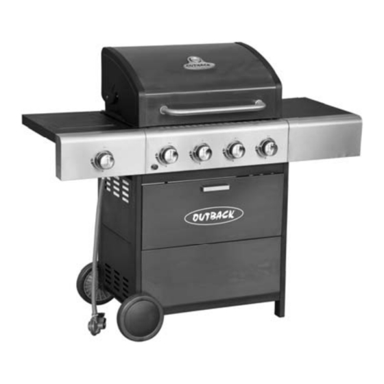
Assembly and Operating Instructions for Outback®
Meteor Select 4 Burner Gas BBQ
Drawings are not to scale.
Specifications subject to change
without prior notice.
•
For outdoor use only. Not for commercial use.
•
Read instructions before using the appliance. Failure to follow instructions could
result in death, serious bodily injury, and/or property loss.
•
Warning: accessible parts may be very hot. Keep young children and pets away.
•
Do not move the appliance during use.
•
Turn off the gas supply at the gas bottle after use.
•
Any modification of the appliance, misuse, or failure to follow the instructions may
be dangerous and will invalidate your warranty. This does not affect your statutory
WARNING
rights.
•
Retain these instructions for future reference.
•
Leak test annually, and whenever the gas bottle is removed or replaced. Check that
the hose connections are tight and leak test each time you reconnect the gas bottle.
•
For Flare-up control please refer to the 'OPERATION' section of this manual.
FOR YOUR SAFETY
If you smell gas:
1.
Shut off gas to the appliance.
2.
Extinguish any open flame.
3.
Open barbecue lid or hood.
4.
If odour continues, discontinue use and
contact your local dealer.
MT-H4430-3
FOR YOUR SAFETY
1.
Do not store or use petrol or other flammable
vapours or liquids in the vicinity of this or any
other appliance.
2.
A gas bottle not connected for use must not be
stored in the vicinity of this or any other
appliance.
0359
Advertisement

Related Manuals for Outback Meteor Select MT-H4430-3


Summary of Contents for Outback Meteor Select MT-H4430-3
- Page 1 Assembly and Operating Instructions for Outback® Meteor Select 4 Burner Gas BBQ Drawings are not to scale. MT-H4430-3 Specifications subject to change 0359 without prior notice. • For outdoor use only. Not for commercial use. • Read instructions before using the appliance. Failure to follow instructions could result in death, serious bodily injury, and/or property loss.
-
Page 2: Table Of Contents
Parts List Quantity varies according to model purchased. Specifications subject to change without prior notice. For more details on hardware, please see the corresponding ‘Hardware Reference Diagram’. Outback® Meteor Select 4 CODE PART Burner Gas BBQ Hood (Pre-Assembled to Body) -
Page 3: Parts Diagram
Parts Diagram Quantity varies according to model purchased. Specifications subject to change without prior notice. For more details on hardware, please see the corresponding ‘Hardware Reference Diagram’. - Page 4 Hardware Reference Diagram Specifications subject to change without prior notice.
- Page 5 Assembly IMPORTANT! • TOOLS NEEDED FOR ASSEMBLY: Medium size flat blade or Phillips/Crosspoint screwdriver, adjustable spanner or metric spanner set. • Remove any internal component or packaging from the barbecue body. • Whilst every care is taken in the manufacture of this product, care must be taken during assembly in case sharp edges are present.
- Page 6 Attach the left / right cabinet panel assembly to the Bottom Panel (C18) using M6x40 Bolts (D5x8pcs) and M6 Nuts (D6x8pcs) as shown. Unscrew the Locknuts (D7) from both ends of the Axle (C21). Slide the axle through the corresponding holes in the left legs. Slide the Wheels (C19) over each end of the axle.
- Page 7 Front Side Hole for assembling drip tray bracket Hole for assembling Ignition box Rear Side Attach Drip Tray Left Bracket (B10) to the right legs using ST4.0x10 Screws (D1x2pcs) as shown. Repeat above process for Drip Tray Right Bracket (B11). NOTE: Please Ignore Holes at Base of Front Panel(C16) No Screws are Required.
- Page 8 Fix the Electronic Ignition Assembly (C22) and Heat Shield (C23) to the front left leg by inserting two ST4.0x10 Screws (D1x2pcs) through the electronic ignition assembly and heat shield and screwing into the front left leg. Remove the retaining bolts from Storage Box Handle (C14), and then attach it onto Storage Box (C15) using the retaining bolts.
- Page 9 Install the storage box assembly between left / right front legs using M4 Step Bolts (D3x4pcs). Attach the Upper Body Support (C13) to the front legs using M6x15 Bolts (D4x4pcs).
- Page 10 Carefully place the Barbecue Body (B1) onto the cabinet structure and fix using M6x40 Bolts (D5x8pcs) as shown. WARNING: DO NOT RELEASE THE BARBECUE BODY WHILE THE BARBECUE HAS NOT BEEN PROPERLY SEATED. THIS MAY RESULT IN INJURY OR DAMAGE TO YOUR BARBECUE. CAUTION! Care must be taken to ensure the hood or lid does not fall open unexpectedly or becomes damaged when it is set on the ground.
- Page 11 Attach the side burner shelf assembly to the barbecue body using ST4.0x10 Screw (D1x2pcs) M6x15 Bolts (D4x4pcs) as shown. Attach the side burner valve and Knob Bezel (C4) onto side burner shelf using M4x10 Bolts (D2x2pcs) as shown. Press the Side Burner Knob (C5) onto side burner valve stem.
- Page 12 Feed the venturi tube of the Side Burner (C6) through the hole in bottom of the side burner shelf, and fix side it onto side burner shelf using a M4x10 Bolt (D2) as shown. Make sure that the end of venturi tube is set over the gas outlet of side burner valve.
- Page 13 Attach the side shelf assembly to the barbecue body using ST4.0x10 Screw (D1x2pcs) and M6x15 Bolts (D4x4pcs) as shown. B12 B13 Insert the Drip Tray (B12) by sliding it underneath the barbecue body. Place the Drip Pan (B13) in position as shown.
- Page 14 Large Leads Standard Leads Connect the wires to the electronic ignition assembly as shown in the diagram in the next step. Insert the electronic ignition battery (not supplied) into the battery compartment, ensuring the battery is correctly installed according to the (+) (-) markings. Electronic Ignition Assembly Diagram Black Black...
- Page 15 Remove the plastic wrap from the Lava Rock (B6) and then distribute the Lava Rock evenly in the Basket (B7). Lay the lava rock carefully into the body ensuring it lies level within the body. Lay the cooking grill (B8) and griddle (B9) into place. NOTE: Ensure that the lava rock lies directly underneath the grills.
-
Page 16: Warming Rack
Attach the Warming Rack (A3) to barbecue body as shown. ASSEMBLY IS NOW COMPLETE. PROCEED TO THE NEXT PAGE FOR INSTRUCTIONS ON OPERATION AND MAINTENANCE ALL JOINTS AND CONNECTIONS MUST NOW BE LEAK TESTED BEFORE USING THE BARBECUE. Leak test annually, and whenever the gas bottle is removed or replaced. Leak Testing Always perform a leak test in a well-ventilated area. -
Page 17: Burner
Important Information Before you use your barbecue, perform a leak test. This is the only safe and sure way Please read these instructions carefully to detect any gas leaking from joints and before assembly and use of your barbecue. connections of the barbecue after assembly. Leak test annually, and whenever the gas Retain these... -
Page 18: Control Panel
WARRANTY. Please consult your local gas Full coverage will cause excessive build-up dealer for the most suitable gas bottles and of heat and damage the barbecue. This is regulators. not covered by warranty. Preparation Before Cooking Installation To prevent foods from sticking to the cooking surface, please use a long handled brush to Selecting a Location apply a light coat of cooking or vegetable oil... -
Page 19: Lava Rock
lighting hole on the right side of the For best results, place the food you wish to barbecue body and place near rightmost bake or roast on a metal baking tray and set it burner porthole. on one side of the cooking grill. •... -
Page 20: Drip Tray
If a fat fire occurs, please see the instructions cleaning. Do not leave the barbecue exposed to given below. outside weather conditions or stored in damp, moist areas. Fat Fires Empty and clean the drip tray and drip pan (and Never handle hot parts with unprotected foil liner, if applicable) of food debris after each hands. - Page 21 cooking will keep the burners clean. Barbecue Hood or Lid & Trolley Use a non-abrasive cloth or pad and clean with The burners should be removed and cleaned hot, soapy water. Do not use scouring pads or annually, or whenever heavy build-up is found, powders as they can permanently damage the to ensure that there are no signs of blockage finish.
-
Page 22: Technical Specifications
0.84mm Burner 359BR665 or 37 mbar Propane Gas Consumption: Outback® Meteor Select 4 Burner Gas BBQ: 943g/hr Side Burner: 214g/hr Countries of Use: BE, CH, CY, CZ, ES, FR, GB, GR, IE, IT, LT, LU, LV, PT, 3+ (28-30/37) SK, SI... -
Page 23: Ignition Button
Troubleshooting Problem Possible Cause Solution Burner will not light using LP gas bottle is empty Replace with full bottle the ignition system Faulty regulator Have regulator checked or replaced Obstructions in burner Clean burner Obstructions in gas jets or gas hose Clean jets and gas hose Electrode or ignition button wire is loose Reconnect wire... - Page 24 (10) years from the date of purchase. Stainless steel and cast iron burners are warranted for a period of two (2) years from the date of purchase. OUTBACK will, within this period, supply replacements for defective parts free of charge provided that: ♦...
Need help?
Do you have a question about the Meteor Select MT-H4430-3 and is the answer not in the manual?
Questions and answers