Outback Jupiter 4 Assembly And Operating Instructions Manual
Burner gas bbq
Hide thumbs
Also See for Jupiter 4:
- Assembly and operating instructions manual (23 pages) ,
- Assembly and operating instructions manual (24 pages) ,
- Assembly and operating instructions manual (24 pages)
Table of Contents
Advertisement
Quick Links
Assembly and Operating Instructions for Outback®
Drawings are not to scale.
Specifications subject to change
without prior notice.
•
For outdoor use only. Not for commercial use.
•
Read instructions before using the appliance. Failure to follow instructions could
result in death, serious bodily injury, and/or property loss.
•
Warning: accessible parts may be very hot. Keep young children and pets away.
•
Do not move the appliance during use.
•
Turn off the gas supply at the gas bottle after use.
•
Any modification of the appliance, misuse, or failure to follow the instructions may
be dangerous and will invalidate your warranty. This does not affect your statutory
WARNING
rights.
•
Retain these instructions for future reference.
•
Leak test annually, and whenever the gas bottle is removed or replaced. Check that
the hose connections are tight and leak test each time you reconnect the gas bottle.
•
For Flare-up control please refer to the 'OPERATION' section of this manual.
FOR YOUR SAFETY
If you smell gas:
1.
Shut off gas to the appliance.
2.
Extinguish any open flame.
3.
Open barbecue lid or hood.
4.
If odour continues, discontinue use and
contact your local dealer.
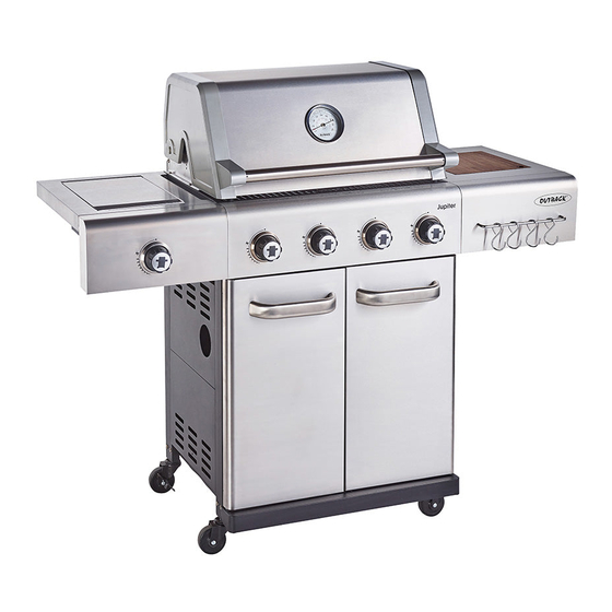
Jupiter 4 Burner Gas BBQ
MS4491
1.
2.
FOR YOUR SAFETY
Do not store or use petrol or other flammable
vapours or liquids in the vicinity of this or any
other appliance.
A gas bottle not connected for use must not be
stored in the vicinity of this or any other
appliance.
0359
Advertisement
Table of Contents

Related Manuals for Outback Jupiter 4


Summary of Contents for Outback Jupiter 4
- Page 1 Assembly and Operating Instructions for Outback® Jupiter 4 Burner Gas BBQ MS4491 Drawings are not to scale. Specifications subject to change 0359 without prior notice. • For outdoor use only. Not for commercial use. • Read instructions before using the appliance. Failure to follow instructions could result in death, serious bodily injury, and/or property loss.
-
Page 2: Parts List
Quantity varies according to model purchased. Specifications subject to change without prior notice. For more details on hardware, please see the corresponding ‘Hardware Reference Diagram’. Outback® CODE PART Jupiter 4 Burner Gas BBQ Hood (Pre-Assembled to Body) Hood Handle HOOD Heat Indicator... -
Page 3: Parts Diagram
Parts Diagram Quantity varies according to model purchased. Specifications subject to change without prior notice. For more details on hardware, please see the corresponding ‘Hardware Reference Diagram’. - Page 4 Hardware Reference Diagram Specifications subject to change without prior notice.
- Page 5 Assembly IMPORTANT! TOOLS NEEDED FOR ASSEMBLY: Medium size flat blade or Phillips/Crosspoint screwdriver, • adjustable spanner or metric spanner set. Remove any internal component or packaging from the barbecue body. • Whilst every care is taken in the manufacture of this product, care must be taken during assembly in •...
- Page 6 Attach the Rear Panel (C16) to the cabinet assembly using ST4.0x10 Screws (D2x7pcs) as shown. Bottom View Attach the Storage Unit (C19) onto the Bottom Panel (C17) using M6x15 Bolts (D3x4pcs) as shown.
- Page 7 Side view of drip tray bracket Front Rear Attach the Drip Tray Left Bracket (B11) to the left cabinet panel using ST4.0x10 Screws (D2x2pcs) as shown. Repeat above process for Drip Tray Right Bracket (B12). Please note: Drip tray brackets will attach at a slight angle. Attach the Upper Support (C12) to the left/right cabinet panel using M6x15 Bolts (D3x4pcs).
- Page 8 Carefully turn the cabinet upside-down. Attach the Lockable Casters (C21x2pcs) into the rear side holes of the left/right cabinet panel and the Casters (C20x2pcs) into the front side holes of the left/right cabinet panel, as shown. Remove the retaining bolts from one Door Handle (C13), and then attach the door handle onto the Left Door (C14) using the retaining bolts as shown.
- Page 9 Fit the doors to the cabinet by depressing the spring pins and placing into the cabinet. Carefully place the Barbecue Body (B1) onto the cabinet assembly and fix using M6x15 Bolts (D3x4pcs) as shown.
- Page 10 Connect the Hose and Regulator Assembly (B5) to the barbecue. Ensure the mating faces of the connection are clean and not damaged. Do not use any sealing tape, paste, or liquid on the connection. The nut must be tightened with the use of a spanner. Do not use force which may damage the assembly.
- Page 11 Attach the side shelf assembly to the barbecue body using ST4.0x10 Screw (D2x2pcs) and M6x15 Bolts (D3x4pcs) as shown. Attach Side Burner Shelf Panel (C2) onto Side Burner Shelf (C1) using M6x15 Bolts (D3x2pcs) and M6 Nut (D4x2pcs) as shown.
- Page 12 Attach the side burner shelf assembly to the barbecue body using ST4.0x10 Screw (D2x2pcs) and M6x15 Bolts (D5x4pcs) as shown. Attach the side burner valve and Knob Bezel (C6) onto side burner shelf using M4x10 Bolts (D5x2pcs) as shown. Press the Side Burner Knob (C7) onto side burner valve stem. Ensure there are no rings in side burner hose and hose does not contact any parts as shown in C.
- Page 13 Unscrew the pre-assembled nut of the Ignition Button (B15). Insert the Ignition Button (B15) into the hole at the side burner shelf panel and secure with the pre-assembled nut. Main burner wire Side burner wire Connect the electrode wire to the Ignition Button (B15). WARNING: BEFORE OPERATION, ENSURE BOTH MAIN BURNER AND SIDE BURNER WIRES ARE CONNECTED TO PUSH BUTTON IGNITOR.
- Page 14 3-5mm Feed the venturi tube of the Side Burner (C8) through the hole in bottom of the side burner shelf, and fix it onto side burner shelf using a M4x10 Bolt (D5) as shown. Make sure that the end of venturi tube is set over the gas outlet of side burner valve. Remove the plastic wrap from the Large Lava Rock in Basket (B6) and Small Lava Rock in Basket (B7), Lay the lava rock carefully into the body ensuring it lies level within the body.
- Page 15 Step 1 Step 2 Step 3 Step 4 Place the Side Burner Grid (C6) onto the side burner shelf. Attach the Warming Rack (A4) to the Hood (A1) and Barbecue Body (B1) as shown. Make sure that the swing legs fix to the body of the barbecue and the shorter fixed legs go through the holes in the hood.
- Page 16 Attach the Tool Hook (C5) onto the Side Shelf (C3) using M6x15 Bolts (D3x2pcs) and M6 Nuts (D4x2pcs) as shown. ASSEMBLY IS NOW COMPLETE.
-
Page 17: Leak Testing
1. Maximum diameter or breadth is 320mm. 2. Maximum height (regulator included) is 700mm. ASSEMBLY IS NOW COMPLETE ALL JOINTS AND CONNECTIONS MUST NOW BE LEAK TESTED BEFORE USING THE BARBECUE Leak test annually, and whenever the gas bottle is removed or replaced Leak Testing Always perform a leak test in a well-ventilated area. -
Page 18: Gas, Regulator And Hose
Important Information Before you use your barbecue, perform a leak test. This is the only safe and sure way Please read these instructions carefully to detect any gas leaking from joints and before assembly and use of your barbecue. connections of the barbecue after assembly. Leak test annually, and whenever the gas Retain these... -
Page 19: Installation
INCORRECT OR FAULTY REGULATOR IS understand IMPORTANT DANGEROUS AND WILL INVALIDATE ANY INFORMATION section of this manual. WARRANTY. Please consult your local gas Your barbecue is not designed to be used dealer for the most suitable gas bottles and with more than 50% of the cooking area as a regulators. - Page 20 Manual Ignition Instructions keeping food warm. • Open the barbecue and side burner hood or lid before lighting. Never light your Roasting Hood Cooking barbecue or side burner with the hood or lid Barbecues equipped with a roasting hood give closed.
-
Page 21: Care And Maintenance
meat or meat products as these tend to have a Wait until the barbecue is sufficiently cool high fat and water content. Also, the burners before closing its hood. should always be placed on the low setting during cooking. Care and Maintenance When flare-ups do occur, they can usually be extinguished by applying baking soda or salt Regularly clean your barbecue between uses... -
Page 22: Technical Specifications
Regularly remove excess grease or fat from the Gas Consumption: barbecue body using a cloth wrung out in hot Outback® Jupiter 4 Burner Gas BBQ: 943g/hr soapy water and dry thoroughly. Excess fat and Side Burner: 214g/hr food debris can be removed from inside the Countries of Use: body using a soft plastic or wooden scraper. -
Page 23: Troubleshooting
Troubleshooting Problem Possible Cause Solution Burner will not light using LP gas bottle is empty Replace with full bottle the ignition system Faulty regulator Have regulator checked or replaced Obstructions in burner Clean burner Obstructions in gas jets or gas hose Clean jets and gas hose Electrode or ignition button wire is loose Reconnect wire... - Page 24 OUTBACK® WARRANTY OUTBACK® barbecues are warranted to the original purchaser against defects in materials and workmanship. OUTBACK® will supply replacements for defective parts free of charge provided that: The product has not been used for trade, professional or hire purposes.
Need help?
Do you have a question about the Jupiter 4 and is the answer not in the manual?
Questions and answers