Table of Contents
Advertisement
Quick Links
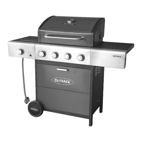
Assembly and Operating Instructions for Outback®
Drawings are not to scale.
Specifications subject to change
without prior notice.
WARNING
Retain these instructions for future reference.
Leak test annually, and whenever the gas bottle is removed or replaced. Check that
For Flare-up control please refer to the 'OPERATION' section of this manual.
FOR YOUR SAFETY
If you smell gas:
1.
Shut off gas to the appliance.
2.
Extinguish any open flame.
3.
Open barbecue lid or hood.
4.
If odour continues, discontinue use and
contact your local dealer.
Meteor 4 Burner Gas BBQ
For outdoor use only. Not for commercial use.
Read instructions before using the appliance. Failure to follow instructions could
result in death, serious bodily injury, and/or property loss.
Warning: accessible parts may be very hot. Keep young children and pets away.
Do not move the appliance during use.
Turn off the gas supply at the gas bottle after use.
Any modification of the appliance, misuse, or failure to follow the instructions may
be dangerous and will invalidate your warranty. This does not affect your statutory
rights.
the hose connections are tight and leak test each time you reconnect the gas bottle.
MS4431CD
FOR YOUR SAFETY
1.
Do not store or use petrol or other flammable
vapours or liquids in the vicinity of this or any
other appliance.
2.
A gas bottle not connected for use must not be
stored in the vicinity of this or any other
appliance.
0359
Advertisement
Table of Contents

Related Manuals for Outback Meteor 4


Summary of Contents for Outback Meteor 4
- Page 1 Assembly and Operating Instructions for Outback® Meteor 4 Burner Gas BBQ MS4431CD Drawings are not to scale. Specifications subject to change 0359 without prior notice. For outdoor use only. Not for commercial use. Read instructions before using the appliance. Failure to follow instructions could result in death, serious bodily injury, and/or property loss.
-
Page 2: Parts List
Parts List Quantity varies according to model purchased. Specifications subject to change without prior notice. For more details on hardware, please see the corresponding ‘Hardware Reference Diagram’. Outback® Meteor 4 Burner CODE PART Gas BBQ Hood (Pre-Assembled to Body) ... -
Page 3: Parts Diagram
Parts Diagram Quantity varies according to model purchased. Specifications subject to change without prior notice. For more details on hardware, please see the corresponding ‘Hardware Reference Diagram’. - Page 4 Hardware Reference Diagram Specifications subject to change without prior notice.
- Page 5 Assembly IMPORTANT! TOOLS NEEDED FOR ASSEMBLY: Medium size flat blade or Phillips/Crosspoint screwdriver, adjustable spanner or metric spanner set. Remove any internal component or packaging from the barbecue body. Whilst every care is taken in the manufacture of this product, care must be taken during assembly in ...
- Page 6 Attach the left / right cabinet panel assembly to the Bottom Panel (C19) using M6x40 Bolts (D5x8pcs) and M6 Nuts (D6x8pcs) as shown. Unscrew the Locknuts (D7) from both ends of the Axle (C22). Slide the axle through the corresponding holes in the left legs. Slide the Wheels (C20) over each end of the axle.
- Page 7 Attach Drip Tray Left Bracket (B8) to the left legs using ST4.0x10 Screws (D1x2pcs) as shown. Repeat above process for Drip Tray Right Bracket (B9). NOTE: Please Ignore Holes at Base of Front Panel(C17) No Screws are Required. Install Front Panel (C17) between left / right front legs using ST4.0x10 Screws (D1x4pcs).
- Page 8 Remove the retaining bolts from Storage Box Handle (C15), and then attach it onto Storage Box (C16) using the retaining bolts. Install the storage box assembly between left / right front legs using M4x10 Step Bolts (D3x4pcs).
- Page 9 Attach the Upper Support (C14) to the front legs using M6x15 Bolts (D4x4pcs). Remove the retaining bolts from legs, and then attach Body Support A (C23) onto the left rear leg and right front leg and attach Body Support B (C24) onto the right rear leg and left front leg using the retaining bolts.
- Page 10 Carefully place the Barbecue Body (B1) onto the cabinet structure and fix using M6x40 Bolts (D5x8pcs) as shown. Attach Side Burner Shelf Panel (C2) onto Side Burner Shelf (C1) using M6x15 Bolts (D4x2pcs) and M6 Nuts (D6x2pcs).
- Page 11 step1 step2 step3 step4 Attach the side burner shelf assembly to the barbecue body using ST4.0x10 Screw (D1x2pcs) M6x15 Bolts (D4x4pcs) as shown. Attach the side burner valve and Knob Bezel (C4) onto side burner shelf using M4x10 Bolts (D2x2pcs) as shown.
- Page 12 Unscrew the pre-assembled nut of the Ignition Button (C6). Insert the Ignition Button (C6) into the hole at the side burner shelf panel and secure with the pre-assembled nut. Feed the venturi tube of the Side Burner (C7) through the hole in bottom of the side burner shelf, and fix side it onto side burner shelf using a M4x10 Bolt (D2) as shown.
- Page 13 Main burner wire Side burner wire Connect the electrode wire to the Ignition Button (C6). WARNING: BEFORE OPERATION, ENSURE BOTH MAIN BURNER AND SIDE BURNER WIRES ARE CONNECTED TO PUSH BUTTON IGNITOR. IF THE CIRCUIT IS NOT COMPLETED, THE IGNITOR WILL NOT SPARK! Attach Side Shelf Panel (C9) onto Side Shelf (C8) using M6x15 Bolts (D4x2pcs) and M6 Nuts (D6x2pcs).
- Page 14 step1 step2 step4 step3 Attach the side shelf assembly to the barbecue body using ST4.0x10 Screw (D1x2pcs) and M6x15 Bolts (D4x4pcs) as shown. Insert the Drip Tray (B10) by sliding it underneath the barbecue body as shown.
- Page 15 Lay the Flame Tamers (B6) carefully into the body ensuring it lies level within the body. Lay the Cooking Grills (B7) into place. Place the Side Burner Grid (C3) onto the side burner shelf. NOTE: Make sure the base of cooking utensil to put on the side burner is larger than 150mm and smaller than 220mm.
- Page 16 Step 1 Step 2 Step 3 Step 4 Attach the Warming Rack (A3) to the hood and barbecue body as shown. Make sure that the swing legs fix to the body of the barbecue and the shorter fixed legs go through the holes in the hood.
-
Page 17: Leak Testing
1. Maximum diameter or breadth is 320mm. 2. Maximum height (regulator included) is 700mm. PROCEED TO THE NEXT PAGE FOR INSTRUCTIONS ON OPERATION AND MAINTENANCE ALL JOINTS AND CONNECTIONS MUST NOW BE LEAK TESTED BEFORE USING THE BARBECUE. Leak test annually, and whenever the gas bottle is removed or replaced. Leak Testing Always perform a leak test in a well-ventilated area. -
Page 18: Gas, Regulator And Hose
Important Information leak test. This is the only safe and sure way to detect any gas leaking from joints and connections of the barbecue after assembly. Please read these instructions carefully before assembly and use of your barbecue. Leak test annually, and whenever the gas bottle is removed or replaced. -
Page 19: Installation
Installation surface, please use a long handled brush to apply a light coat of cooking or vegetable oil before each barbecuing session. (Note: Selecting a Location When cooking for the first time, paint colours This barbecue is for outdoor use only and may change slightly as a result. - Page 20 burner porthole. gauge to monitor the heat of the barbecue. Push and turn the rightmost control knob If the internal heat becomes too high, turn the anti-clockwise to the high position, taking burners down to the low position. It is not care to protect yourself from the flames.
-
Page 21: Care And Maintenance
may result in a fat fire, which may cause injury local stockist. and could seriously damage the barbecue. Even when your barbecue is covered for its protection, it must be inspected on a regular In the event of a fat fire: basis as damp or condensation can form which ... -
Page 22: Technical Specifications
Injector Burners A stainless steel cleaner may be used on Approval Input Size Consumption stainless steel parts if required. Outback® Meteor 4 0359 12.96 Butane: 943g/hr Barbecue Hood or Lid & Trolley 0.89mm Burner Gas 359BR665 Propane: 926g/hr Use a non-abrasive cloth or pad and clean with hot, soapy water. -
Page 23: Troubleshooting
Troubleshooting Problem Possible Cause Solution Burner will not light using LP gas bottle is empty Replace with full bottle the ignition system Faulty regulator Have regulator checked or replaced Obstructions in burner Clean burner Obstructions in gas jets or gas hose Clean jets and gas hose Electrode or ignition button wire is loose Reconnect wire... - Page 24 Other parts are warranted for a period of one (1) year from the date of purchase. OUTBACK® will, within above periods, supply replacements for defective parts free of charge provided that: The product has not been used for trade, professional or hire purposes.
Need help?
Do you have a question about the Meteor 4 and is the answer not in the manual?
Questions and answers
Order parts - burners corroded yellow flames